Промышленная зона Вэньян Юэцин Вэньчжоу 325000
Рабочие часы
Понедельник - пятница: 7AM - 7PM
Выходные: 10AM - 5PM
Промышленная зона Вэньян Юэцин Вэньчжоу 325000
Рабочие часы
Понедельник - пятница: 7AM - 7PM
Выходные: 10AM - 5PM

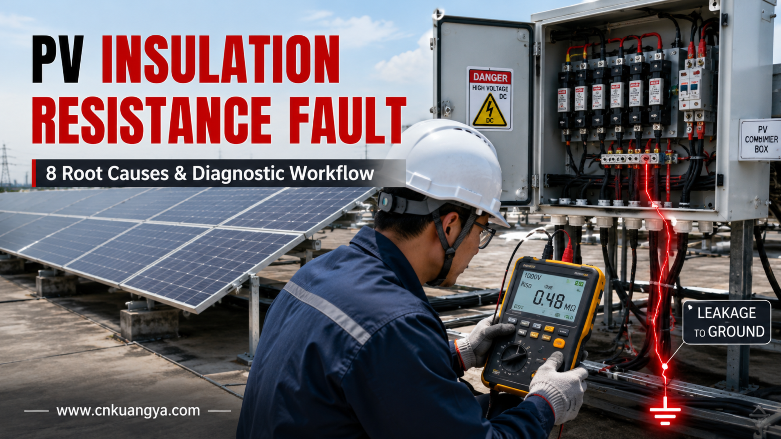
A Неисправность сопротивления изоляции фотоэлектрической системы является одной из самых сложных проблем при эксплуатации и техническом обслуживании солнечных электростанций.
Инвертор может не запускаться по утрам. Предупреждение может исчезнуть через несколько часов сухой погоды и появиться снова после дождя. Одна цепочка может выглядеть электрически исправной при измерении напряжения холостого хода, однако вся фотоэлектрическая система по-прежнему сообщает о низком сопротивлении изоляции.
Эти неисправности сложны тем, что проблема не всегда заключается в прямом коротком замыкании.
Солнечная батарея может продолжать вырабатывать напряжение, которое кажется нормальным, в то время как влага, поврежденная изоляция, загрязненные разъемы, изношенные компоненты модулей или неисправное устройство постоянного тока создают нежелательный токопроводящий путь между цепью постоянного тока под напряжением и землей.
Результатом может быть:
В данном руководстве объясняется, как возникают неисправности изоляции в фотоэлектрических системах, почему они часто носят прерывистый характер и как технические специалисты могут использовать структурированный процесс диагностики вместо хаотичной замены компонентов.
Проектирование фотоэлектрических массивов должно учитывать требования к прокладке кабелей постоянного тока, электрической защите, заземлению, контролю изоляции и обнаружению замыканий на землю. Эти принципы безопасности рассматриваются в IEC 62548-1 для проектирования фотоэлектрических массивов. Текущая редакция стандарта IEC 62548-1 охватывает вопросы прокладки кабелей постоянного тока, электрической защиты, коммутации и заземления фотоэлектрических массивов, в то время как IEC 62446-1 посвящен документации, приемо-сдаточным испытаниям и инспекциям, а IEC 62446-2 — техническому обслуживанию и поиску неисправностей в сетевых фотоэлектрических системах.
Наиболее распространенные причины включают:
Самое важное правило при поиске неисправностей:
Не рассматривайте неисправность изоляции фотоэлектрической системы как проблему инвертора, пока массив постоянного тока не будет систематически изолирован и протестирован.
Инвертор может просто обнаруживать проблему, расположенную где-то выше по цепи в фотоэлектрическом поле.
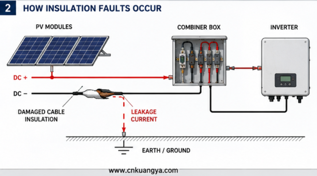
В исправной фотоэлектрической системе положительные и отрицательные проводники постоянного тока должны оставаться надлежащим образом изолированными от доступных токопроводящих частей и земли в соответствии с проектом системы.
Проблема с изоляцией возникает, когда между цепью постоянного тока под напряжением и другим токопроводящим путем или заземлением образуется непреднамеренный токопроводящий путь.
Этот путь может быть создан следующими факторами:
Неисправность не обязательно начинается как полное металлическое короткое замыкание.
Она может начинаться как относительно слабый путь утечки тока.
Именно поэтому фотоэлектрическая система иногда может:
Такое прерывистое поведение — одна из причин, по которой неисправности изоляции могут отнимать много времени на техническое обслуживание.
Современное оборудование для преобразования электроэнергии может контролировать электрическую связь между цепью постоянного тока фотоэлектрической системы и землей до или во время работы.
Если обнаруженное состояние изоляции выходит за пределы допустимого диапазона, установленного производителем инвертора, инвертор может:
Точное название аварийного сигнала зависит от производителя.
Примеры описаний, часто встречающихся на практике, включают:
Важно отметить, что аварийный сигнал указывает на состояние, а не обязательно неисправный компонент.
Таким образом, замена инвертора без проверки фотоэлектрического массива может не решить проблему.
Стандарты установки фотоэлектрических систем разграничивают проектирование массива, монтаж оборудования, а также процессы тестирования и технического обслуживания. Следовательно, надлежащая диагностика должна охватывать всю систему постоянного тока, а не только оборудование для преобразования энергии.
Поэтому сигнал об ошибке изоляции следует рассматривать как часть более широкой архитектуры защиты цепей постоянного тока, а не как изолированную проблему инвертора. Для более детального ознакомления с рисками перенапряжения, сверхтоков, дуговых замыканий, заземления и нарушения изоляции вокруг инвертора см. наше руководство по Защите солнечных инверторов.
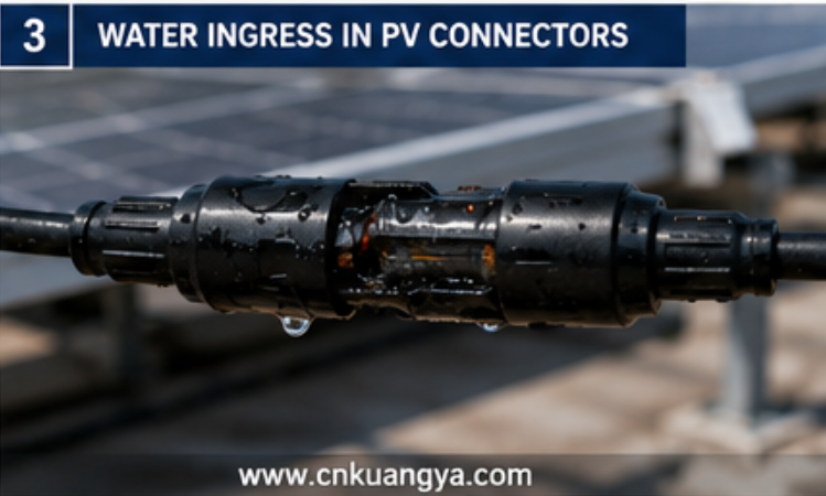
Попадание влаги — это одно из первых условий, которое должны проверить технические специалисты, если сигнал об ошибке изоляции тесно связан с погодными условиями.
Разъем может выглядеть механически соединенным, при этом пропуская влагу к токопроводящим поверхностям.
Возможные причины включают:
Неисправность может быть трудновоспроизводимой.
В сухую погоду путь утечки может стать достаточно слабым для запуска инвертора.
После дождя или образования конденсата проводимость увеличивается, и сигнал тревоги возобновляется.
Система:
Этот характер повреждений должен немедленно привлечь внимание к компонентам, чувствительным к воздействию влаги.
Однако техническим специалистам не следует полагать, что первый обнаруженный влажный разъем является единственной проблемой.
Крупные массивы могут содержать несколько точек деградации.
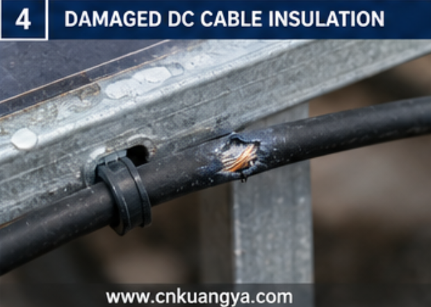
Фотоэлектрические кабели подвергаются длительному воздействию окружающей среды и механическим нагрузкам.
Возможные механизмы повреждения включают:
A cable does not need to be completely severed to create an insulation problem.
A small damaged area may expose insulation to:
The resulting leakage path can be intermittent.
Technicians often inspect only visible cable sections.
But cable damage frequently occurs at:
A good inspection therefore follows the actual cable route rather than only the easy-to-see portions.
Not every insulation fault originates in the field wiring.
The PV module itself can become part of the leakage path.
Potential areas include:
Environmental exposure can gradually affect electrical insulation.
The diagnostic challenge is that module output voltage may still appear normal.
A technician may measure acceptable open-circuit voltage and conclude that the module is healthy.
However:
Normal voltage does not prove that insulation to earth is healthy.
These are different electrical conditions.
Module safety requirements are intended to address risks including breakdown of internal or external components that could contribute to electric shock or fire hazards.
Connector problems are frequently discussed only as overheating or arc-fault risks.
However, poor connector installation can also contribute to insulation problems.
Possible issues include:
A connector problem may evolve over time.
The sequence can be:
Mechanical weakness → moisture entry → corrosion or contamination → reduced insulation performance
In another case:
Poor electrical contact → heating → material degradation → carbonized conductive path
This shows why insulation resistance, thermal problems and arc-fault risks should not always be treated as completely separate failure categories.
One defect can develop through several stages.
A surge protective device is installed to manage transient overvoltage.
However, an SPD is also connected electrically between the protected conductors and the relevant protection path.
After repeated electrical stress or internal deterioration, a damaged device may become part of a leakage problem.
Therefore, when troubleshooting an unexplained insulation fault inside a:
the SPD should be included in the diagnostic process.
Do not simply remove an SPD permanently because the insulation alarm disappears.
That only identifies a possible fault source.
The correct action is to:
A failed protection device should not be solved by leaving the system unprotected.
IEC 62548-1 includes the design of DC array wiring and electrical protection devices within PV arrays.
The DC isolator is another component that should not be ignored.
Inside a DC switching device, insulation performance can be affected by:
An isolator may still appear to switch mechanically while its internal electrical condition has deteriorated.Moisture ingress, contaminated insulating surfaces, heat damage, and deteriorated internal contacts can also create broader reliability problems. Our detailed guide to DC Isolator Switch Failure explains how these defects develop and how they should be inspected.
Visible warning signs may include:
However, not every insulation defect is externally visible.
A systematic diagnostic process may require isolating sections of the circuit to determine whether the fault remains upstream or downstream of a particular device.
Many PV insulation faults are created during installation but appear months or years later.Incorrect cable routing, poor terminal preparation, reversed polarity, unsuitable protection devices, and installation errors can also create hidden DC-side defects. See 10 Common DC Protection Wiring Mistakes for a broader review of installation practices that can reduce long-term system reliability.
Consider a cable that is:
On the installation day, the insulation may remain intact.
Later, repeated:
can turn a minor installation defect into an electrical fault.
Projects in different environments may experience different dominant risks.
Possible concerns include:
Possible concerns include:
Possible concerns include:
The same alarm code can therefore have very different physical causes depending on the project environment.
Sometimes technicians search for one dramatically failed component.
But a large array may have no single obvious fault.
Instead, many small leakage paths can combine.
A large installation contains:
Each individual component may contribute only a small leakage path.
Together, however, the total insulation condition seen by the monitoring system can become problematic.
This is especially important when troubleshooting:
The diagnostic method must therefore be capable of dividing the system into smaller sections.
Without sectional isolation, technicians may spend hours looking for one visibly damaged component that does not exist.
This is one of the most useful diagnostic clues.
A solar plant may report:
Low insulation resistance at 6:30 a.m.
Then:
Normal operation at 10:00 a.m.
Почему?
One possible explanation is environmental moisture.
Overnight:
After sunrise:
The system appears to “repair itself.”
It has not.
The underlying defect may still exist.
This is why maintenance teams should record:
Fault timing can provide important information before the first electrical test is performed.
These terms are often used incorrectly.
An unwanted conductive path reduces the electrical isolation between the live circuit and earth or other conductive parts.
It may be relatively weak or intermittent.
A live conductor develops an unintended connection toward ground or grounded conductive material.
The severity depends on the electrical system and fault path.
A low-impedance connection occurs between points that should remain at different electrical potentials.
This can produce much higher current.
Current crosses an unintended gap through an electrical arc.
An arc fault may be:
A system can also experience more than one fault mechanism simultaneously.
Например:
Damaged insulation → leakage → carbonization → arc formation
Therefore, accurate diagnosis is more useful than simply assigning one general label such as “electrical fault.”
Random component replacement is one of the least efficient ways to troubleshoot a large PV system.
A better method is progressive isolation.
Before resetting the system, record:
This information may later reveal a pattern.
PV arrays can remain energized when exposed to sufficient light.
Technicians should follow the required site procedures, equipment instructions and applicable electrical safety practices before disconnecting, testing or opening equipment.
IEC 62446-1 addresses commissioning tests and inspection, while IEC 62446-2 provides maintenance-related requirements and recommendations for grid-connected PV systems, including corrective maintenance and troubleshooting.
The key question is:
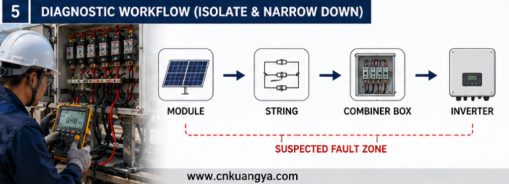
Is the fault in the inverter, main DC circuit, combiner box, string wiring or module section?
Large systems should be progressively divided into smaller electrical sections.
The objective is to determine:
Fault remains → problem is still inside the connected section
или
Fault disappears → investigate the isolated section
This is more efficient than testing every module immediately.
When multiple strings are available, compare the suspected string with healthy strings.
Useful comparisons may include:
The objective is to identify the abnormal branch.
Prioritize locations such as:
Visual inspection should support electrical testing rather than replace it.
Once a problematic string is identified, divide the string or circuit into smaller sections where the system design and safe procedures allow.
This transforms:
“The entire PV plant has an insulation fault.”
into:
“The problem is located within this specific section.”
That is the central principle of efficient fault localization.
After identifying the fault source:
Then verify that the system has returned to an acceptable condition before normal operation.
An intermittent fault creates a dangerous temptation.
The technician resets the inverter.
The system starts.
The service ticket is closed.
Then the alarm returns after the next rain.
Restarting may temporarily restore generation, but it does not answer:
Repeated resets can turn a diagnosable early-stage problem into a more expensive failure.
Avoid:
Connectors should not carry unnecessary cable weight or remain in positions where water and contamination can accumulate.
Combiner boxes and other outdoor enclosures require:
Heavy rain and extreme environmental conditions can reveal developing insulation weaknesses.
Do not wait until an inverter refuses to start.
Periodic inspection and testing can help identify deterioration before it becomes a prolonged production problem.
IEC 62446-2 specifically addresses preventive, corrective and performance-related maintenance of grid-connected PV systems, including maintenance for reliability, safety, fire prevention and troubleshooting.
Experienced troubleshooting teams do not look only at the alarm.
They look at the pattern.
| Fault Pattern | Possible Direction |
|---|---|
| Only after rain | Moisture or ingress |
| Mainly early morning | Condensation-sensitive leakage |
| One specific string | Local string or module fault |
| Entire array | Common DC equipment or distributed leakage |
| After maintenance | Installation or reconnection issue |
| After electrical storm | Inspect affected protective equipment and connected circuits |
| Gradually increasing frequency | Progressive deterioration |
This table is not a substitute for testing.
Its purpose is to help determine where investigation should begin.
It generally means that the electrical isolation between the live PV DC circuit and earth or other conductive parts is lower than the equipment or system expects.
The cause must be identified through inspection and testing.
Moisture may create or strengthen an unintended leakage path in:
The fact that the fault disappears after drying does not mean the system is permanently repaired.
Да.
Possible sources can include the module junction box, external leads or deterioration of the module insulation system.
Normal open-circuit voltage alone does not prove healthy insulation.
A damaged or degraded device connected to the DC protection circuit may need to be considered during diagnosis.
The device should be tested or replaced appropriately rather than permanently removed from the protection system.
Potentially.
Moisture, contamination, heat damage or internal electrical degradation may affect the condition of the device.
Temperature and moisture conditions may change.
Morning condensation or humidity can strengthen a leakage path that becomes less conductive as equipment dries and warms.
Not automatically.
The inverter may simply be detecting an upstream PV array problem.
The DC field should be systematically investigated before the inverter is assumed to be defective.
Нет.
They are different electrical fault mechanisms, although deterioration can sometimes allow one fault condition to develop into another.
A Неисправность сопротивления изоляции фотоэлектрической системы should not be treated as a mysterious inverter error.
It is an electrical condition that requires structured fault localization.
Наиболее распространенные причины включают:
The most effective diagnostic strategy is not random replacement.
А в том:
Record → Isolate → Divide → Compare → Inspect → Test → Repair → Verify
This method turns a plant-wide alarm into a manageable electrical problem.
As photovoltaic systems become larger and DC architectures become more complex, insulation integrity remains a fundamental part of safe and reliable PV operation. Current IEC frameworks separately address PV array design, electrical installation, testing, inspection and maintenance, reinforcing the need to treat insulation performance as a system-level engineering issue rather than simply an inverter alarm.

