Промышленная зона Вэньян Юэцин Вэньчжоу 325000
Рабочие часы
Понедельник - пятница: 7AM - 7PM
Выходные: 10AM - 5PM
Промышленная зона Вэньян Юэцин Вэньчжоу 325000
Рабочие часы
Понедельник - пятница: 7AM - 7PM
Выходные: 10AM - 5PM
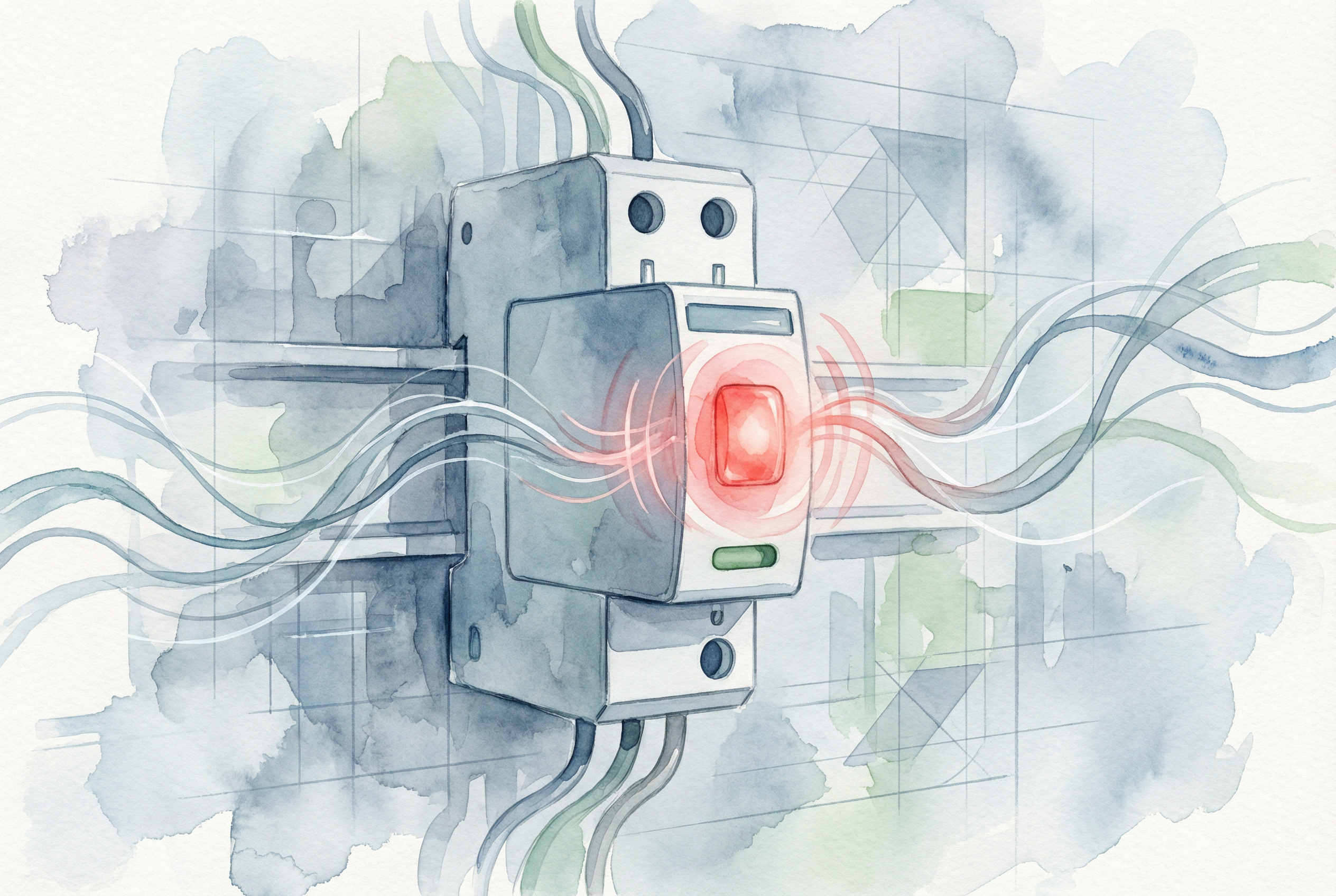
Это знакомый сценарий для любого добросовестного менеджера или инженера. Во время рутинного обхода объекта ваш взгляд пробегает по ряду панелей управления, и ваше внимание привлекает маленький, но настойчивый красный огонек. Она горит на устройстве защиты от перенапряжения (СПД), компонент, который тихо стоит на страже чувствительного оборудования стоимостью в тысячи и даже миллионы долларов. Зеленый свет означает, что все в порядке, но красный - это повод для немедленного беспокойства. Система в опасности? Происходит ли активный скачок напряжения? Не грозит ли катастрофический отказ?
Именно в этот момент неопределенности очень важно понимать, как устроена ваша электрическая инфраструктура. Хотя красный свет на СПД - это срочный сигнал, требующий принятия мер, зачастую он не является предвестником катастрофы, которой вы опасаетесь. В большинстве современных, отвечающих требованиям СПД красный свет - это своего рода история успеха. Это запрос на техническое обслуживание, а не сигнал пожарной тревоги.
Это исчерпывающее руководство поможет понять, что такое красный индикатор. Мы рассмотрим, что происходит внутри устройства с технической точки зрения, диагностируем основные причины, приводящие к окончанию срока службы, предоставим пошаговое руководство по устранению неисправностей для вашей команды и изложим основные передовые методы предотвращения преждевременных отказов в будущем. К концу семинара вы сможете воспринимать красный свет не как проблему, а как ее решение - знак того, что ваша система защиты от перенапряжений выполнила свою работу и готова к плановой замене.
Чтобы понять, что означает красный свет, сначала нужно заглянуть внутрь SPD. Рабочей лошадкой большинства СПД является металлооксидный варистор, или MOV. Представьте себе MOV как высокочувствительный затвор, управляемый напряжением. При нормальных условиях напряжения он остается в состоянии высокого сопротивления, позволяя бесперебойно подавать питание на ваше оборудование. Однако при скачках напряжения - будь то отдаленный удар молнии или внутреннее переключение оборудования - MOV мгновенно переходит в состояние с низким сопротивлением, отводя вредную избыточную энергию в землю.

Этот процесс происходит за микросекунды, защищая вашу электронику от разрушительного перенапряжения. Однако за эту защиту приходится платить. Каждый скачок напряжения, который поглощает MOV, немного ухудшает его работу. Со временем, после поглощения одного большого или тысяч малых импульсов, внутренняя структура MOV изнашивается. Эта деградация может привести к опасному состоянию, известному как “тепловой выбег”. Изношенный MOV может начать пропускать ток даже при нормальном напряжении в системе, что приведет к его постоянному нагреву. Если не принять меры, этот процесс может привести к перегреву, задымлению и возникновению серьезной опасности пожара или короткого замыкания.
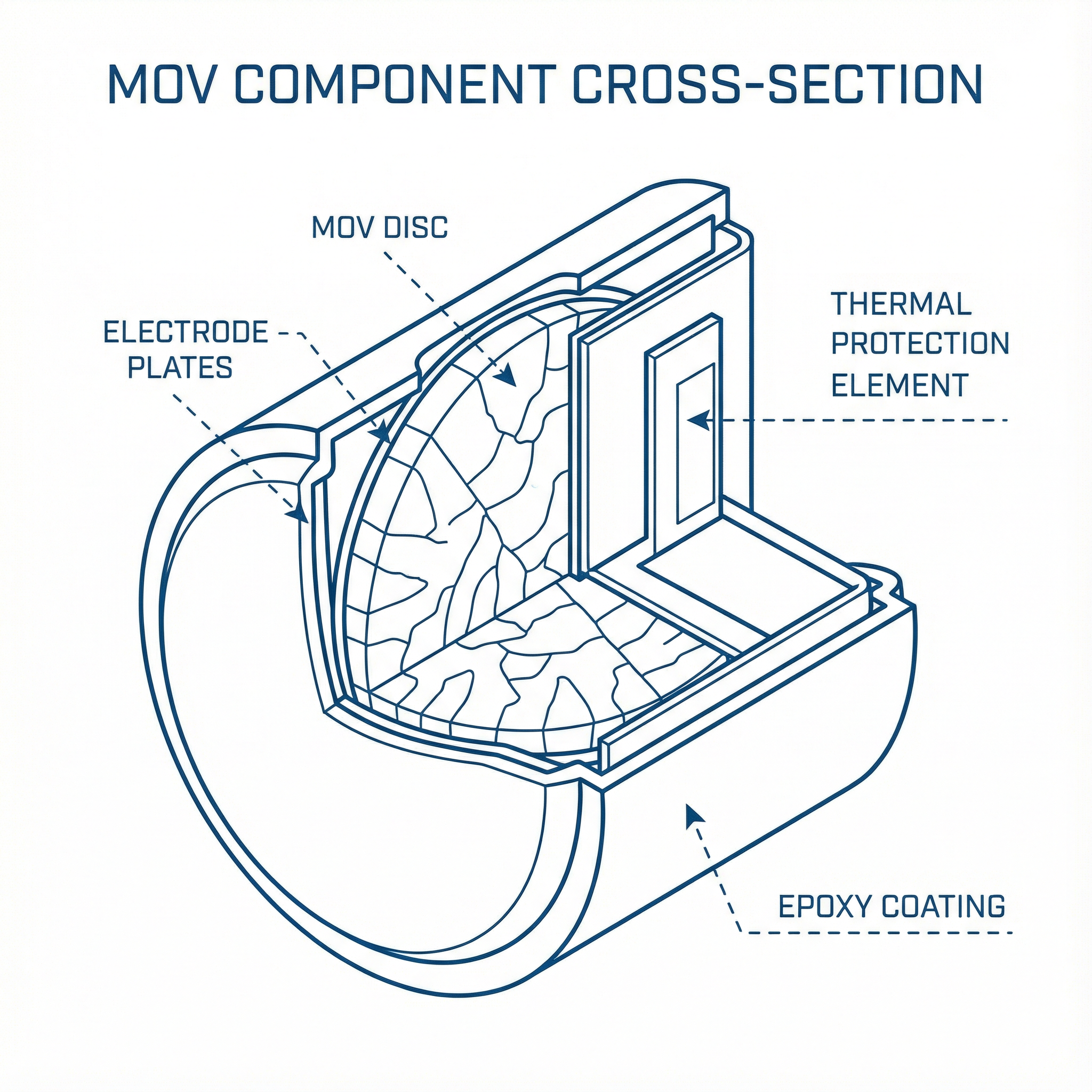
Именно здесь на помощь приходит современная техника. Осознав этот риск, производители разработали термозащищенный MOV (TPMOV). В TPMOV встроен тепловой размыкающий элемент - по сути, небольшой, точно рассчитанный предохранитель, - который находится в тесном контакте с диском MOV. Этот термоэлемент постоянно контролирует температуру MOV. Если MOV деградирует и начинает переходить в тепловой режим, возникающее при этом тепловое излучение заставляет термоэлемент разорвать соединение, надежно и надолго выводя поврежденный MOV из цепи, прежде чем он успеет катастрофически выйти из строя.
Когда происходит размыкание, срабатывает вторичный механизм: визуальный индикатор на корпусе SPD переключается с зеленого на красный. Красная лампочка на современном SPD означает, что внутренняя защита устройства сработала правильно, безопасно отключив износившийся компонент. Это преднамеренная, отказоустойчивая конструктивная особенность. Красный индикатор не указывает на активное перенапряжение; он указывает на то, что срок службы компонента, поглощающего перенапряжение, истек и он был безопасно отключен. Однако теперь ваше оборудование остается незащищенным и уязвимым для следующего скачка напряжения.
Теперь, когда мы знаем, что красный свет означает, что СПД выполнила свою работу и вышла из строя, следующий логичный вопрос: почему срок ее службы подошел к концу? Хотя иногда ответом может быть “просто пришло время”, выяснение причины крайне важно для обеспечения надежности системы и предотвращения преждевременных отказов. Существует три основные причины, по которым СПД активирует индикатор окончания срока службы.
Это самая распространенная и желательная причина выхода СПД из строя. Срок службы СПД измеряется не в годах, а в джоулях - единицах поглощенной им энергии. Каждый СПД имеет определенный номинал в джоулях, который представляет собой общее количество энергии перенапряжения, которое он может выдержать, прежде чем его внутренние компоненты выйдут из строя до неприемлемого уровня.
Считайте, что ваш SPD - это “губка для перенапряжения”. Большой скачок напряжения от близкого удара молнии может “заполнить губку” за один раз. Но чаще тысячи мелких, незаметных скачков напряжения от включения и выключения двигателей или переключения электросети постепенно заполняют ее в течение нескольких лет. Когда суммарная поглощенная энергия превысит емкость MOV, он перейдет в фазу окончания срока службы, тепловая защита отключит его, и лампочка загорится красным. В этом случае СПД отлично справляется со своими обязанностями в течение ожидаемого срока службы.
Эта причина представляет собой критическое, но устранимое несоответствие между СПД и электрической системой, которую он призван защищать. Каждый SPD имеет номинал, известный как максимальное непрерывное рабочее напряжение (Uc). Это значение представляет собой максимальное среднеквадратичное напряжение, которому устройство может подвергаться неограниченное время без протекания тока.
Если СПД с Uc При установке устройства с номиналом, меньшим, чем фактическое рабочее напряжение системы, MOV будет постоянно находиться в состоянии частичной проводимости. Например, установка SPD, рассчитанного на систему 240 В, в месте, где длительное напряжение составляет 277 В, приведет к тому, что MOV будет постоянно пропускать ток. Это не скачок напряжения, а постоянное перенапряжение, которое SPD интерпретирует как бесконечный скачок. MOV будет быстро нагреваться, что приведет к быстрому выходу из строя и вызовет срабатывание теплового разъединителя через несколько месяцев, недель или даже часов. Повторяющийся преждевременный отказ недавно установленного СПД - верный признак того, что устройство Uc Номинал неправильно подобран в соответствии с напряжением в системе.
Эффективность СПД зависит только от его установки. Наиболее важным аспектом установки является подключение к земле. Чтобы SPD работал, он должен иметь короткий низкоомный путь к земле для отвода энергии перенапряжения. Лучшие отраслевые практики, такие как IEEE и ведущие производители, требуют, чтобы импеданс заземления составлял 5 Ом или меньше. Длинные, петляющие провода заземления, “последовательные” соединения заземления или заземление на плохую опорную точку (например, металлическую водопроводную трубу, которая может быть отремонтирована с помощью непроводящего ПВХ) создают высокий импеданс.
При возникновении перенапряжения высокоомный заземляющий контур действует как узкое место, заставляя энергию перенапряжения искать другие пути - часто обратно в SPD или вниз по течению в защищаемое оборудование. Это может заставить MOV поглотить больше энергии, чем он был рассчитан, что приведет к более быстрому разрушению и преждевременному окончанию срока службы.
Кроме того, немаловажным фактором является качество самого SPD. В некачественных устройствах может использоваться дешевый припой или некачественные внутренние соединения. Механические и тепловые нагрузки при нормальной эксплуатации, транспортировке и установке могут привести к выходу из строя этих слабых мест, что приведет к размыканию цепи и ошибочному срабатыванию индикатора окончания срока службы.
| Коренная причина | Симптомы и индикаторы | Диагностическое действие | Решение |
|---|---|---|---|
| Превышен нормальный срок службы | СПД находится в эксплуатации 3-5+ лет. Объект находится в зоне с высоким уровнем перенапряжения (например, частые грозы). Других аномалий нет. | Проверьте дату установки в журналах технического обслуживания. Подтвердите возраст устройства. | Замените модуль SPD на новый, идентичный, с правильными техническими характеристиками. |
| Неправильная спецификация | Новая СПД выходит из строя преждевременно (через несколько дней, недель или месяцев). Неисправность может повторяться с многочисленными заменами. | Сразу после замены измерьте непрерывное напряжение в системе с помощью мультиметра с истинным среднеквадратичным значением. Сравните это значение с показаниями SPD Uc рейтинг, указанный на устройстве. | Приобрести и установить СПД с Uc номинал, соответствующий измеренному напряжению системы. Проведите аудит всей системы, чтобы найти другие неправильно указанные устройства. |
| Неправильная установка / качество | Преждевременные или прерывистые сбои. Визуальный осмотр может выявить длинные, свернутые или последовательно соединенные провода заземления. | Проведите физический аудит установки. Проверьте длину и путь фазных и заземляющих проводников. Если возможно, используйте тестер сопротивления заземления для измерения импеданса заземления. | Установите SPD в соответствии с рекомендациями производителя и IEEE, обеспечив короткий прямой путь к проверенному низкоомному заземлению. Всегда приобретайте SPD у надежных производителей, соответствующих стандартам UL 1449 и IEC 61643-11. |
Если вы столкнулись с SPD с красным индикатором, методичный подход обеспечит безопасность и долговременное решение. Не просто замените модуль и уйдите; используйте это как возможность проверить работоспособность вашей системы защиты.
Uc Рейтинг: Если сбой произошел преждевременно, немедленно убедитесь, что SPD Uc Номинал соответствует напряжению в системе. Проверьте напряжение с помощью мультиметра, как только система будет снова включена.Uc Например, в рейтинге эта информация важна для проведения аудита всей системы и будущих закупок. Хорошая документация превращает простую замену в ценные данные для прогнозируемого обслуживания.Uc Убедитесь, что номинал соответствует напряжению вашей системы, и выберите соответствующий тип SPD для данного места.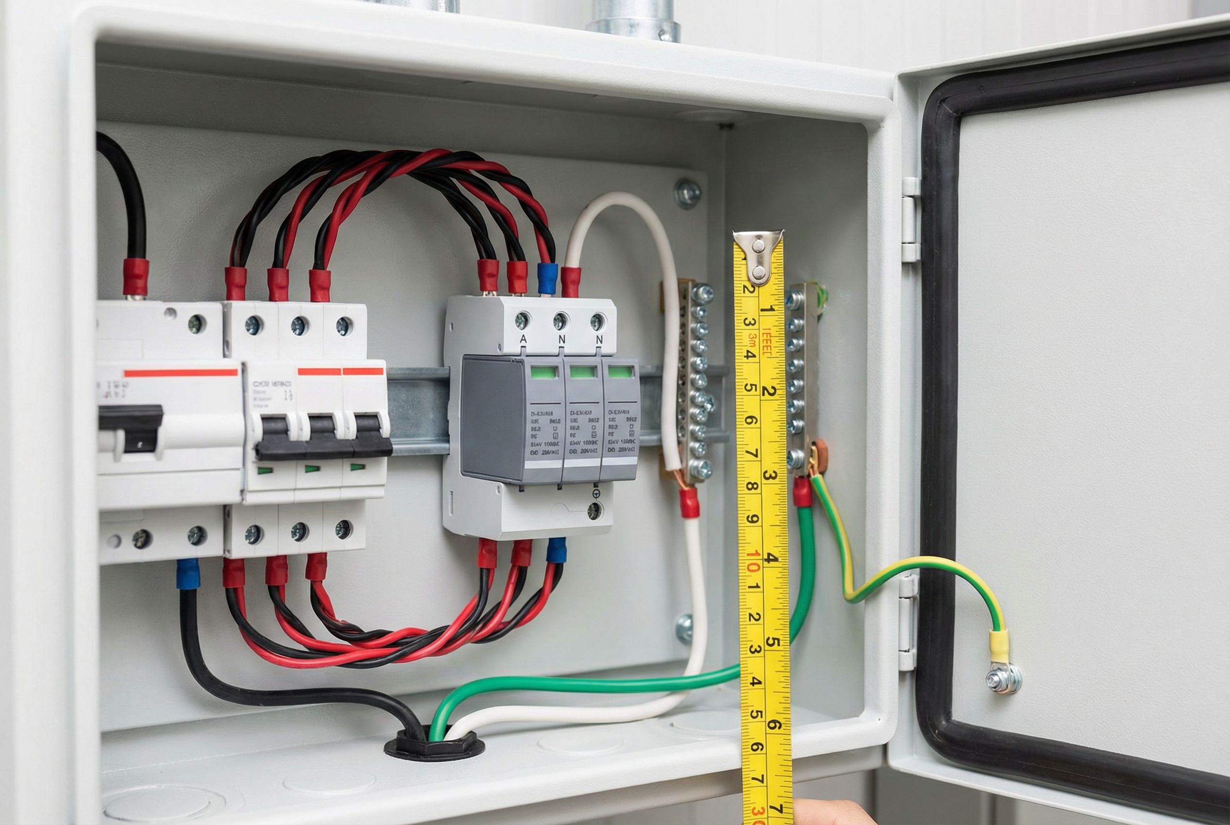
1. Могу ли я просто сбросить SPD с красным светом?
Нет. Красный индикатор указывает на то, что внутренний термопредохранитель физически и навсегда отключил компонент MOV. Это не автоматический выключатель, который можно сбросить. Необходимо заменить израсходованный модуль SPD.
2. В чем разница между красным и зеленым светом, который погас?
Это зависит от производителя. Для многих СПД красный свет - это особый индикатор окончания срока службы. Зеленый свет, который просто выключен, может указывать на потерю питания самого СПД. Всегда проверяйте, включен ли прерыватель и есть ли питание. Однако в некоторых моделях индикатором окончания срока службы является погасшая лампочка. Всегда обращайтесь к документации производителя, чтобы узнать конкретное значение индикаторов на вашем устройстве.
3. На какой срок рассчитан СПД?
Срок службы определяется количеством и величиной перенапряжений, которые он поглощает, а не фиксированным периодом времени. В спокойной электрической среде SPD может прослужить более десяти лет. На объекте с тяжелым промышленным оборудованием или в регионе с частыми грозами срок службы может составлять 3-5 лет или меньше.
4. Означает ли красный свет, что только что произошел опасный скачок напряжения?
Не обязательно. Красный свет означает, что Кульминация повреждений. Это может произойти от одного мощного скачка напряжения или от тысяч мелких скачков в течение многих лет. Тепловое отключение - это медленный процесс, вызванный нагревом, поэтому оно часто происходит при нормальном напряжении спустя долгое время после последнего повреждающего скачка напряжения.
5. Если индикатор горит красным, мое оборудование не защищено?
Да. Это самый важный момент. Красный свет означает, что защитный элемент больше не включен в цепь. SPD может по-прежнему пропускать энергию, действуя как простая распределительная коробка, но он обеспечивает нулевую защиту от скачков напряжения. Модуль следует заменить как можно скорее.
6. Почему правильное заземление так важно для СПД?
SPD работает, отводя энергию перенапряжения от вашего оборудования. Путь заземления является “маршрутом выхода” для этой энергии. Если этот путь заблокирован высоким сопротивлением (длинные провода, плохие соединения), энергии перенапряжения некуда деваться, и она либо повредит сам SPD, либо попадет на чувствительную электронику, что сводит на нет все предназначение устройства.
7. Что такое ‘Uc’ и как правильно его выбрать?Uc, Максимальное непрерывное рабочее напряжение - это наибольшее напряжение, которое может выдержать СПД в течение неограниченного времени. Чтобы выбрать правильный вариант, вы должны знать номинальное напряжение вашей системы и его возможные колебания. Например, в стандартной системе с расщепленной фазой 120/240 В напряжение от линии до нейтрали составляет 120 В, но вы должны выбрать SPD с Uc не менее 150 В, чтобы учесть нормальные колебания. Если вы не уверены, проконсультируйтесь с производителем СПД или квалифицированным инженером-электриком.
8. Не дешевле ли просто позволить оборудованию выйти из строя и заменить его?
С точки зрения совокупной стоимости владения (TCO) - почти никогда. Стоимость сменного модуля SPD составляет лишь малую часть стоимости одного ПЛК, VFD или сервера. Если учесть стоимость незапланированных простоев, потерь производства и трудозатрат на аварийное обслуживание, то надежная и хорошо обслуживаемая система защиты от перенапряжений обеспечивает чрезвычайно высокую рентабельность инвестиций.
Красный индикатор на вашем устройстве защиты от перенапряжения - это важная информация. Это ясное и простое сообщение: “Я выполнил свою работу по защите вашего имущества, и теперь мой срок службы окончен. Пожалуйста, замените меня”. Он означает успешную безотказную работу, а не опасную неисправность.
Понимая технические принципы деградации и термозащиты MOV, вы сможете с уверенностью диагностировать причину, будь то нормальный срок службы, неправильная спецификация или проблема установки. Эти знания позволят вам не ограничиваться простой заменой компонента, а создать более устойчивую и надежную электрическую систему. Относитесь к своей инфраструктуре защиты от перенапряжений как к критически важному, обслуживаемому активу. Проактивный осмотр, правильная спецификация и профессиональная установка - вот ключи к обеспечению безопасности и непрерывной работы всего объекта. Когда вы увидите красный свет, вы будете точно знать, что он означает и что нужно делать.
