웽양 공업구 웨칭 원저우 325000
근무 시간
월요일~금요일: 오전 7시~오후 7시
주말: 주말: 오전 10시 - 오후 5시
웽양 공업구 웨칭 원저우 325000
근무 시간
월요일~금요일: 오전 7시~오후 7시
주말: 주말: 오전 10시 - 오후 5시

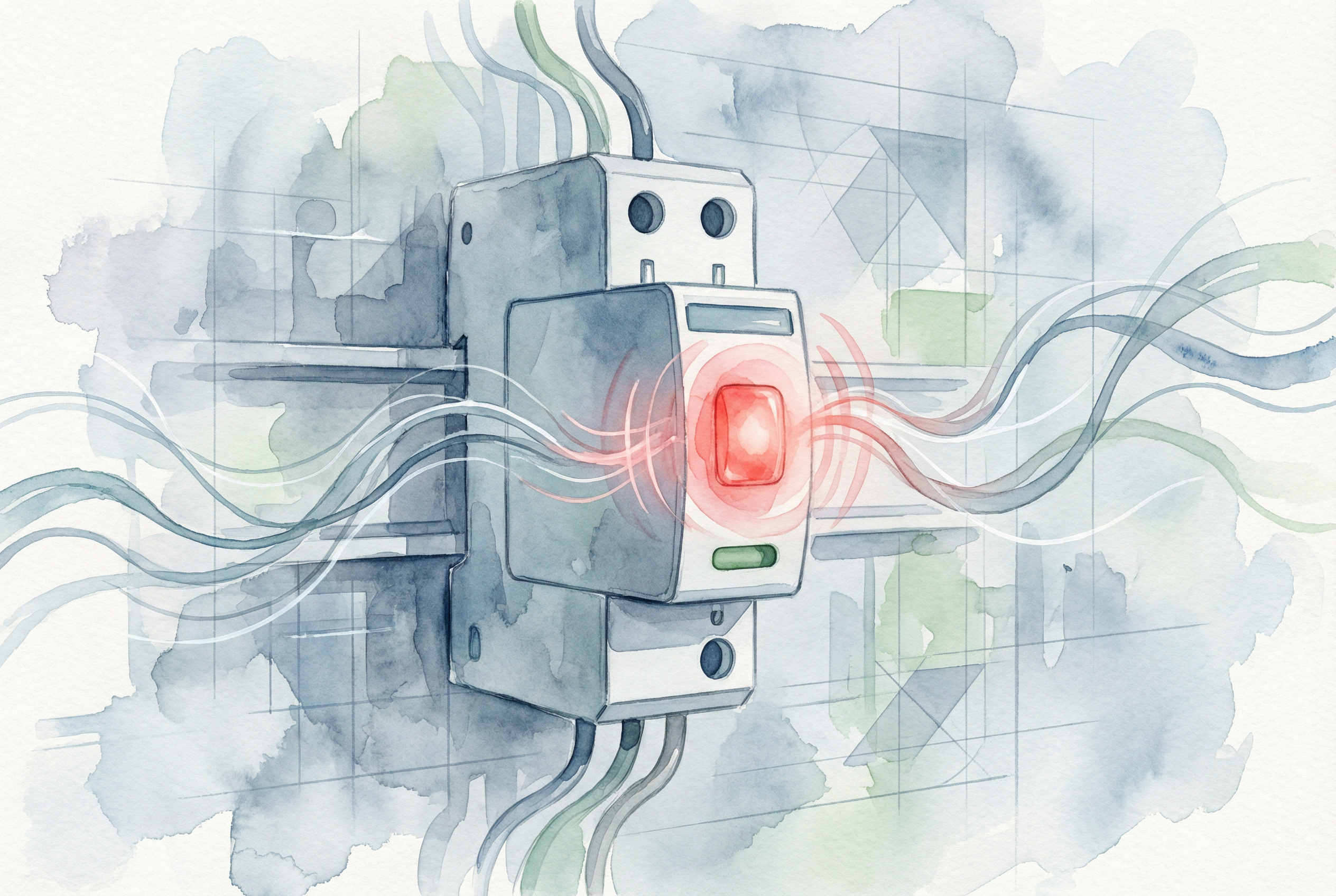
빠른 답변: An SPD red light or red status window commonly means that one or more surge-protection paths are no longer operational and the module may need replacement. However, indicator colours and alarm logic vary by manufacturer and model. Read the label and product manual before drawing a conclusion. If the meaning is uncertain, treat surge protection as unavailable and arrange inspection by a qualified electrician.
The connected equipment may continue to receive power even when the surge protective device has lost protection. A red indicator is therefore easy to overlook: the installation can appear to operate normally while its protection against transient overvoltage is reduced or absent.
This guide explains what the indicator can mean, the safe checks to make, why an SPD may fail early, and how to select a compatible replacement for AC and solar PV DC systems.

On many pluggable SPDs, a green window indicates that the protection module is operational and a red window indicates that its internal disconnector has isolated a failed or degraded protection component. Some products use LEDs, mechanical flags, audible alarms or remote contacts instead. Other devices show no light when power is missing or protection has failed. The exact manual is the deciding reference.
Manufacturer-specific behaviour matters. For example, some monitored devices use green, yellow and red states; yellow can provide an early replacement warning while protection remains available, and red indicates that replacement is required. Other products use a simple green/red window. This is why the colour alone should never be interpreted without the model documentation.
| Indicator or symptom | Likely meaning | 권장 조치 |
|---|---|---|
| Green indication | Protection is usually operational | Continue scheduled inspection; confirm the manual if the device has multiple poles or modes. |
| Red indication | A protection path may be disconnected or the module may require service | Identify the exact model, check all poles and arrange prompt inspection or replacement. |
| Yellow indication | Some monitored products use this as an advance warning | Follow the manufacturer’s replacement guidance; do not assume every yellow indicator has the same meaning. |
| Indicator off | Loss of supply, disconnected module, failed indicator or lost protection | Check the manual, upstream protective device and connections using a safe, approved procedure. |
| Remote alarm active | Auxiliary contact has changed state | Compare the contact logic with the wiring diagram and inspect the associated SPD module. |
Do not assume it is protected. Many SPDs are connected in parallel, so a disconnected protection element does not interrupt the load. Lights, machinery or an inverter can keep operating after the SPD has lost one or more protection modes. A multi-pole unit can also retain partial protection while one cartridge shows a fault.
The practical response is to check every pole or module, read any display or remote alarm, and verify the product instructions. Do not repeatedly energize a visibly damaged device. If there is heat, smell, smoke, cracking, soot or melted plastic, isolate the circuit according to the site safety procedure and obtain professional assistance.
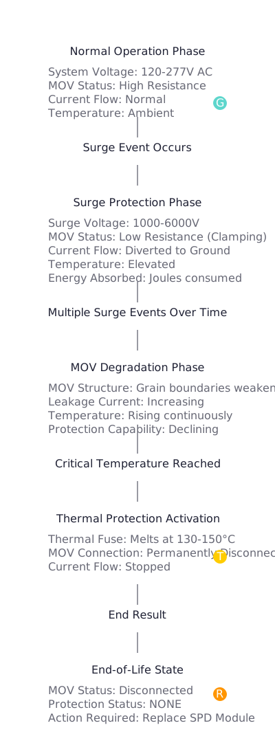
An SPD limits transient overvoltage by conducting surge current through nonlinear components such as metal-oxide varistors or spark gaps. Repeated impulses or an event beyond the device capability can change the protection component. Where provided, an internal disconnector isolates an unsafe or failed path and the status indicator changes.
Service life cannot be predicted from age or a marketing “joule” value alone. It depends on the surge environment, circuit conditions, SPD design, protection mode, temporary overvoltage performance, installation and maintenance history.
The maximum continuous operating voltage, marked Uc for many IEC AC products and Ucpv for PV applications, must suit the actual system and connection mode. A value that is too low can subject the SPD to abnormal stress during normal voltage variation or temporary overvoltage. Repeated premature failures require the system voltage, earthing arrangement and selection assumptions to be checked before another cartridge is installed.
A sustained abnormal voltage is different from a short transient surge. Neutral faults, incorrect wiring, insulation faults and other system conditions can impose stress outside the intended operating conditions. Simply inserting another cartridge may lead to another failure unless the underlying cause is found.
The SPD, upstream fuse or circuit breaker, prospective short-circuit current and manufacturer instructions must be considered together. An incorrect backup protective device can affect safety and fault clearing. Never increase a fuse or breaker rating solely to stop nuisance operation.
Long conductors, unnecessary loops, loose terminals, incorrect polarity, poor bonding and routing errors can reduce protection performance or create abnormal heating. Connection conductors should follow the product instructions and applicable installation rules. A single universal earth-electrode resistance value, such as “below 5 ohms,” is not a valid pass/fail rule for every SPD installation; surge-path impedance, bonding and conductor geometry also matter.
A plug-in cartridge may look simple to replace, but opening a distribution board exposes hazardous conductors and fault energy. Replacement should be performed only by someone competent and authorized for that installation.
Matching only the colour, width or nominal voltage is not enough. Confirm the following values from the installed product, circuit design and current manufacturer documentation:
Uc 또는 Ucpv: the maximum continuous operating voltage must suit the circuit and expected operating conditions.Iimp, In 및 Imax; these terms are not interchangeable.Up together with conductor length and equipment impulse withstand requirements.For product selection, compare KUANGYA’s AC 서지 보호 장치 및 DC 서지 보호 장치. For a deeper explanation of DC operation, see DC SPD의 작동 원리.
PV strings can remain energized whenever modules receive light. Do not unplug a cartridge or open a combiner box based only on an upstream AC isolation step. Follow the PV system isolation procedure and use personnel qualified for DC work.
A replacement PV SPD must be designed for photovoltaic DC service. Calculate maximum array open-circuit voltage at the lowest design temperature and select Ucpv accordingly. Also check polarity, protection mode, pole arrangement, external lightning protection, cable routing, backup protection and module/base compatibility.
Product requirements for PV SPDs are addressed by IEC 61643-31, while selection and application principles are addressed by IEC 61643-32. For related system design guidance, review the DC SPD for solar selection guide 및 PV combiner box guide.
IEC 61643-11:2025 specifies requirements and test methods for SPDs connected to AC low-voltage power systems, while IEC 61643-12 covers AC selection and application principles. Refer to the current applicable edition, local wiring rules and the manufacturer’s documentation. See the official IEC 61643-11:2025 overview 및 IEC 61643-12 overview. Manufacturer examples also show why model-specific interpretation matters: Schneider Electric’s Resi9 guidance identifies a red flag as a replacement condition for that product.
Usually not. On many products, the red indication follows operation of an internal disconnector or loss of a protection module. Confirm the manual; a failed cartridge normally requires replacement rather than resetting.
No. A parallel-connected SPD can lose protection while the load remains energized. Normal equipment operation does not prove that surge protection is available.
Only when the manufacturer permits it and the replacement cartridge is approved for that exact base and product series. Investigate the cause first if the failure was premature or repeated.
Possible causes include incorrect Uc or Ucpv, temporary overvoltage, wrong system configuration, wiring errors, unsuitable backup protection, abnormal fault conditions or a surge beyond the device capability.
There is no universal service life in years. Surge exposure, electrical conditions, product design, environment and installation all affect life. Use the status indication and manufacturer’s maintenance guidance.
No. Some devices use a mechanical red window, some use LEDs, and some combine green, yellow and red states or remote contacts. Always use the exact product manual.
It indicates a condition that needs attention. The installation may have lost surge protection, and visible heat, smell, smoke or damage requires urgent isolation and professional inspection.
No, unless it is specifically rated and approved for that DC application. PV circuits require suitable DC ratings, Ucpv selection, polarity and system coordination.
If you need help matching an SPD to an AC distribution board or PV system, contact KUANGYA with the system voltage, earthing arrangement, SPD markings, application, fault-current data and clear photographs of the installed base and module.

