温州市岳陽工業区 325000
勤務時間
月曜日~金曜日:午前7時~午後7時
週末午前10時~午後5時
温州市岳陽工業区 325000
勤務時間
月曜日~金曜日:午前7時~午後7時
週末午前10時~午後5時

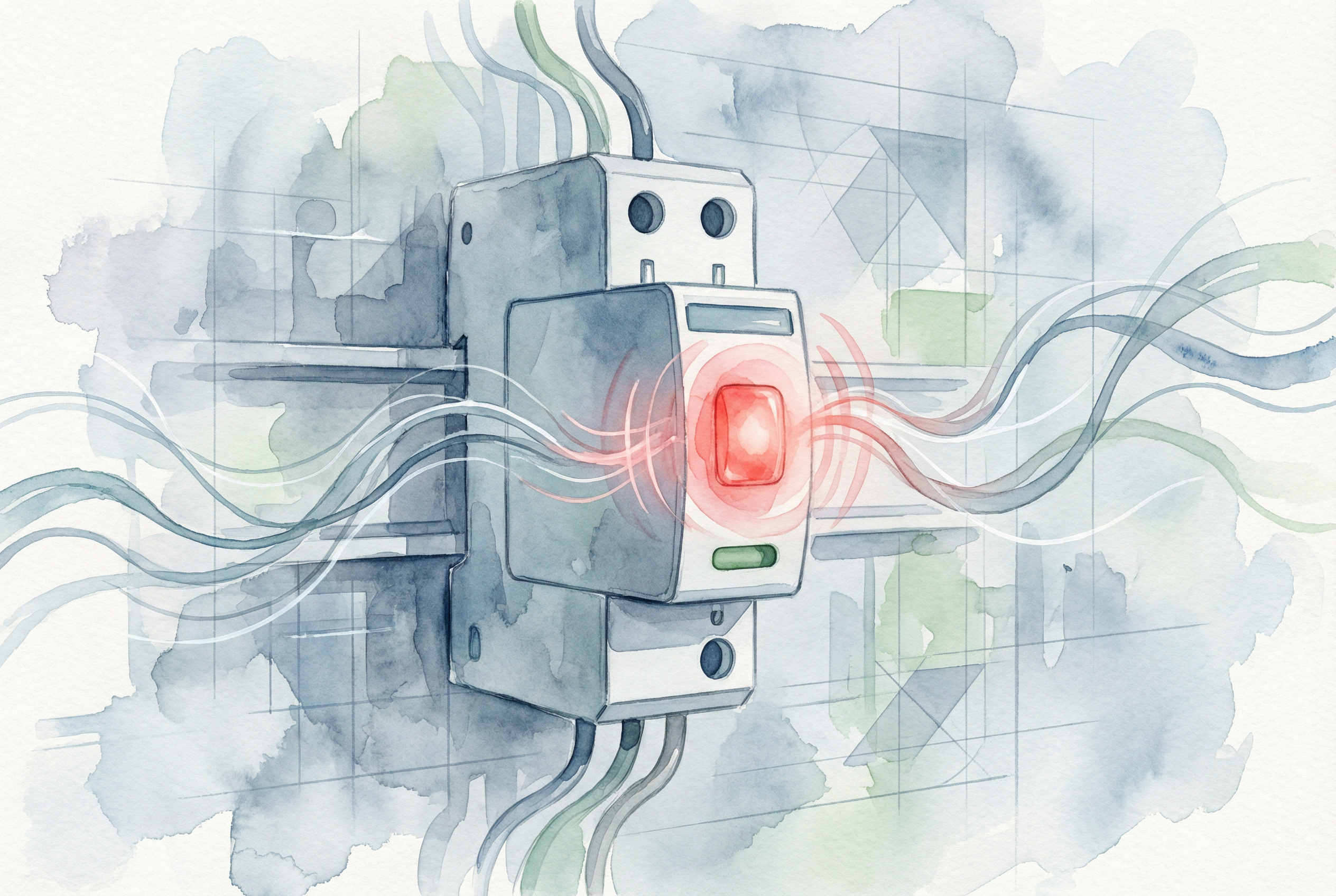
クイックアンサー: アン SPD red light usually means that one or more protection paths are no longer available, but indicator logic varies by manufacturer and model. Check the device label and manual first. Do not assume that every red indicator means the same fault.
If the status window has changed from green to red, treat the circuit as potentially unprotected and arrange prompt inspection by a qualified electrician. Do not open an energized panel or test live terminals unless you are trained, authorized, and using the required protective equipment.
This guide explains common causes, safe checks, replacement decisions, and the extra parameters required for solar DC SPDs, including Ucpv, maximum array open-circuit voltage at the lowest design temperature, SPD type, and module/base compatibility.
To understand what the red light signifies, we first need to look inside the SPD. The workhorse component of most SPDs is the Metal Oxide Varistor, or MOV. Think of an MOV as a highly sensitive, voltage-controlled gate. Under normal voltage conditions, it remains in a high-resistance state, allowing power to flow uninterrupted to your equipment. However, when a voltage surge occurs—whether from a distant lightning strike or internal equipment switching—the MOV instantly transitions to a low-resistance state, diverting the harmful excess energy safely to the ground.

This process happens in microseconds, protecting your electronics from the damaging overvoltage. However, this protection comes at a cost. Each surge the MOV absorbs degrades it slightly. Over time, after absorbing one large surge or thousands of smaller ones, the MOV’s internal structure wears down. This degradation can lead to a dangerous condition known as “thermal runaway.” A worn-out MOV may begin to leak current even under normal system voltage, causing it to heat up continuously. If left unchecked, this process could lead to the MOV overheating, smoking, and creating a significant fire or short-circuit hazard.
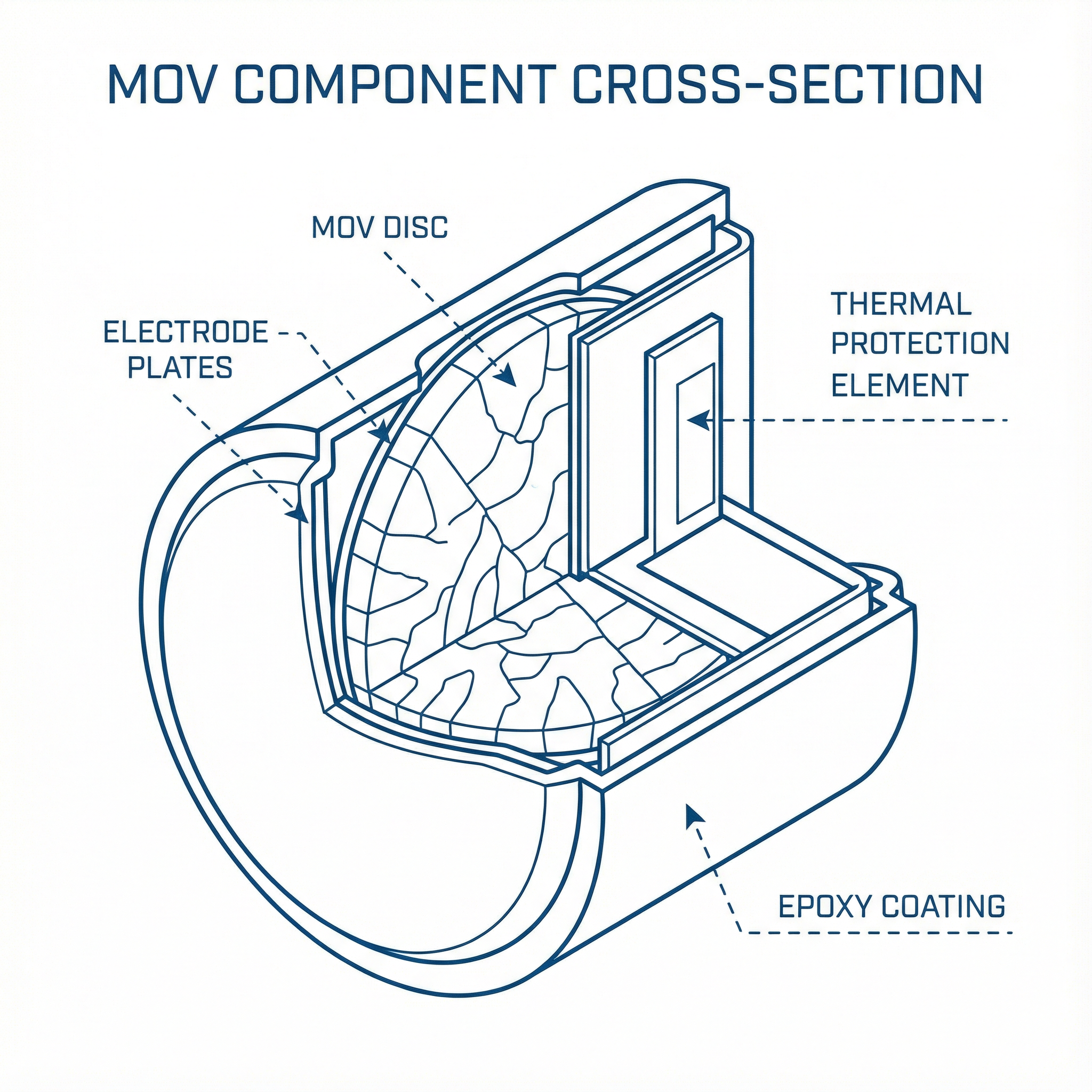
This is where modern engineering steps in. Recognizing this inherent risk, manufacturers developed the Thermally Protected MOV (TPMOV). A TPMOV integrates a thermal disconnecting element—essentially a small, precisely designed fuse—that is in intimate contact with the MOV disk. This thermal element constantly monitors the MOV’s temperature. If the MOV degrades and begins to enter thermal runaway, the resulting heat buildup will cause the thermal element to sever the connection, safely and permanently taking the compromised MOV out of the circuit before it can fail catastrophically.
When the thermal disconnector operates, many pluggable SPDs change their mechanical status window from green to red. However, indicator colors and contact logic are manufacturer-specific. Confirm the meaning on the device label or datasheet. A red or fault indication commonly means that at least one protection path is unavailable; the protected equipment may still receive power but should not be assumed to have full surge protection.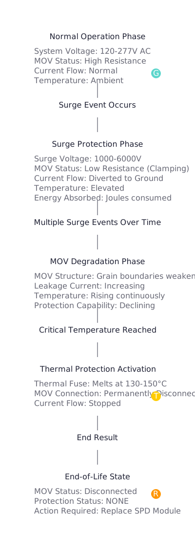
Now that we know the red light means the SPD has done its job and retired, the next logical question is: why did it reach its end of life? While the answer can sometimes be “it was simply its time,” investigating the cause is crucial for ensuring system reliability and avoiding a pattern of premature failures. There are three primary reasons an SPD will activate its end-of-life indicator.
This is the most common and desirable reason for an SPD to fail. The lifespan of an SPD isn’t measured in years, but in joules—the unit of energy it has absorbed . Every SPD has a specific joule rating, which represents the total amount of surge energy it can handle before its internal components degrade to an unacceptable level.
Think of your SPD as a “surge sponge.” A large surge from a nearby lightning strike might “fill the sponge” all at once. More commonly, thousands of small, imperceptible surges from motors turning on and off or utility grid switching will gradually fill it over several years. Once the cumulative energy absorbed exceeds the MOV’s capacity, it enters the end-of-life phase, the thermal protector disconnects it, and the light turns red. In this case, the SPD has performed its duty perfectly over its expected operational lifespan.
This cause represents a critical, yet avoidable, mismatch between the SPD and the electrical system it’s meant to protect. Every SPD has a rating known as the Maximum Continuous Operating Voltage (Uc). This value represents the maximum RMS voltage the device can be subjected to indefinitely without conducting current
If an SPD with a ウク rating lower than the system’s actual operating voltage is installed, the MOV will be in a state of partial conduction continuously. For example, installing an SPD rated for a 240V system in a location that experiences sustained voltages of 277V will force the MOV to constantly leak current. This is not a surge condition; it’s a persistent overvoltage that the SPD interprets as a never-ending surge. The MOV will heat up rapidly, leading to a swift thermal runaway and causing the thermal disconnector to trip in a matter of months, weeks, or even hours. A recurring, premature failure of a newly installed SPD is a strong indicator that the device’s ウク rating is incorrectly matched to the system voltage.
An SPD is only as effective as its installation. The most critical aspect of installation is the ground connection. For an SPD to work, it must have a short, low-impedance path to ground to divert surge energy. SPD performance depends strongly on short, straight connecting conductors, correct bonding, and compliance with the manufacturer’s installation instructions and applicable local standards. A universal “5 ohms or less” rule should not be used to judge every SPD installation: earth-electrode resistance and high-frequency surge-path impedance are different quantities. Long loops, sharp bends, loose connections, and poor bonding can increase the protective voltage at the equipment.
When a surge occurs, a high-impedance ground path acts like a bottleneck, forcing the surge energy to seek other paths—often back into the SPD or downstream into your protected equipment. This can force the MOV to absorb more energy than it was designed for, leading to a much faster degradation and premature end-of-life.
Furthermore, the quality of the SPD itself is a factor. Poorly manufactured devices may use cheap solder or have inadequate internal connections. The mechanical and thermal stresses of normal operation, transportation, and installation can cause these weak points to fail, leading to an open circuit that incorrectly triggers the end-of-life indicator
| 根本原因 | Symptoms & Indicators | Diagnostic Action | ソリューション |
|---|---|---|---|
| Normal Lifespan Exceeded | Device has been in service for an unknown period or has experienced significant surge activity. Age alone does not prove end-of-life. | Check the installation date in maintenance logs. Confirm the device’s age. | Replace the SPD module with a new one of the identical, correct specification. |
| Incorrect Specification | New SPD fails prematurely (days, weeks, or months). The failure may be recurring with multiple replacements. | Have a qualified electrician verify the system voltage and configuration using an approved procedure, then compare the result with the SPD’s ウク rating and manufacturer requirements. Do not probe energized conductors unless trained and authorized. | Procure and install an SPD with a ウク rating appropriate for the measured system voltage. Perform a system-wide audit to find other incorrectly specified devices. |
| Improper Installation / Quality | Premature or intermittent failures. Visual inspection may reveal long, coiled, or daisy-chained ground wires. | Perform a physical audit of the installation. Check the length and path of the phase and ground conductors. If possible, use an earth ground resistance tester to measure the grounding impedance. | Re-install the SPD according to manufacturer and IEEE guidelines, ensuring a short, direct path to a verified low-impedance ground. Always procure SPDs from reputable manufacturers compliant with UL 1449 and IEC 61643-11 standards. |
When you encounter an SPD with a red light, a methodical approach ensures safety and a lasting solution. Do not simply replace the module and walk away; use it as an opportunity to verify the health of your protection system.
ウク Rating: If the failure was premature, immediately confirm that the SPD’s ウク rating is appropriate for the system voltage. Use a multimeter to check the voltage as soon as the system is re-energized.ウク rating, for instance, this information is vital for system-wide audits and future purchasing. Good documentation turns a simple replacement into valuable data for predictive maintenance.ウク rating to ensure it matches your system voltage, and select the appropriate SPD Type for the location.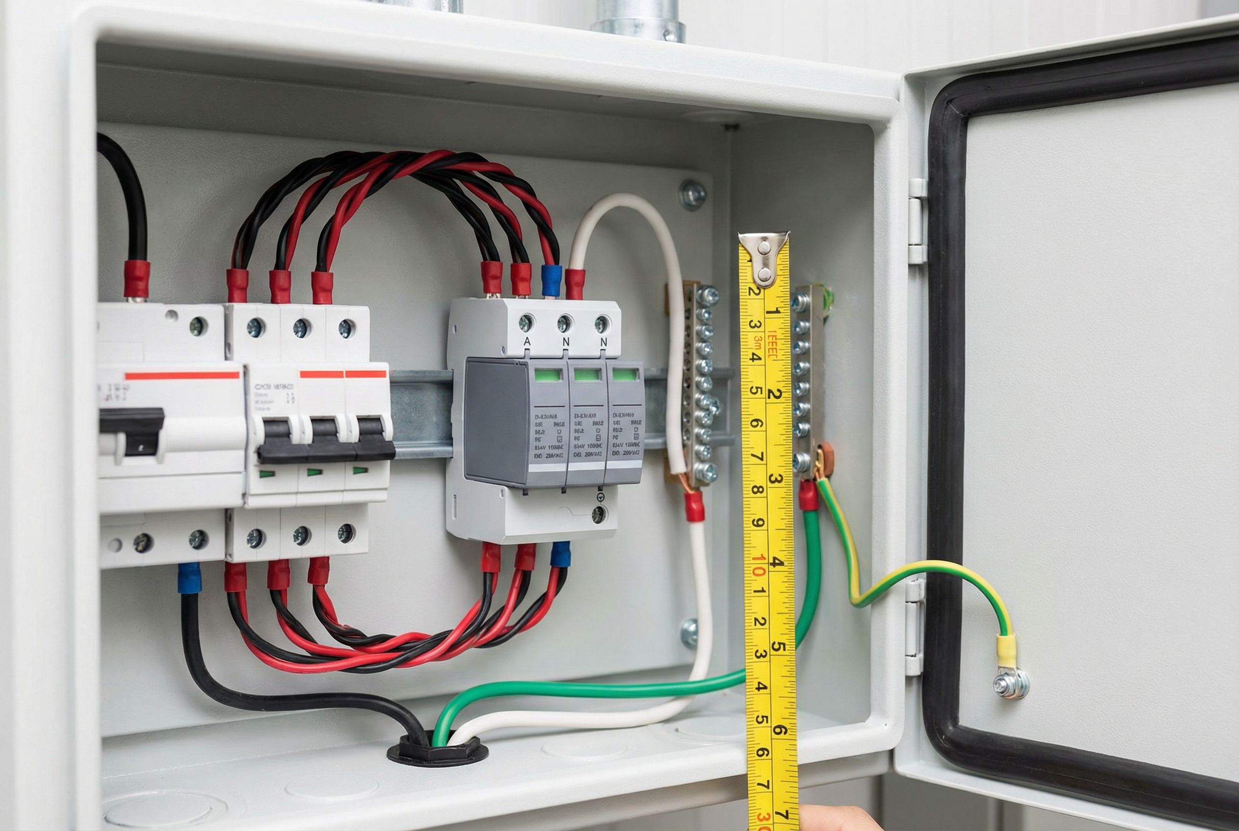
For a photovoltaic DC circuit, do not select a replacement by AC voltage or physical appearance alone. Verify that the replacement is specifically rated for PV DC service and complies with the applicable product standard, such as IEC 61643-31. System selection and installation should follow the project design and applicable guidance, such as IEC 61643-32.
Ucpv: it must be suitable for the maximum PV array open-circuit voltage calculated at the site’s lowest design temperature—not only the nominal operating voltage.1. Can I just reset an SPD with a red light?
No. The red light indicates that an internal thermal fuse has physically and permanently disconnected the MOV component. It is not a circuit breaker that can be reset. The spent SPD module must be replaced.
2. What’s the difference between a red light and a green light that has gone out?
This depends on the manufacturer. For many SPDs, a red light is the specific indicator for end-of-life. A green light that is simply off may indicate a loss of power to the SPD itself. Always check that the upstream breaker is on and power is present. However, on some models, an extinguished light is the end-of-life indicator. Always consult the manufacturer’s documentation for the specific meaning of the indicators on your device.
3. How long is an SPD supposed to last?
SPD service life is not a fixed number of years. It depends on surge exposure, temporary overvoltage, system configuration, environment, product design, and installation. Use the status indicator, remote contact where provided, inspection records, and the manufacturer’s maintenance guidance rather than replacing an SPD only because it has reached a stated age.
4. Does a red light mean a dangerous surge just happened?
Not necessarily. The red light signifies the culmination of damage. This could be from one massive surge or from thousands of tiny surges over many years. The thermal disconnection is a slow process caused by heat, so it often happens under normal voltage conditions long after the last damaging surge occurred.
5. If the light is red, is my equipment unprotected?
Possibly. On many devices a red status window means that one or more protection paths have disconnected, so full protection cannot be assumed. Multi-pole units may retain partial protection, while other models use different indicator logic. Identify the exact model, consult its manual, and arrange prompt replacement or testing by a qualified person.
6. Why is proper grounding so critical for an SPD?
An SPD works by diverting surge energy away from your equipment. The ground path is the “exit route” for this energy. If the path is blocked by high resistance (long wires, poor connections), the surge energy has nowhere to go and will either damage the SPD itself or flow downstream to your sensitive electronics, defeating the entire purpose of the device.
7. What is ‘Uc’ and how do I choose the right one?ウク, or Maximum Continuous Operating Voltage, is the highest voltage the SPD can withstand indefinitely. To choose the right one, you must know the nominal voltage of your system and its potential fluctuations. For example, on a standard 120/240V split-phase system, the line-to-neutral voltage is 120V, but you should choose an SPD with a ウク of at least 150V to account for normal swells. If you are unsure, consult the SPD manufacturer or a qualified electrical engineer.
8. Is it cheaper to just let equipment fail and replace it?
From a Total Cost of Ownership (TCO) perspective, almost never. The cost of a replacement SPD module is a tiny fraction of the cost of a single PLC, VFD, or server. When you factor in the costs of unplanned downtime, lost production, and emergency maintenance labor, a robust and well-maintained surge protection system provides an extremely high return on investment.
A red or fault indication on a Surge Protective Device requires prompt attention, but it does not have one universal meaning. On many SPDs it indicates that an internal protective path has disconnected; on others, indicator behavior differs. Confirm the exact model documentation, treat protection as uncertain, and have a qualified person correct the cause and replace the appropriate module when required.
By understanding the technical principles of MOV degradation and thermal protection, you can confidently diagnose the cause, whether it’s normal end-of-life, an incorrect specification, or an installation issue. This knowledge empowers you to move beyond simply replacing a component and instead to build a more resilient and reliable electrical system. Treat your surge protection infrastructure as a critical, maintainable asset. Proactive inspection, correct specification, and professional installation are the keys to ensuring the safety and continuous operation of your entire facility. When you see that red light, you’ll know exactly what it means and exactly what to do.

