WengYang Industrial Zone Yueqing Wenzhou 325000
Horas de trabalho
De segunda a sexta-feira: das 7h às 19h
Fim de semana: 10:00 - 17:00
WengYang Industrial Zone Yueqing Wenzhou 325000
Horas de trabalho
De segunda a sexta-feira: das 7h às 19h
Fim de semana: 10:00 - 17:00

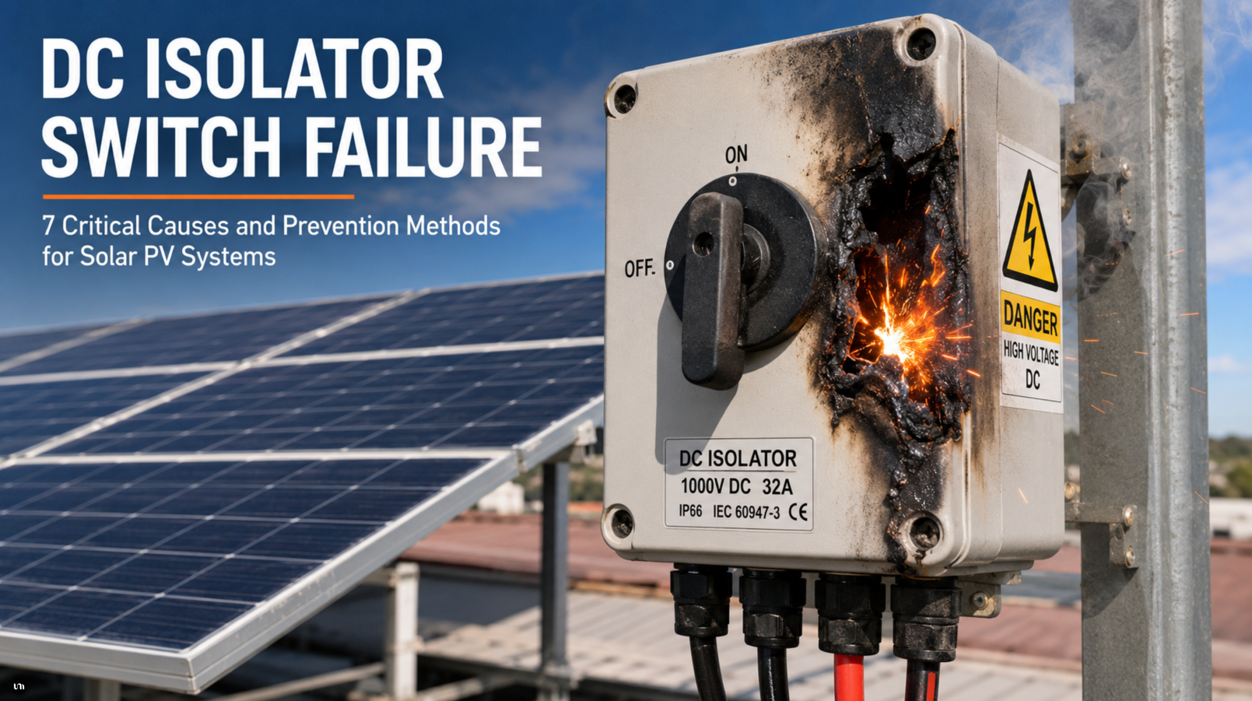
A DC isolator is one of the most important manual safety devices in a solar photovoltaic system. It allows technicians to disconnect specific DC circuits during inspection, emergency response or equipment replacement.
However, the isolator can also become a source of overheating, arcing and fire when it is incorrectly selected, poorly installed or exposed to unsuitable environmental conditions.
The key conclusion is simple: most cases of DC isolator switch failure are not caused by one dramatic event. They normally develop from excessive contact resistance, incorrect voltage selection, loose conductors, moisture ingress, high ambient temperature or gradual mechanical deterioration.
A reliable protection strategy must therefore combine correct component selection, controlled installation, regular inspection and coordinated use of fuses, surge protective devices, circuit breakers and fire protection equipment.
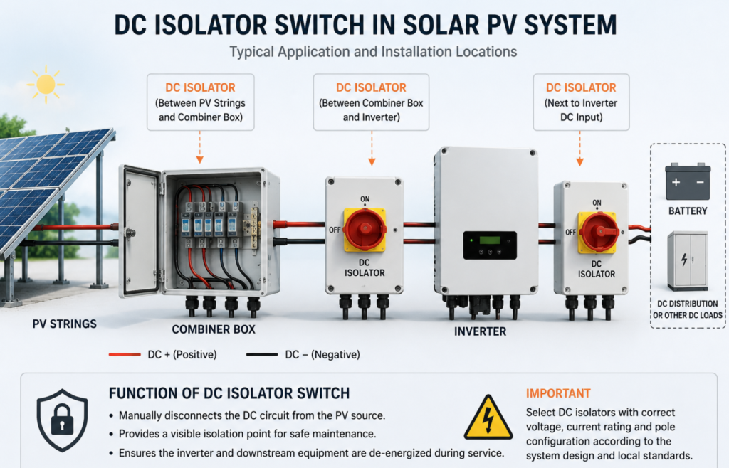
A DC isolator switch, also called a DC disconnect switch or PV isolator, is a manually operated device used to create electrical separation between different sections of a direct-current circuit.
In a solar PV system, isolators may be installed between:
Its main purpose is isolation. It gives maintenance personnel a controlled way to separate equipment from the DC source.
A DC isolator is not automatically a substitute for a fuse or circuit breaker. Depending on the product design, it may be capable of switching normal operating current, but it should not be assumed to provide overcurrent, short-circuit or surge protection.
IEC 60947-3 covers switches, disconnectors, switch-disconnectors and fuse-combination units used in circuits rated up to 1,000 V AC or 1,500 V DC. The current consolidated edition includes the 2025 amendment.
| Dispositivo | Função primária | Typical event addressed | Automatically operates? |
|---|---|---|---|
| Isolador CC | Manual circuit isolation | Maintenance or emergency isolation | Não |
| fusível gPV | Overcurrent and reverse-current interruption | String fault or parallel-string current | Sim |
| Disjuntor CC | Switching and overcurrent protection | Overload or short circuit | Sim |
| DC SPD | Surge limitation | Lightning-induced or switching surge | Sim |
| Arc-fault detector | Detects abnormal arcing | Series or parallel arc fault | Sim |
| Cabinet fire suppression device | Controls an early fire inside an enclosure | Localized cabinet fire | Automatically, depending on design |
Each device addresses a different electrical risk. Removing one layer creates a gap that the remaining components may not be able to cover.
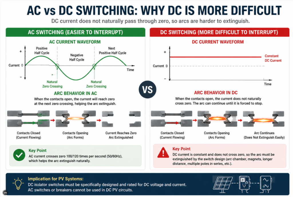
Direct current behaves differently from alternating current during switching and fault conditions.
An alternating-current waveform repeatedly passes through zero. This can help an AC arc extinguish. In a high-voltage DC circuit, current does not naturally cross zero in the same way. Once an arc is established, it can remain active as long as sufficient voltage and current are available.
Research on PV fire safety notes that DC circuitry can produce sustained arcs capable of igniting nearby combustible materials. Disconnect switches can reduce the number of energized conductors, but they must be correctly designed and installed for the application.
This is why an ordinary AC switch should never be treated as a replacement for a properly rated PV DC isolator.
A failing isolator may initially produce only a small amount of heat. As the internal temperature rises, the following sequence can develop:
The system may continue generating power during this process. PV modules remain energized when exposed to light, even when the AC side of the inverter has been disconnected. This makes safe isolation and emergency response more complicated than in many conventional AC installations.
DC isolator problems are not always visible from outside the enclosure. Maintenance teams should therefore look for electrical, thermal and mechanical warning signs.
| Warning sign | Possible cause | Required response |
|---|---|---|
| Brown or black discoloration | Sustained overheating or arcing | Isolate and replace the affected device |
| Melted enclosure surface | Severe internal heating | Shut down the circuit using an approved procedure |
| Cheiro de queimado | Insulation or polymer degradation | Treat as an urgent electrical hazard |
| Unusual clicking or crackling | Intermittent internal arcing | Do not continue operating the switch |
| Hot cable terminals | Loose connection or incorrect conductor size | Inspect terminal preparation and torque |
| Difficult rotary operation | Mechanical wear or internal deformation | Replace rather than force the mechanism |
| Water inside the enclosure | Failed sealing or cable-gland installation | Correct the enclosure and replace damaged components |
| Repeated inverter DC faults | Unstable connection or insulation problem | Perform electrical and insulation testing |
| Localized thermal-camera hotspot | Increased resistance | Investigate before visible damage develops |
| Cracked housing or UV degradation | Environmental aging | Replace with a suitable outdoor-rated device |
A thermal image showing one terminal significantly hotter than the others is particularly important. The total current may still be within the device rating, but a high-resistance joint can create intense localized heating.
The first major cause of DC isolator switch failure is selecting a device that does not have sufficient DC voltage capability.
The operating voltage printed on an inverter or module datasheet is not always the maximum voltage that can appear in the array. PV module open-circuit voltage increases as cell temperature decreases.
For this reason, the maximum design voltage must be calculated using:
A string designed around nominal operating conditions may exceed the voltage capability of the isolator during a cold, clear morning.
Assume that one module has:
If low temperature increases the module open-circuit voltage, the actual maximum string voltage may rise well above 1,000 V. A 1,000 V DC isolator may therefore be unsuitable, even though the normal operating voltage appears lower.
The engineer must calculate the maximum possible voltage rather than choosing the switch based only on the inverter’s normal MPPT voltage.
An isolator with insufficient voltage capability may not provide adequate internal separation when opened. The arc can bridge the contact gap or track across contaminated insulating surfaces.
This can lead to:
For modern utility-scale and commercial PV systems, 1,500 V DC architecture requires isolators specifically designed and tested for that voltage class.
Loose terminals are among the most common causes of overheating in electrical equipment.
The power converted into heat at a connection is related to current and resistance. Even a relatively small increase in resistance can produce significant heating when the circuit carries current for several hours each day.
Common installation problems include:
A connection may initially appear secure but loosen after repeated heating and cooling cycles.
“Hand tight” is not a repeatable installation standard. Two installers can apply very different force using the same screwdriver.
The correct procedure is to:
Re-tightening terminals without following the manufacturer’s instructions can also be risky. Some terminals are not intended to be repeatedly disturbed after installation.
A multi-pole DC isolator relies on a specific internal switching arrangement.
Connecting the incoming and outgoing conductors to the wrong terminals can change the way voltage is divided across the contacts. In some products, the poles must be connected in series or according to a defined polarity diagram to achieve the stated voltage rating.
Possible wiring errors include:
The correct number of poles also depends on the PV system design, inverter topology, grounding arrangement and local electrical requirements.
In some PV systems, both the positive and negative conductors must be treated as live. The installer should not assume that opening only one conductor creates a completely safe working condition.
The wiring diagram supplied with the exact isolator model must take priority over assumptions based on another brand or product family.
A physically similar enclosure does not guarantee an identical internal contact arrangement.
Outdoor DC isolators are continuously exposed to environmental stress.
Even when the enclosure has a suitable IP rating, water can enter because of poor installation details rather than a defective enclosure.
Typical entry points include:
Once moisture enters, it can cause corrosion, contamination and insulation deterioration. A thin conductive path may form across internal surfaces, especially where dust and salt are present.
An enclosure can remain externally sealed and still develop internal condensation.
During the day, the enclosure heats up. At night, the internal air cools. Repeated temperature changes can draw humid air into the enclosure and allow water to condense on cooler internal surfaces.
This is particularly relevant in:
The enclosure material, ventilation strategy, drainage arrangement and installation orientation must therefore be evaluated together.
An IP rating alone does not guarantee reliable performance under every environmental condition.
An isolator can overheat even when the system current appears to be below the nameplate rating.
The rated current may depend on:
A device rated at a particular current under laboratory conditions may have a lower practical capacity when installed inside a small enclosure exposed to direct sunlight.
Outdoor electrical enclosures can become much hotter than the surrounding air.
For example, a rooftop isolator may be exposed to:
These factors can raise the internal temperature beyond the assumptions used during basic product selection.
The designer should not simply select an isolator with the same current rating as the module short-circuit current.
The calculation should consider:
A larger current rating does not correct a bad terminal connection, but adequate current margin can reduce unnecessary thermal stress when all other installation conditions are correct.
DC isolators contain moving contacts, springs, shafts and operating mechanisms. These components can deteriorate through repeated operation, contamination or excessive force.
Possible mechanical failure modes include:
A switch-disconnector should open its contacts quickly and decisively. A slow or incomplete movement can allow an arc to remain between the contacts for longer.
An isolator should not be repeatedly used as a general-purpose control switch unless the product has been selected for the required switching duty.
Frequent operation under high current can accelerate:
Personnel should also avoid operating a switch that is visibly damaged, extremely hot or producing abnormal noise. Moving the handle may disturb an already unstable connection.
Handling defective switches and isolating damaged PV equipment should be performed by qualified electrical personnel following the site’s shutdown procedure.
Not every isolator failure is caused by incorrect installation. Product defects, unsuitable materials and internal design weaknesses can also contribute.
Official Australian safety notices have documented DC isolators with internal faults capable of producing high-resistance connections, overheating and fire. Australian authorities reported that recalled Avanco isolators had been associated with at least 57 property fires.
This does not mean every PV isolator is unsafe. It demonstrates why procurement should be based on verified technical evidence rather than enclosure appearance or the lowest unit price.
Potential concerns include:
Even a correctly certified device can deteriorate after years of exposure to:
A certification report describes performance when the product is new and tested under specified conditions. It does not remove the need for suitable installation and long-term inspection.
Safety recalls provide valuable engineering lessons because they show how a small internal defect can develop into a property-level hazard.
Australian regulators identified models of solar DC isolators in which internal faults could create high-resistance connections. These faults were capable of causing the isolators to overheat or catch fire. Owners of affected systems were advised to shut down the systems and arrange replacement by qualified personnel.
The broader lesson for EPC contractors is not limited to one brand or country.
A reliable project should include:
Product approval should not end after the purchase order is issued.
Correct selection requires more than matching the number of poles and the current printed on the front label.
| Item de seleção | What to verify | Erro comum |
|---|---|---|
| Maximum DC voltage | Calculated cold-weather array voltage | Using normal operating voltage |
| Corrente nominal | Maximum expected continuous current plus required factors | Matching only module Imp |
| Switching duty | Suitability for the intended PV DC application | Assuming any DC switch can interrupt load |
| Pole arrangement | Wiring diagram and isolation requirements | Copying another model’s diagram |
| Grau de proteção do invólucro | Dust, water and installation environment | Relying only on the IP number |
| Temperature range | Minimum and maximum site conditions | Ignoring solar enclosure heating |
| Capacidade do terminal | Cable type and conductor cross-section | Forcing oversized cables into terminals |
| Certificação | Applicable standard and valid test evidence | Accepting a logo without documentation |
| Resistência aos raios UV | Outdoor material suitability | Using indoor plastic outdoors |
| Traceability | Model, batch and manufacturer identification | Purchasing unmarked products |
| Locking function | Maintenance and safety requirements | Ignoring lockout procedures |
| Acessórios | Compatible glands, jumpers and mounting parts | Mixing components from unrelated products |
Use the module open-circuit voltage and temperature coefficient to determine the worst-case string voltage.
The selected isolator voltage must remain suitable under the lowest expected module temperature.
The isolator should be designed and tested for the intended DC application.
Do not rely on an AC rating or assume that a high AC voltage rating provides equivalent DC performance.
Review the manufacturer’s data for ambient-temperature and enclosure derating.
A 32 A or 40 A nameplate does not necessarily mean the device can carry that current continuously in every installation condition.
Confirm:
For outdoor installations, consider:
The supplier should be able to provide:
Even a high-quality isolator can fail when installed incorrectly.
The installer should confirm:
Follow this sequence:
Commissioning should include:
NREL guidance emphasizes that post-installation hazards can evolve over time, including ground faults, arc faults and damaged wiring that may lead to fire. Commissioning should therefore establish a baseline for future inspection rather than being treated as a one-time formality.
The required frequency depends on system size, environment, equipment criticality and local regulations.
| Inspection item | Routine visual inspection | Detailed maintenance |
|---|---|---|
| Enclosure discoloration | Every site visit | Anualmente |
| Water or condensation | Every site visit | Before and after wet season |
| Cable-gland condition | Every site visit | Anualmente |
| Handle operation | According to safe procedure | Anualmente |
| Imagens térmicas | Under representative load | A cada 6 a 12 meses |
| Terminal condition | When safely isolated | According to manufacturer |
| Insulation resistance | After abnormal event or scheduled shutdown | Periodically |
| Product recall status | Procurement and maintenance review | At least annually |
| Labels and identification | Every site visit | Anualmente |
| UV degradation | Every site visit | Anualmente |
Thermal imaging is most useful when:
A temperature difference is often more useful than a single absolute temperature.
For example, one terminal that is substantially hotter than adjacent terminals carrying similar current may indicate:
Thermal imaging identifies symptoms. It does not replace electrical isolation and physical inspection.
An overheating isolator should be treated as an electrical hazard.
Do not immediately open the enclosure or repeatedly operate the handle.
A visibly damaged isolator should not be returned to service merely because the terminal has been tightened.
Heat may already have affected:
A DC isolator works best as part of a layered protection strategy.
A gPV fuse protects PV strings against specified overcurrent and reverse-current conditions.
It does not replace an isolator because:
The fuse rating must coordinate with module maximum-series-fuse requirements, conductor capacity and available reverse current.
DC SPD (Dispositivo Solar de Proteção contra Surtos DC) | Kuangya
A DC surge protective device limits transient overvoltage caused by lightning-related or switching events.
An SPD does not prevent a loose terminal from overheating. However, it helps reduce insulation stress and damage caused by transient voltage.
The SPD must be coordinated with:
A DC circuit breaker may combine switching with overcurrent protection, depending on its design and certification.
It should not automatically be treated as interchangeable with an isolator. The required isolation characteristics, switching category, fault rating and lockout function must be evaluated.
Arc-fault detection may identify electrical signatures associated with abnormal arcing.
It is useful because some series arcs do not produce enough overcurrent to operate a conventional fuse. Nevertheless, arc-fault detection should complement—not replace—good connectors, controlled torque, suitable isolators and preventive maintenance.
A compact automatic fire suppression device may be installed inside suitable enclosed electrical cabinets as a final protective layer.
Its purpose is to control an early fire after prevention measures have failed.
It does not:
For open rooftop isolators, the priority remains correct product selection, weather protection, installation and electrical maintenance. Cabinet fire suppression is most relevant where DC isolators and other components are installed inside enclosed combiner boxes, distribution cabinets or control panels.
Before approving a DC isolator supplier, EPC contractors should ask the following questions.
| Pergunta | Por que é importante |
|---|---|
| Is the product specifically rated for the required DC voltage? | AC and DC switching performance are different |
| Is the stated current subject to temperature derating? | Outdoor enclosures may operate at high temperature |
| Which standard has been used for testing? | Confirms the technical basis of the rating |
| Can the supplier provide valid certification details? | Reduces the risk of unsupported claims |
| What wiring arrangement is required? | Incorrect pole connection can reduce breaking capability |
| What is the terminal torque? | Essential for installation control |
| Which conductor types are approved? | Fine-stranded and solid conductors may require different preparation |
| Is the enclosure suitable for outdoor UV exposure? | Prevents premature housing degradation |
| Can batch numbers be traced? | Necessary for quality investigations and recalls |
| Is installation training available? | Reduces field errors |
| Are replacement units dimensionally compatible? | Simplifies future maintenance |
| Has the design been reviewed for 1,500 V systems? | High-voltage PV requires dedicated evaluation |
The lowest purchase price should not be the only procurement criterion. The cost of replacing an installed isolator across hundreds of strings can greatly exceed the initial component saving.
No, not unless the manufacturer explicitly provides a suitable DC rating for the required voltage, current and wiring arrangement.
DC arcs are more difficult to interrupt because the current does not naturally pass through zero in the same way as AC. An AC-only switch may fail to provide safe separation in a PV circuit.
Common causes include loose terminals, damaged contacts, excessive current, incorrect cable preparation, corrosion, mechanical wear and high ambient temperature.
A thermal hotspot should be investigated even when the total circuit current is below the nominal rating.
Não necessariamente.
PV modules continue producing voltage when exposed to light. Turning off the inverter’s AC supply does not automatically remove voltage from the PV array cables.
The complete manufacturer and site shutdown procedure must be followed.
It depends on the device design and rating, but an isolator should not automatically be assumed to provide short-circuit protection.
Fuses or circuit breakers are generally used to interrupt defined fault currents. The isolator provides controlled circuit separation.
This depends on the system grounding arrangement, inverter design and applicable electrical rules.
In many ungrounded PV systems, both conductors may be live relative to earth and require simultaneous isolation. The design must follow the applicable standard and equipment instructions.
The inspection interval should be based on the project environment and risk level.
For outdoor commercial and utility PV systems, visual inspections during routine site visits and thermal imaging every 6–12 months provide a practical starting point. Harsh coastal, desert or industrial environments may require more frequent checks.
Nem sempre.
When overheating has already discolored or deformed the terminal, internal contacts or insulation may also be damaged. Replacement is normally safer than simply tightening a heat-damaged device.
The conductor and cable insulation should also be inspected.
The required IP rating depends on the installation location and exposure.
However, product rating alone is not sufficient. Cable-gland selection, mounting orientation, gasket condition, condensation and drainage must also be considered.
A DC isolator is primarily intended to provide manual isolation.
A DC circuit breaker is designed to interrupt specified overcurrent or short-circuit conditions and may also provide switching and isolation functions when appropriately rated.
The two devices should not be treated as automatically interchangeable.
It may help control an early fire when the isolator is installed inside a properly designed enclosed cabinet.
However, it is a final protective layer. It cannot compensate for an incorrectly rated isolator, loose terminal, water ingress or poor wiring.
Before energizing a solar PV DC isolator, confirm that:
DC isolator switch failure is usually the final result of several smaller weaknesses developing over time.
An incorrectly selected voltage rating may reduce the switch’s ability to interrupt the circuit. A loose terminal may create resistive heating. Water ingress may corrode the contacts. High ambient temperature may accelerate material aging. Mechanical deterioration may then prevent the isolator from opening quickly and completely.
Preventing failure requires more than purchasing a device with a suitable number printed on its label.
A reliable solar PV project should combine:
The DC isolator is only one component, but its position in the power circuit makes its reliability critical. Correct engineering, installation and maintenance can prevent a small connection defect from developing into prolonged downtime, equipment damage or an electrical fire.

