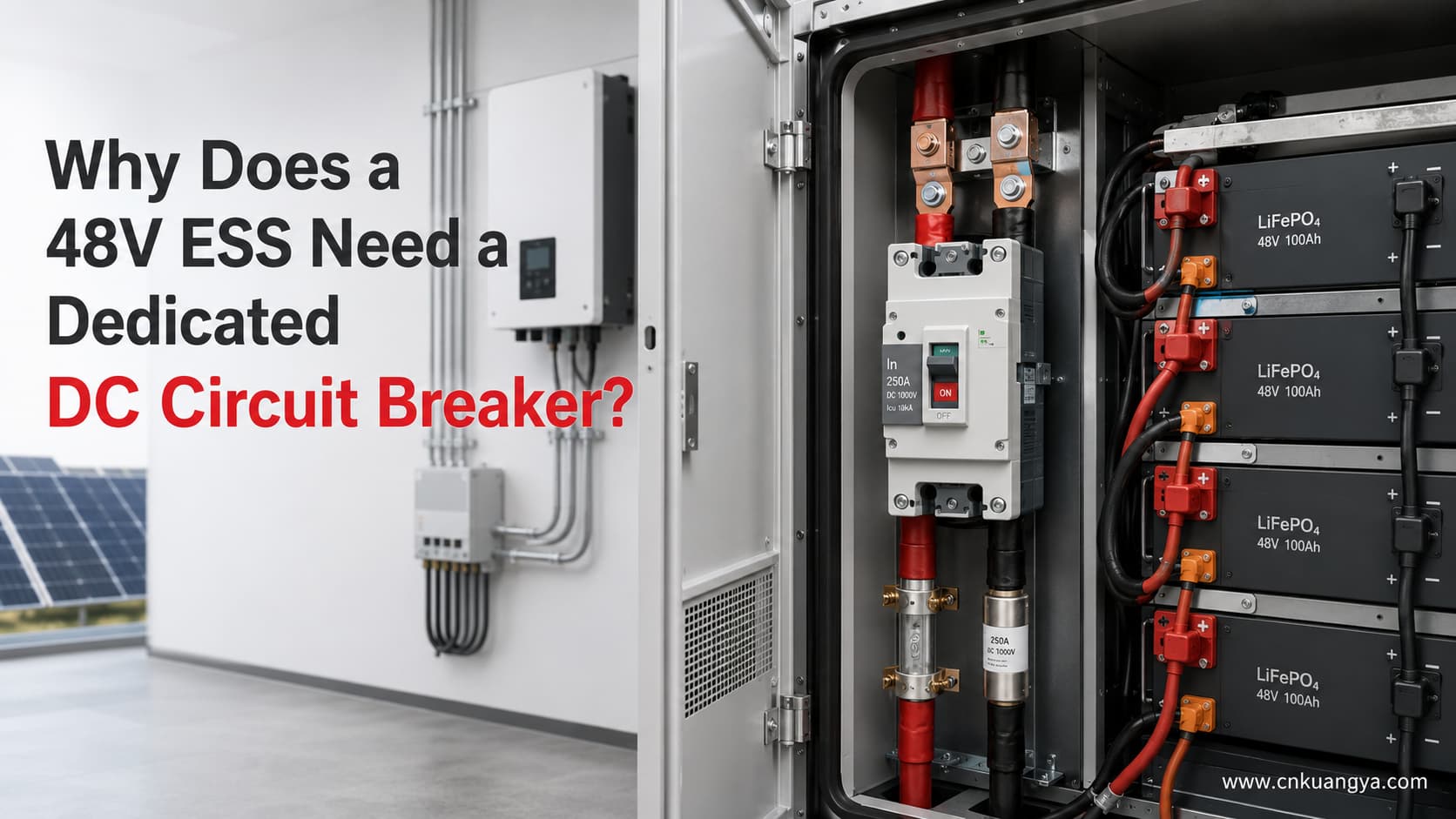
Pourquoi un système de stockage d'énergie (ESS) 48V nécessite-t-il un disjoncteur CC dédié ?

Un système de stockage d'énergie 48V est généralement qualifié de système basse tension. Cependant, basse tension ne signifie pas faible risque électrique.

Lorsqu'un parc de batteries 48V alimente un onduleur haute puissance, le courant côté batterie peut facilement dépasser 100A, 200A, voire 250A. Ce courant traverse les câbles de batterie, les jeux de barres, les bornes, les contacteurs, les fusibles, les disjoncteurs et les conducteurs d'entrée de l'onduleur.

En cas de surcharge, de court-circuit, de connexion desserrée, de défaut d'isolement ou de défaut sur une branche de batterie, la chaleur et l'énergie de défaut générées peuvent endommager les conducteurs et l'équipement.

C'est pourquoi un dispositif correctement sélectionné disjoncteur CC 48V est souvent installé dans le cadre du système de protection côté batterie.

Cependant, le disjoncteur ne doit pas être sélectionné uniquement en fonction de la puissance de l'onduleur. La conception complète doit prendre en compte :

  • La plage de tension de fonctionnement de la batterie
  • Le rendement de l'onduleur
  • Courant continu maximal de charge et de décharge
  • Le courant de crête temporaire
  • Les limites de la batterie et du BMS
  • La capacité de courant des câbles et des jeux de barres
  • Le courant de court-circuit disponible
  • La tension nominale en courant continu du disjoncteur
  • Pouvoir de coupure en courant continu (DC)
  • Courbes de déclenchement
  • Configuration des pôles
  • Schéma de mise à la terre
  • Sens du courant
  • Déclassement en fonction de la température ambiante

Pour une explication plus détaillée sur la tension, le courant, le pouvoir de coupure, la configuration des pôles et la coordination des disjoncteurs pour ESS, consultez notre guide complet de sélection des disjoncteurs CC pour ESS.

Réponse rapide

Un système ESS de 48V nécessite un système de protection contre les surintensités CC dédié, car une batterie basse tension peut toujours délivrer un courant très élevé.

Une sélection adéquate disjoncteur CC 48V peut fournir :

  • Protection contre les surcharges pour les câbles de batterie
  • Protection contre les courts-circuits dans la limite de son pouvoir de coupure vérifié
  • Déconnexion manuelle côté batterie
  • Fonctionnement réarmable après certains défauts
  • Coordination avec le BMS, le contacteur, le fusible, l'onduleur et les branches de batterie

Le BMS surveille normalement la tension de la batterie, la tension des cellules, le courant, la température et les limites de fonctionnement. Selon l'architecture du système, il peut commander l'onduleur, le chargeur, le contacteur ou un dispositif de commutation externe pour interrompre le courant.

Cela ne fait pas automatiquement du BMS un substitut à un dispositif de protection contre les surintensités dédié.

Un BMS, un contacteur, un fusible et un disjoncteur MCCB CC remplissent des fonctions différentes.

BMS, contacteur, fusible et disjoncteur CC : quelle est la différence ?

DispositifFonction principaleSurveille automatiquement les cellules de batterie ?Peut interrompre le courant de défaut ?Réarmable ?Fonction d'isolation manuelle
BMS (Système de gestion de batterie)Surveille et contrôle les conditions de fonctionnement de la batterieOuiGénéralement via un autre dispositif de commutationOuiGénéralement non
ContacteurConnecte ou déconnecte électriquement la batterieNonUniquement dans les limites de son pouvoir de coupure CC spécifiéOuiNormalement pas utilisé comme sectionneur manuel principal
FusibleAssure une protection unique contre les surintensités et les courts-circuitsNonOui, dans les limites de sa tension nominale CCNonNon
DC MCCBAssure une protection contre les surcharges et les courts-circuitsNonOui, dans la limite de son pouvoir de coupure CC vérifiéOuiPossible lorsqu'il est dimensionné pour la commutation ou le sectionnement
Interrupteur-sectionneurAssure l'isolation manuelleNonPas nécessairement adapté à l'interruption de défautOuiOui
BMS contactor fuse and DC MCCB functions in a 48V ESS
Le BMS, le contacteur, le fusible et le disjoncteur boîtier moulé (MCCB) CC assurent différentes fonctions de surveillance, de commutation et de protection dans un système de stockage d'énergie (ESS).

La documentation des BMS modernes montre que le BMS peut surveiller la tension, le courant et la température des cellules, puis envoyer des commandes aux charges, aux chargeurs ou aux contacteurs. Un exemple pratique est le Manuel du Victron VE.Bus BMS NG, qui décrit la surveillance au niveau des cellules ainsi que l'activation ou la désactivation de la charge et de la décharge en fonction de l'état de la batterie. Certains systèmes utilisent un contacteur comme dispositif de sécurité secondaire en cas de défaillance des fonctions de contrôle normales du BMS. Cela confirme que la surveillance, le contrôle, la commutation et la protection contre les surintensités sont des fonctions distinctes qui doivent être coordonnées.

La conclusion correcte est :

Ces dispositifs remplissent des fonctions différentes et doivent être coordonnés dans le cadre de la conception globale de la protection du système de stockage d'énergie (ESS).

Pour une comparaison ciblée de la vitesse de fonctionnement, de la capacité de réarmement, de la maintenance et des applications typiques, lisez notre Guide comparatif : disjoncteur CC vs fusible CC.

Pourquoi basse tension ne signifie pas faible courant

La relation fondamentale entre la puissance, la tension et le courant est :

P = V × I

Par conséquent :

I = P ÷ V

Pour un onduleur, l'efficacité doit également être prise en compte. Une estimation plus utile du courant côté batterie est :

I₍DC₎ = P₍sortie AC₎ ÷ (V₍batterie₎ × η)

Où ?

  • I₍DC₎ est le courant batterie estimé en ampères
  • P₍sortie AC₎ est la puissance de sortie AC réelle de l'onduleur en watts
  • V₍batterie₎ est la tension réelle de la batterie en charge
  • η est le rendement de l'onduleur exprimé sous forme décimale

Par exemple, un rendement de 95 % est saisi comme 0.95.

Cette formule estime le courant de batterie en régime permanent. Elle ne prend pas en compte toutes les variables possibles, telles que la consommation en veille de l'onduleur, la consommation du système de contrôle, les pertes dans les câbles, les surcharges temporaires, les pics de démarrage, l'ondulation du courant ou les limites de fonctionnement spécifiques au fabricant.

Courant de batterie calculé pour des charges de 5 kW et 10 kW

Les calculs suivants supposent un rendement de l'onduleur de 95 %.

Puissance de sortie CATension de la batterie en chargeRendement supposéCalculCourant de batterie estimé
5 000 W48V95%5 000 ÷ (48 × 0,95)109,6 A
5 000 W44 V95%5 000 ÷ (44 × 0,95)119,6 A
5 000 W42 V95%5 000 ÷ (42 × 0,95)125,3 A
10 000 W48V95%10 000 ÷ (48 × 0,95)219,3 A
10 000 W44 V95%10 000 ÷ (44 × 0,95)239,2 A
10 000 W42 V95%10 000 ÷ (42 × 0,95)250,6 A
48V ESS battery current comparison for 5kW and 10kW inverter loads
À 48V et avec un rendement d'onduleur de 95 %, une charge de 5 kW nécessite environ 110 A, tandis qu'une charge de 10 kW nécessite environ 219 A.

Ces calculs démontrent pourquoi l'étiquette nominale “ 48V ” ne suffit pas.

A 10kW inverter drawing from a battery at 48V may require approximately 219A under the stated assumptions. If the battery voltage falls to 42V, the calculated current rises to approximately 251A.

This is before adding design allowances for operating conditions, auxiliary consumption, cable losses, temporary overload, or manufacturer-specific requirements.

Therefore, a 250A battery breaker for an inverter is not automatically suitable for every 10kW, 48V system.

Why Battery Voltage Falls Under Load

A battery described as “48V” does not remain at exactly 48.0V throughout charging and discharging.

The actual operating voltage depends on:

  • Battery chemistry
  • Number of cells in series
  • State of charge
  • Charge or discharge current
  • Cell temperature
  • Internal resistance
  • Cable voltage drop
  • BMS limits
  • Inverter low-voltage settings

A published 51.2V LiFePO4 battery example has a nominal voltage of 51.2V, a recommended charging voltage between 56V and 56.8V, and an end-of-discharge voltage of 44.8V. This demonstrates why both maximum charging voltage and lower discharge voltage must be considered when selecting a breaker.

The breaker voltage rating must be higher than the maximum battery-system voltage that can appear across it.

The current calculation should also be checked at the lowest permitted operating voltage, because lower battery voltage produces higher current for the same power output.

Real Engineering Case 1: A 48V 5kVA Inverter/Charger

Consider a published 48V inverter/charger with the following manufacturer data:

ParamètresPublished value
Model class48V / 5,000VA
Continuous real output at 25°C4,000W
Battery input voltage range38–66V
Maximum efficiency96%
Peak power9,000W
Recommended DC fuse200A
Recommended cable for 0–5m70mm²
Recommended cable for 5–10m120mm²
48V 5kVA inverter system with 200A DC fuse and battery cables
A published 48V 5kVA inverter example recommends a 200A DC fuse even though the calculated continuous battery current is below 100A.

These values are taken from the manufacturer’s MultiPlus-II and Quattro-II installation manual rather than estimated from the product name.

At 48V and 96% efficiency:

I = 4,000 ÷ (48 × 0.96)

I ≈ 86.8A

At 42V and 96% efficiency:

I = 4,000 ÷ (42 × 0.96)

I ≈ 99.2A

A buyer might see the calculated 87–99A current and immediately choose a 100A or 125A breaker.

However, the manufacturer recommends a 200A DC fuse for this particular inverter/charger.

Why is the recommendation higher than the basic continuous-current calculation?

Because the final protection requirement may need to account for:

  • Peak inverter power
  • Temporary overload
  • Inrush current
  • Fuse time-current characteristics
  • Battery cable configuration
  • Nuisance-trip prevention
  • Internal inverter design
  • Manufacturer testing
  • Thermal operating conditions

This case demonstrates an important rule:

The power formula is a starting point, not the final breaker size.

The inverter manufacturer’s approved installation instructions, battery limits, cable capacity, and protective-device characteristics must all be reviewed.

It would also be incorrect to copy the manufacturer’s 200A fuse recommendation and automatically replace it with a 200A MCCB. A fuse and an MCCB may have different operating curves, short-circuit performance, let-through energy, and interruption characteristics.

Real Engineering Case 2: A 48V 10kVA Inverter/Charger

Now consider a larger published inverter/charger.

ParamètresPublished value
Model class48V / 10,000VA
Continuous real output at 25°C8,000W
Continuous real output at 40°C7,000W
Continuous real output at 65°C6,000W
Battery input voltage range38–66V
Maximum efficiency95%
Peak power18,000W
Recommended DC fuse400A
Recommended cable for 0–5m2 × 50mm² per polarity
Recommended cable for 5–10m2 × 70mm² per polarity
48V 10kVA inverter system with 400A DC fuse and parallel battery cables
A published 48V 10kVA inverter example uses a 400A DC fuse and parallel battery cables, showing why power calculations alone cannot determine protection size.

The same manufacturer manual publishes 8,000W as the continuous real output at 25°C, although the model is identified as 10,000VA. although the model is identified as 10,000VA. It also recommends a 400A DC fuse and two parallel 50mm² conductors per positive and negative connection for cable runs up to 5m.

At 48V and 95% efficiency:

I = 8,000 ÷ (48 × 0.95)

I ≈ 175.4A

At 42V and 95% efficiency:

I = 8,000 ÷ (42 × 0.95)

I ≈ 200.5A

A simple calculation might suggest that a 250A DC MCCB should be enough.

However, the manufacturer recommends a 400A fuse for this particular unit.

That does not mean every similar 48V inverter requires a 400A protective device. It means that the protection selection for this specific inverter must follow its tested and published installation requirements.

This real example also shows why an engineer must distinguish between:

  • VA rating
  • Continuous real power in watts
  • Peak power
  • Calculated continuous battery current
  • Recommended protective-device rating
  • Protective-device trip curve
  • Cable configuration

A product marked “10kVA” is not necessarily delivering 10kW of continuous real power under every condition.

Real Engineering Case 3: Two Parallel 51.2V LiFePO4 Batteries

Consider two identical 51.2V, 100Ah LiFePO4 batteries connected in parallel.

The published specification for each battery includes:

Parameter per batteryPublished value
Nominal voltage51.2V
Nominal capacity100Ah
Nominal energy5.12kWh
Maximum continuous discharge current100A
Maximum pulse discharge current200A for 10 seconds
End-of-discharge voltage44.8V
Charging voltage56–56.8V

The battery manufacturer also states that fuse selection should not exceed the lowest current rating among the battery, cable, and system limits.

With two identical batteries in parallel, the theoretical combined values become:

Combined parameterCalculRésultat
Nominal capacity100Ah × 2200Ah
Nominal energy5.12kWh × 210.24kWh
Maximum continuous discharge current100A × 2200A
Maximum 10-second pulse current200A × 2400A
Two parallel 51.2V LiFePO4 batteries with branch fuses and main DC MCCB
Parallel batteries may require individual branch protection because healthy branches can feed current into a faulted battery branch.

These totals assume that the two branches share current correctly and that the batteries, cables, terminals, fuses, and busbars are installed according to the manufacturer’s requirements.

This case creates an important protection question:

Can one 250A main breaker protect the entire battery system?

Possibly—but it cannot be confirmed from the total current alone.

A 250A main breaker might allow more than 100A to flow continuously through one battery branch if current sharing becomes unequal. Therefore, each battery branch may still need dedicated branch protection coordinated with:

  • The 100A continuous battery limit
  • Branch cable capacity
  • Battery terminal limits
  • Manufacturer instructions
  • Expected current sharing
  • Prospective reverse current from the other branch

A main disjoncteur CC 48V does not automatically replace battery-branch fuses or breakers.

This is especially important in parallel battery systems because healthy battery branches may feed current into a faulted branch.

What Can Go Wrong on the Battery Side?

Battery Cable Overload

Battery cables may carry high current for long periods.

A cable can overheat if it is:

  • Undersized
  • Installed in a hot cabinet
  • Bundled with other cables
  • Installed in closed conduit
  • Terminated incorrectly
  • Connected through an undersized lug
  • Longer than expected
  • Subjected to excessive voltage drop

The breaker must protect the lowest-rated component in the current path.

Busbar or Terminal Short Circuit

A dropped tool, loose conductor, failed insulator, damaged lug, or installation error can create a short circuit across a battery busbar.

Lithium batteries may supply substantial fault current. However, the prospective short-circuit current cannot be determined accurately from battery Ah capacity alone.

The calculation may require:

  • Battery internal resistance
  • Number of parallel batteries
  • Cable impedance
  • Busbar impedance
  • Connection resistance
  • BMS behavior
  • Contactor behavior
  • Fault location
  • Battery manufacturer fault-current data

The breaker’s verified DC breaking capacity must be equal to or greater than the prospective short-circuit current at the breaker installation point.

Inverter DC Input Fault

A fault may occur in the inverter input terminals, capacitors, internal conductors, or power electronics.

The BMS may detect abnormal current and command disconnection, but the result depends on sensors, software, communications, control power, switching equipment, and the nature of the fault.

Independent overcurrent protection provides another protection layer for the conductors between the battery and inverter.

Loose Connection and Local Heating

The heating produced by electrical resistance is:

P = I²R

Où ?

  • P is heat loss in watts
  • I is current in amperes
  • R is connection resistance in ohms

Suppose a loose terminal develops a resistance of only 0.001Ω.

At 100A:

P = 100² × 0.001 = 10W

At 200A:

P = 200² × 0.001 = 40W

At 250A:

P = 250² × 0.001 = 62.5W

This heat is concentrated at a small terminal or connection point.

The example shows why a connection that appears to have very low resistance can still generate significant heat in a high-current 48V system.

A circuit breaker may not detect every high-resistance connection. Correct torque, suitable terminals, proper crimping, thermal inspection, and maintenance are still required.

Reverse Current Between Parallel Battery Branches

If one parallel battery branch develops a short circuit, other battery branches may feed current into it.

This means that a single main breaker may not protect each branch conductor.

Branch fuses or breakers may be required close to each battery positive terminal, depending on the approved system design.

Contactor Fails to Open

A BMS-controlled contactor is an important switching device, but it should not automatically be treated as the only fault-clearing device.

The contactor may depend on:

  • BMS logic
  • Alimentation de commande
  • Coil operation
  • Communication
  • Mechanical movement
  • Contact condition

Published BMS designs may use a main contactor as a secondary safety system after normal charge and discharge control functions. This supports the principle of using coordinated protection layers rather than relying on one device.

No Manual Isolation

Technicians need a clear method to isolate the battery before installation, maintenance, inspection, or component replacement.

A DC MCCB may provide manual switching and overcurrent protection, but only if the selected breaker is approved for the intended switching or isolation function.

If a fuse is used as the main overcurrent device, a separate DC switch-disconnector may also be required.

Why the Breaker Must Be DC-Rated

An AC breaker should not be assumed suitable for battery use merely because the battery voltage is only 48V.

AC and DC circuit breaker arc interruption comparison
AC current naturally crosses zero, while a DC breaker requires a dedicated arc-control system to interrupt continuous current safely.

For a broader explanation of arc interruption, voltage ratings, and application differences, read our guide to AC vs DC circuit protection.

AC Has Natural Current Zero Crossings

Alternating current passes through zero during every half-cycle.

This natural zero crossing helps extinguish the electrical arc that forms when breaker contacts open.

DC Does Not Have a Natural Zero Crossing

Direct current does not naturally pass through zero during normal steady-state operation.

The breaker must create sufficient arc voltage and arc resistance to force the DC fault current to zero.

ABB’s technical guide to circuit breakers for direct current applications provides further guidance on DC interruption, earthing arrangements, pole connections, and short-circuit calculations.

ABB’s technical guidance explains that interrupting DC current is more difficult because there is no natural current zero. It also explains that multiple breaker contacts or poles may need to be connected in series for higher DC voltage and breaking performance.

CEI 60947-2:2024 applies to low-voltage circuit breakers with rated voltages up to 1,000V AC or 1,500V DC. However, this does not mean every IEC 60947-2 breaker is suitable for every DC voltage or battery application. The manufacturer’s exact DC ratings and connection diagrams must still be verified.

What Must Be Checked on a DC Breaker?

Breaker parameterPourquoi c'est important
Rated DC operational voltageMust exceed the maximum battery-system voltage
Courant nominalMust coordinate with the load, battery, cable, and busbar
Pouvoir de coupure en courant continu (DC)Must exceed the prospective fault current
Trip curve or trip settingsMust carry normal load and peaks without losing protection
Nombre de poteauxMay affect voltage rating and isolation arrangement
Pole connection diagramSome DC ratings require poles connected in series
PolaritéSome DC breakers are polarity-sensitive
Line and load directionSome products require a specified current direction
Bidirectional ratingRequired when charge and discharge current flow through the same path
Isolation ratingRequired when the breaker is used as an isolating device
Ambient deratingHigh cabinet temperature may reduce usable continuous current
Terminal limitsTerminals must accept the required conductor size and current

Some DC breakers use permanent magnets in their arc chambers. For these designs, polarity and current direction can affect arc movement and interruption performance. Manufacturer documentation must therefore be followed exactly.

Polarity, LINE and LOAD orientation, and bidirectional current are also covered in our guide to common DC protection wiring mistakes.

What Does a 48V DC Circuit Breaker Protect?

A battery-side breaker primarily protects the electrical circuit and its conductors.

Depending on its location, it may protect:

  • Main battery output cables
  • Battery branch conductors
  • Barres omnibus CC
  • Inverter input conductors
  • PCS input wiring
  • DC cabinet wiring
  • Distribution cables
  • Conductors supplying DC loads

The breaker does not directly monitor individual cell voltage, cell temperature, state of charge, or cell balancing.

Those remain BMS and battery-system functions.

The correct protection concept is therefore:

The BMS protects battery operating conditions, while the DC overcurrent device protects the defined circuit and conductors within its ratings.

When Can a 250A DC MCCB Be Considered?

A 250A DC MCCB may be considered for some 48V ESS applications, but the current marked on the breaker is only one part of the selection.

For a broader explanation of DC MCCB construction, trip units, breaking capacity, and applicable standards, see our Guide de sélection et normes pour disjoncteurs boîtier moulé (MCCB) CC.

Selection conditionWhat must be confirmedPourquoi c'est important
Battery maximum voltageBelow the breaker’s DC voltage ratingA nominal 48V battery may charge above 56V
Maximum continuous discharge currentCompatible with the breaker trip curvePrevents nuisance tripping and conductor overload
Maximum charging currentIncluded in the analysisESS current may flow in both directions
Lowest battery voltageUsed in current calculationCurrent rises when voltage falls
Le courant de crête temporaireDuration and magnitude are knownThe breaker must tolerate legitimate peaks
Capacité du câbleGreater than or coordinated with breaker protectionThe breaker must protect the cable
Busbar and terminal capacitySuitable for continuous currentPrevents localized overheating
Available fault currentBelow verified DC breaking capacityEnsures safe fault interruption
BMS and contactor limitsCompatible with breaker and system currentPrevents one device from being overloaded
Configuration des pôlesSuitable for grounding and isolation designDetermines which conductors are disconnected
Sens du courantBreaker approved for bidirectional operation when requiredESS charging reverses normal current direction
Température ambianteManufacturer derating checkedHot cabinets affect trip behavior
Manufacturer instructionsInverter and battery requirements followedGeneric calculations do not replace approved manuals

250A DC MCCB Decision Examples

System conditionIs a 250A breaker automatically suitable?Reason
5kW output, 48V battery, 95% efficiencyNonCalculated current is about 110A, but cable, surge, trip curve, fault current, and manufacturer requirements remain unknown
10kW output, 48V battery, 95% efficiencyNonCalculated current is about 219A, leaving limited margin before considering operating conditions
10kW output, 42V battery, 95% efficiencyUsually not for continuous full outputCalculated current is approximately 251A before additional losses
Two 51.2V/100Ah batteries in parallelNonCombined continuous current may be 200A, but each 100A battery branch may still require separate protection
Inverter manufacturer specifies a 400A fuseNonA 250A MCCB cannot automatically replace the specified fuse
Cable is rated below 250A after deratingNonThe breaker may not protect the cable adequately
Prospective fault current exceeds breaker DC breaking capacityNonThe breaker may be unable to interrupt the fault safely
Breaker is AC-rated onlyNonAC ratings do not automatically establish DC interruption performance
DC voltage, current, trip curve, cable, fault level, poles, temperature, and manufacturer requirements are verifiedPossiblyFinal approval still requires system-level engineering validation

If the system voltage, continuous current, cable capacity, pole arrangement, fault level, and current direction have been confirmed, review the KUANGYA MCCB-250DC product specifications before requesting a project quotation.

KUANGYA 1P 250A 250V DC MCCB for 48V ESS applications
The KUANGYA MCCB-250DC is a 1P 250A 250V DC breaker, but final selection must be verified against system current, fault level, cables and wiring architecture.

Is a 250A Breaker Suitable for a 10kW Inverter?

The answer depends on what “10kW inverter” means and how the system operates.

At 48V and 95% efficiency:

10,000 ÷ (48 × 0.95) ≈ 219A

At 44V:

10,000 ÷ (44 × 0.95) ≈ 239A

At 42V:

10,000 ÷ (42 × 0.95) ≈ 251A

Therefore, a 250A breaker may already be at or below the calculated full-load current when battery voltage falls.

The design must then consider:

  • Whether 10kW is continuous real output or only a model name
  • Minimum operating battery voltage
  • Inverter efficiency at that load
  • Temporary overload
  • Starting current
  • Breaker trip curve
  • Cabinet temperature
  • Cable derating
  • Manufacturer-specified fuse or breaker
  • Battery maximum discharge current

The correct answer cannot be obtained from “10kW” and “48V” alone.

1P or 2P for a 48V ESS?

There is no universal rule stating that every 48V ESS must use only a 1P or only a 2P breaker.

System condition1P may be considered2P may be considered
One conductor is intentionally groundedYes, subject to approved designParfois
Floating or ungrounded DC systemUsually not enough for full isolationOften required
Both conductors must be isolatedNonOui
Insulation monitoring is usedDepends on architectureCommonly considered
Manufacturer requires positive-only protectionPossibleFollow manufacturer diagram
Manufacturer requires all-pole disconnectionNonOui
Single-pole breaker has sufficient DC ratingPossibleNot automatically required
Required DC rating needs two poles in seriesNonYes, using the approved wiring diagram
The correct 1P or 2P arrangement depends on grounding, isolation requirements, equipment instructions and the breaker’s verified DC connection method.

When a 1P Breaker May Be Used

A 1P disjoncteur CC 48V may be used when:

  • The system architecture has been confirmed
  • Only one conductor is intended to be protected and disconnected
  • The grounding arrangement permits single-pole disconnection
  • The single pole has sufficient DC voltage rating
  • The single pole has sufficient breaking capacity
  • The inverter and battery manufacturers permit the arrangement
  • Manual-isolation requirements are satisfied

When a 2P Breaker May Be Used

A 2P breaker may be required when:

  • Both positive and negative conductors must be disconnected
  • The system is floating or ungrounded
  • All-pole isolation is required
  • The breaker needs two poles in series to achieve its DC rating
  • The inverter manufacturer requires two-pole disconnection
  • The system uses insulation monitoring
  • Either conductor may create a fault path to ground

Do not assume that two poles always mean one pole in the positive conductor and one in the negative conductor.

Some DC breaker ratings require poles to be connected in series in a specific arrangement. Always follow the manufacturer’s wiring diagram.

Common Misunderstandings

“48V Is Safe, So No Breaker Is Needed”

A lower system voltage does not eliminate the risk of high current.

High battery current can cause:

  • Surchauffe du câble
  • Isolation fondue
  • Damaged terminals
  • Busbar failure
  • Electrical arcing
  • Dommages aux équipements
  • Fire

“The Battery Has a BMS, So It Does Not Need a Breaker”

The BMS monitors battery conditions and controls other equipment.

The breaker or fuse protects the defined circuit against overcurrent and short-circuit conditions within its rating.

They perform different functions.

“Any AC Breaker Can Be Used at 48V DC”

An AC breaker may only be used on DC when the manufacturer provides an approved DC voltage, breaking capacity, pole arrangement, and connection diagram.

“A 250A Breaker Fits Every 10kW Inverter”

The current depends on the actual battery voltage, inverter efficiency, continuous real power, overload capability, and operating temperature.

A generic 10kW calculation at 42V and 95% efficiency already produces approximately 251A.

“Only Breaker Rated Current Matters”

A 250A label does not confirm:

  • DC voltage suitability
  • Capacité de rupture
  • Trip behavior
  • Polarité
  • Bidirectional operation
  • Configuration des pôles
  • Temperature performance
  • Isolation capability

“Battery Ah Determines Breaker Size”

Battery capacity in ampere-hours indicates stored charge.

It does not directly define:

  • Maximum continuous discharge current
  • Maximum charge current
  • Short-circuit current
  • BMS limit
  • Capacité du câble
  • Correct breaker size

“One Main Breaker Protects Every Parallel Battery”

A main breaker may protect the combined output cable but may not protect each individual battery branch.

Parallel branches may require separate protection near each battery.

“Charging Current Does Not Matter”

An ESS can carry current in both discharge and charge directions.

The breaker and protection system must be suitable for the maximum current and fault conditions in both operating modes.

Buyer’s Checklist for a 48V DC Circuit Breaker

A buyer should provide the following information before requesting a quotation.

Required informationExempleWhy it is needed
Battery chemistryLiFePO4Determines voltage range and battery limits
Nominal battery voltage48V or 51.2VBasic system classification
Maximum charging voltage56.8VDetermines minimum breaker DC voltage rating
Minimum operating voltage44.8VUsed for maximum current estimation
Battery capacity200AhHelps describe the bank but does not determine breaker size alone
Number of batteries2 in parallelIdentifies branch-protection requirements
Maximum continuous discharge current200A totalUsed for current coordination
Maximum charge current150AConfirms reverse current requirements
Peak current350A for 5 secondsUsed to check trip characteristics
Inverter or PCS modelManufacturer and exact modelAllows manual verification
Continuous real output8,000WUsed for battery-current calculation
Le rendement de l'onduleur95%Improves current calculation
Required poles1P or 2PDepends on system architecture
Schéma de mise à la terreFloating or negative groundedAffects pole selection
Cable cross-section2 × 50mm²Required for conductor protection
Longueur de câble3m one wayAffects voltage drop and cable sizing
Busbar rating300AMust coordinate with the breaker
Available fault currentEngineering calculation or manufacturer dataDetermines breaking capacity
Température de fonctionnementUp to 50°CRequired for breaker derating
Sens du courantBidirectionalImportant for charging and discharging
Required standardIEC 60947-2 or market-specific requirementSupports compliance review
Quantité100 piecesRequired for commercial quotation
DestinationCountry and portRequired for shipping and certification review

FAQ

Does a 48V lithium battery need a circuit breaker?

A 48V lithium battery system normally requires a coordinated overcurrent protection and disconnection design.

The final solution may use:

  • A DC circuit breaker
  • A fuse and switch-disconnector
  • Battery-branch fuses
  • A main MCCB
  • A BMS-controlled contactor
  • A coordinated combination of these devices

The exact arrangement depends on the battery, inverter, cables, fault current, and applicable installation requirements.

Does the BMS replace the breaker?

Non.

The BMS primarily monitors and controls battery operating conditions. The circuit breaker or fuse protects a defined circuit against overcurrent and short-circuit conditions within its verified ratings.

Can an AC breaker be used for a 48V battery?

Only when the manufacturer explicitly provides a suitable DC rating and approved connection method.

An AC marking alone is not enough.

What size breaker is needed for a 48V inverter?

Start by calculating:

I₍DC₎ = P₍AC output₎ ÷ (V₍battery minimum₎ × η)

Then verify:

  • Manufacturer instructions
  • Continuous and peak current
  • Battery limits
  • Capacité du câble
  • Breaker trip curve
  • Pouvoir de coupure en courant continu (DC)
  • Ambient derating
  • Configuration des pôles
  • Sens du courant

Is a 250A breaker suitable for a 10kW inverter?

Not automatically.

At 48V and 95% efficiency, the estimated current is approximately 219A.

At 42V, it rises to approximately 251A.

A 250A breaker may therefore be unsuitable for continuous full-power operation at lower battery voltage.

Should the breaker be installed on the positive or negative cable?

This depends on the grounding arrangement and equipment manufacturer’s instructions.

Many battery systems place overcurrent protection in the positive conductor, but this must not be generalized to every grounded, floating, or monitored DC system.

Should a 48V ESS use a 1P or 2P breaker?

A 1P breaker may be suitable for an approved single-conductor disconnection architecture.

A 2P breaker may be required when both positive and negative conductors must be disconnected or when two poles are needed to achieve the breaker’s verified DC rating.

Is a fuse still needed when an MCCB is installed?

Sometimes.

A fuse may provide higher short-circuit breaking capacity, faster fault interruption, branch protection, or backup protection.

Whether both devices are required depends on the coordination study and system design.

Can breaker size be selected from battery Ah capacity?

Non.

Battery Ah capacity does not directly specify the maximum continuous current, short-circuit current, cable size, or protective-device rating.

Does a larger breaker provide better protection?

Non.

An oversized breaker may fail to protect the cable, battery branch, terminal, or busbar adequately.

The breaker must be coordinated with the lowest-rated protected component.

Final Selection Principle

A 48V ESS is a low-voltage but potentially very high-current electrical system.

The correct protection question is not simply:

“Is 48V dangerous?”

The more useful questions are:

  • How much continuous current can flow?
  • What happens at minimum battery voltage?
  • What temporary peak current is expected?
  • What is the battery’s maximum discharge current?
  • What current can the cable and busbar safely carry?
  • What is the prospective short-circuit current?
  • Can the breaker safely interrupt that fault on DC?
  • Does the BMS control a contactor or only communicate with the inverter?
  • Is branch protection required?
  • Does the system need 1P or 2P disconnection?
  • Is current bidirectional?
  • What does the inverter manufacturer require?

A dedicated disjoncteur CC 48V can provide valuable overload protection, short-circuit interruption, manual operation, and resettable protection.

However, the breaker is only one part of the complete system.

The safest design coordinates the battery, BMS, contactor, fuse, MCCB, cable, busbar, inverter, grounding arrangement, and fault-current level.

Before selecting a 250A or any other breaker rating, provide the complete system parameters to the breaker manufacturer or qualified system designer.

The next step is not to guess the breaker size from inverter power. It is to calculate and verify the complete battery-side protection design.

cnkuangya
cnkuangya
Articles: 70