Zone industrielle WengYang Yueqing Wenzhou 325000
Heures de travail
Du lundi au vendredi : de 7h00 à 19h00
Le week-end : 10H00 - 17H00
Zone industrielle WengYang Yueqing Wenzhou 325000
Heures de travail
Du lundi au vendredi : de 7h00 à 19h00
Le week-end : 10H00 - 17H00

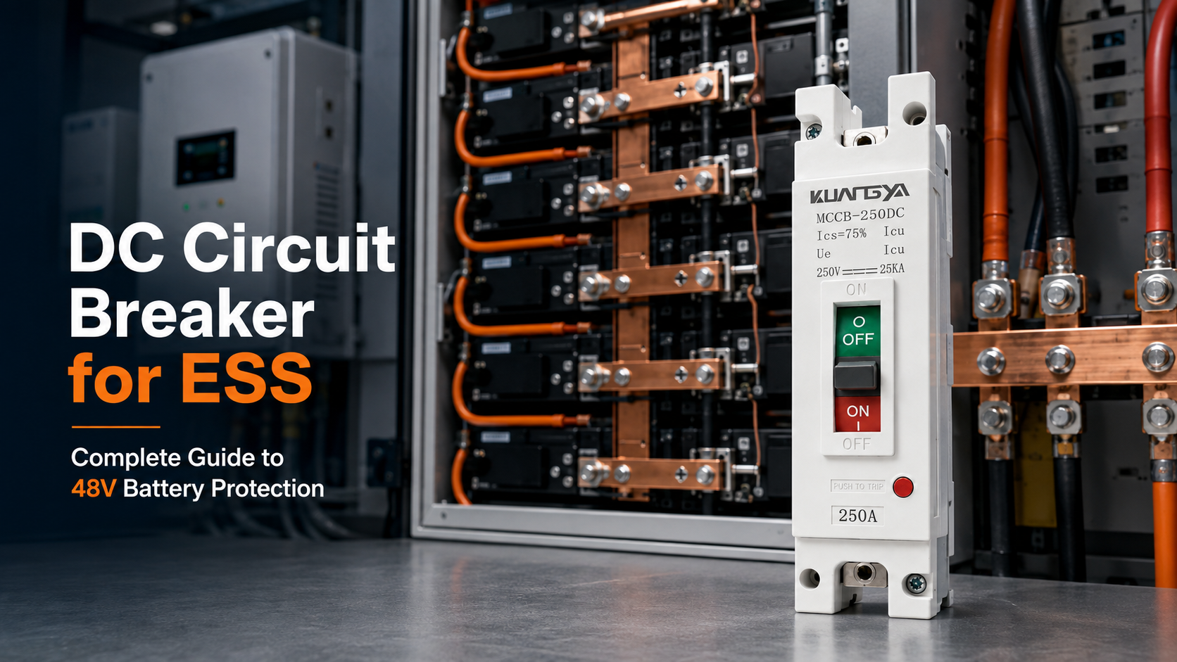
Un système de stockage d'énergie 48V est souvent décrit comme un système de batterie basse tension. Cependant, basse tension ne signifie pas faible risque électrique.
Lorsqu'un onduleur haute puissance fonctionne à partir d'un parc de batteries 48V, le courant côté batterie peut facilement dépasser 200A. En cas de court-circuit, le courant de défaut disponible peut être nettement plus élevé, en fonction de la chimie de la batterie, de la résistance interne, du nombre de modules de batterie en parallèle, de l'impédance des câbles et de la configuration du système.
Pour cette raison, la sélection d'un disjoncteur CC pour les applications ESS nécessite plus que la simple vérification de la tension nominale de la batterie et le choix du calibre de courant le plus proche.
Les ingénieurs et les intégrateurs système doivent également prendre en compte :
Ce guide explique comment un disjoncteur boîtier moulé (MCCB) CC est utilisé dans un système de stockage d'énergie 48V, comment calculer le courant côté batterie, comment comprendre Icu et Ics, et quand un MCCB CC 1P 250A peut être envisagé pour la protection de batterie ESS.
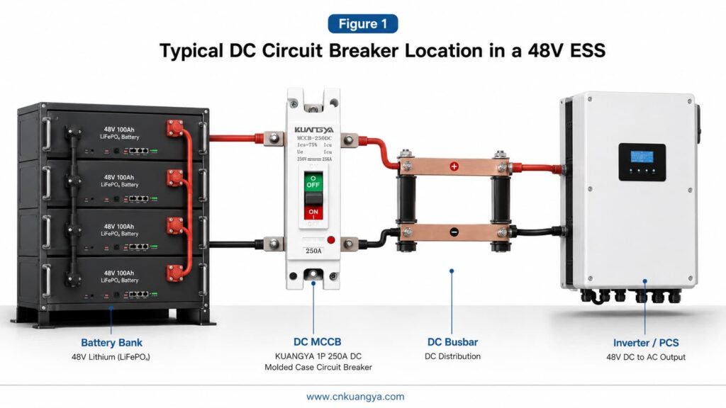
Un disjoncteur CC pour ESS est installé côté batterie d'un système de stockage d'énergie pour assurer une protection contre les surintensités et un moyen visible d'isolation électrique.
Pour un système de batterie 48V, le disjoncteur approprié ne doit pas être sélectionné uniquement sur la base de la tension nominale. Le calcul doit prendre en compte la tension de fonctionnement minimale de la batterie, le rendement de l'onduleur, la puissance continue maximale, les exigences de surcharge, la capacité des câbles et le courant de défaut disponible.
Un disjoncteur boîtier moulé (MCCB) CC 1P 250A peut convenir à certaines architectures de systèmes de stockage d'énergie (ESS) 48V, mais uniquement lorsque :
Un calibre de 250 A ne suffit pas à prouver qu'un disjoncteur est adapté à tous les systèmes de batteries 48 V.
Dans ce guide, vous apprendrez :
Un disjoncteur CC pour ESS est un dispositif de protection et de coupure installé dans la section courant continu d'un système de stockage d'énergie.
Pour une explication plus détaillée de la construction en boîtier moulé, des caractéristiques nominales CC, des déclencheurs et des exigences d'application, lisez notre guide complet Guide de sélection et normes pour disjoncteurs boîtier moulé (MCCB) CC.
Selon la conception du système, il peut être installé entre :
Ses fonctions principales incluent normalement :
Un disjoncteur à boîtier moulé, ou MCCB, est couramment utilisé lorsque le courant requis est supérieur à la plage normalement gérée par les petits disjoncteurs modulaires.
CEI 60947-2:2024 couvre les disjoncteurs avec des tensions nominales allant jusqu'à 1 000 V CA ou 1 500 V CC et stipule que les dispositifs concernés sont destinés à être installés et utilisés par des personnes instruites ou qualifiées. La norme s'applique aux disjoncteurs de différents calibres de courant et méthodes de construction.
Le système de stockage d'énergie (ESS) lui-même doit également être considéré comme un système complet. CEI 62933-5-1:2024 traite de l'identification des dangers, de l'évaluation des risques et de l'atténuation des risques pour les systèmes de stockage d'énergie électrique intégrés au réseau, tandis que IEC 62933-5-2:2025 fournit des exigences de sécurité supplémentaires au niveau du système pour les systèmes de stockage d'énergie électrochimique.
Un disjoncteur n'est donc qu'un élément d'une stratégie de protection complète pour les systèmes de stockage d'énergie (ESS).
Pour les projets de batteries à plus haute tension, consultez notre guide de protection et de conformité CC pour BESS 1500V pour en savoir plus sur la coordination des protections, la sélection des composants et les exigences de sécurité au niveau du système.
La raison principale est simple :
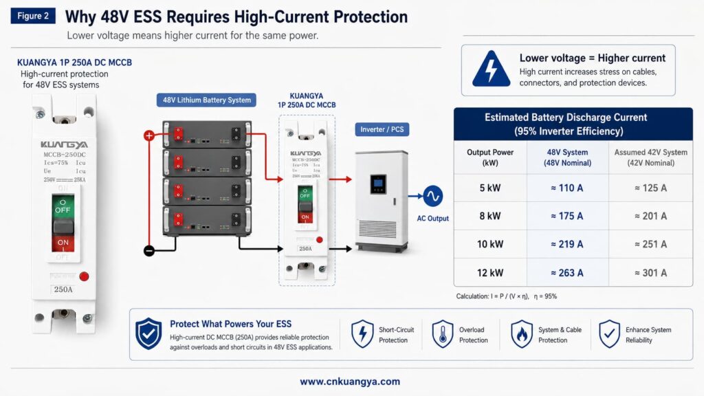
Pour une même puissance, une tension système plus faible nécessite un courant plus élevé.
La relation fondamentale est :
Puissance = Tension × CourantPar conséquent :
Courant = Puissance ÷ TensionUne charge de 10 kW fonctionnant à partir d'une source idéale de 48 V nécessiterait environ :
10 000 W ÷ 48 V = 208 ACependant, ce calcul simple ne prend pas en compte les pertes de l'onduleur ni la chute de tension de la batterie pendant la décharge.
Un calcul plus utile est :
PDC,in = PAC,out ÷ ηinvPar exemple, en supposant un rendement d'onduleur de 95 % :
10 000 W ÷ 48 V ÷ 0,95 = environ 219 AIf the battery voltage falls to 42V:
10,000W ÷ 42V ÷ 0.95 = approximately 251AThis example shows why a 250A circuit breaker cannot automatically be considered suitable for every 10kW, 48V battery system.
The actual maximum current may occur when:
The following table is based on 95% efficiency and is for preliminary comparison only.
| Inverter Power | Current at 48V | Current at 42V |
|---|---|---|
| 5kW | Approximately 110A | Approximately 125A |
| 8kW | Approximately 175A | Approximately 201A |
| 10kW | Approximately 219A | Approximately 251A |
| 12kW | Approximately 263A | Approximately 301A |
The minimum battery voltage must come from the battery manufacturer or system design. It should not be assumed from the words “48V battery.”
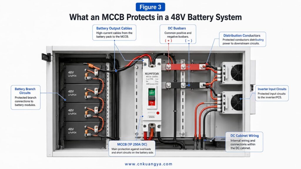
A battery-side MCCB mainly protects the electrical circuit connected to the battery.
Depending on the protection coordination and product characteristics, this may include:
The circuit breaker is normally selected to coordinate with the current-carrying capacity of the protected cable or busbar.
This means the breaker rating should not be increased simply because the inverter occasionally requires more current. If the conductor cannot safely carry that current, increasing the breaker rating may leave the conductor inadequately protected.
The breaker may also provide a visible and resettable means of isolation. However, whether it can be used as the required maintenance isolator depends on:
A circuit breaker does not directly monitor individual battery cells. Cell voltage, cell temperature and state-of-charge monitoring are normally handled by the battery management system.
To understand how circuit breakers, fuses, SPDs and other protective devices work together, read our guide to PV and ESS protection coordination.
A circuit breaker should be selected for the actual type of current in the circuit.
Alternating current passes through a natural current zero during every electrical cycle. This natural zero helps an AC switching device extinguish the electrical arc when the contacts open.
Direct current does not have the same natural current-zero crossing. The arc may therefore be more difficult to extinguish.
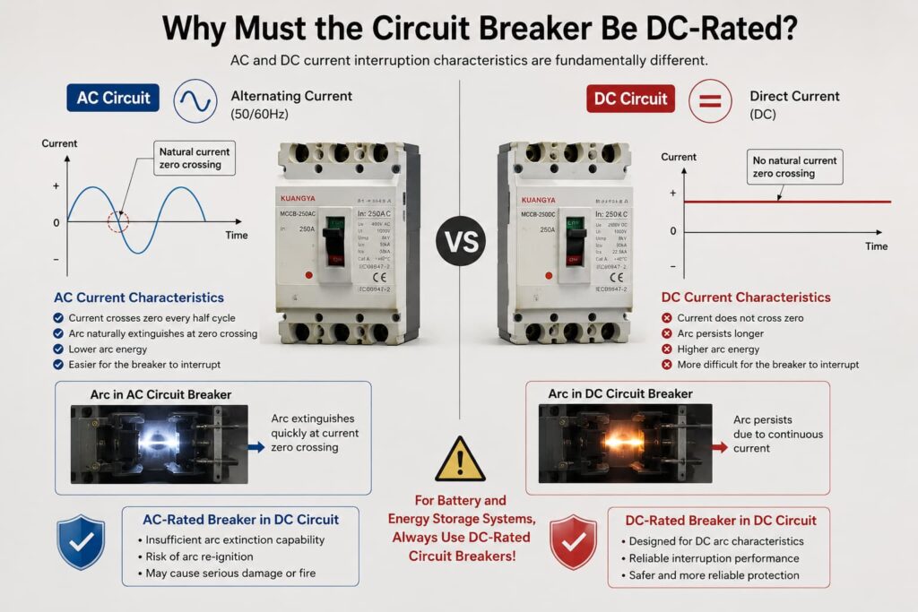
ABB’s technical guide for direct-current circuit-breaker applications explains how DC network configuration, pole connection, operational voltage and prospective fault current affect circuit-breaker selection.
A DC-rated MCCB may use features such as:
An AC voltage marking does not automatically establish a DC interrupting rating.
Before using any MCCB in an ESS, confirm:
UL’s MCCB application guidance also distinguishes specific DC markings and applications, including circuit breakers intended for battery power-supply systems. This reinforces the need to verify the exact DC rating shown on the device and in its certification documentation rather than assuming an AC-rated breaker is acceptable.
A BMS, fuse, contactor and MCCB perform different functions.
They should not automatically be treated as interchangeable devices.
| Dispositif | Fonction principale | Réarmable ? | Typical Role in ESS |
|---|---|---|---|
| BMS (Système de gestion de batterie) | Battery monitoring and control | Oui | Monitors cell voltage, temperature, current and battery status |
| Contacteur | Electrically controlled connection and disconnection | Oui | Connects or disconnects the battery under BMS or controller command |
| Fusible | Overcurrent and short-circuit interruption | Non | Provides one-time fault protection |
| MCCB | Overcurrent protection and manual switching | Oui | Protects conductors and provides resettable isolation |
| Isolateur | Manual circuit separation | Oui | Provides isolation but may not provide overcurrent protection |
Le U.S. Department of Energy’s Battery Energy Storage Systems Report describes the BMS as performing battery health monitoring and control, while identifying electrical disconnects, circuit breakers and switches as separate BESS protection components.
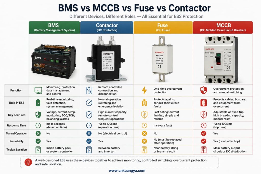
The BMS may monitor:
It may command a contactor to open when it detects an abnormal condition.
However, an electronic BMS can be affected by:
For this reason, the BMS should not automatically be treated as a replacement for correctly coordinated overcurrent protection.
A contactor provides electrically controlled switching.
It is suitable for frequent opening and closing under defined operating conditions. However, its short-circuit interruption capability may be limited unless it is specifically designed and tested for that function.
A contactor may work together with a fuse or circuit breaker.
A DC fuse provides one-time overcurrent protection.
A correctly selected fuse may offer:
After operating, it must be replaced.
For more information about fuse voltage ratings, current ratings and breaking capacity, read our guide on how to select fuses for electrical systems.
A DC MCCB may provide:
Whether an ESS needs both a fuse and an MCCB depends on the fault study, equipment ratings, selectivity requirements and system design.
For a detailed comparison of reset capability, operating speed, maintenance and typical applications, read DC circuit breaker vs DC fuse.
Correct current calculation begins with the battery side of the system, not the inverter’s AC output current.
Obtain:
The maximum battery voltage must remain within the MCCB’s verified DC voltage rating.
The minimum battery voltage is important because it may produce the highest operating current.
Use the maximum continuous inverter or PCS output power, not only the normal daily load.
Also check whether the manufacturer specifies:
Use:
I = P ÷ V ÷ ηOù ?
I = calculated DC currentP = maximum continuous powerV = battery voltage used for the calculationη = inverter efficiency expressed as a decimalFor a 10kW inverter, 42V minimum battery voltage and 95% efficiency:
I = 10,000 ÷ 42 ÷ 0.95
I = approximately 251A
In this example, a 250A breaker may already be too close to or below the expected maximum continuous current before temperature and installation derating are considered.
Do not assume the discharge current is always the highest current.
Some PCS and ESS applications may have different charge and discharge limits. Check both directions.
An inverter may have a short-time overload rating.
The designer must compare:
The breaker should not trip during permitted operating conditions, but it must still protect the circuit under abnormal conditions.
The rated current printed on an MCCB is only the starting point.
A complete selection should consider:
The breaker should be able to carry the maximum expected continuous current under the actual operating conditions.
The selected breaker should coordinate with the protected conductor.
Important conductor factors include:
The current-carrying capability and trip behavior of a thermal-magnetic MCCB may change with temperature.
A breaker installed in a hot battery cabinet cannot automatically be evaluated using open-air conditions.
Battery cabinets may contain:
The combined heat can affect the breaker and conductor capacity.
Confirm whether the breaker uses:
A 250A frame size does not always mean the device has the same trip settings as every other 250A breaker.
Some breakers have defined mounting orientations.
The manufacturer’s instructions should be followed for:
Rated current and breaking capacity are different parameters.
The rated current indicates the current the breaker is designed to carry under specified conditions.
Par exemple :
In = 250AThis does not mean the breaker can interrupt only 250A.
Icu represents the ultimate short-circuit breaking capacity under specified test conditions.
It indicates the maximum prospective short-circuit current the breaker can interrupt according to the applicable test sequence.
Ics represents the service short-circuit breaking capacity.
It is commonly expressed as a percentage of Icu, such as:
The exact marking depends on the product and test results.
The KUANGYA product image supplied for this project shows:
Ics = 75% IcuIf the verified Icu is 25kA under the stated DC test conditions, then:
Ics = 25kA × 75%
Ics = 18.75kA
However, this calculation is valid only when the Icu value, voltage, pole configuration and test conditions are correctly matched.
IEC 60947-2 provides the relevant framework for low-voltage circuit-breaker ratings and testing. Final product claims should be based on the corresponding test report, certificate and technical datasheet.
The DC breaking capacity must be higher than the prospective short-circuit current at the breaker’s installation point.
Do not select breaking capacity only from:
A battery bank may deliver a high short-circuit current because of its low internal resistance.
The actual fault current depends on:
When battery strings are connected in parallel, more than one string may contribute current to a fault.
This can increase the available fault current at:
The final breaker selection should therefore be supported by:
A 25kA marking should not be interpreted independently from its specified DC voltage and pole configuration.
The correct number of poles depends on the electrical architecture
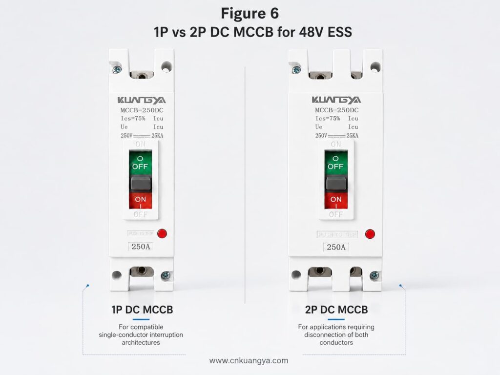
It should not be selected from voltage alone.
A 1P DC MCCB may be considered when:
A 2P breaker may be considered when:
Overcurrent protection and complete isolation are not always the same requirement.
A system may use:
The decision must be based on the complete wiring diagram, grounding method and applicable requirements.
Do not publish a statement that all 48V battery systems only require a 1P breaker.
ESS battery circuits may operate in two directions:
This means the selected protection device must be evaluated for the actual current direction.
Some DC circuit breakers are:
A product should not be described as bidirectional unless this is supported by its design and technical documentation.
For a battery ESS application, confirm:
This must be confirmed before finalizing the product page and technical datasheet.
A battery circuit breaker is normally installed so that the vulnerable conductor length between the battery source and the protection device is minimized, subject to the system design and applicable installation requirements.
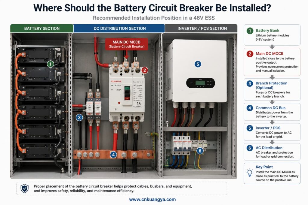
A simplified arrangement may be:
Battery Bank
     ↓
DC Fuse or DC MCCB
     ↓
DC Busbar or Distribution Cabinet
     ↓
Inverter or PCS
     ↓
AC Distribution System
Another arrangement may use separate protection for each battery string:
Battery String 1 → Branch Protection ┐
Battery String 2 → Branch Protection ├→ Common DC Bus → Main MCCB → PCS
Battery String 3 → Branch Protection ┘
The exact position depends on:
The breaker should remain accessible for operation, inspection and maintenance.
Installation work should be completed by qualified personnel using the manufacturer’s instructions, appropriate lockout procedures, verified isolation, suitable protective equipment and specified terminal torque. IEC 60947-2:2024 describes its covered circuit breakers as intended for installation and operation by instructed or skilled persons.
The KUANGYA MCCB-250DC is intended for high-current DC circuit protection in compatible battery and energy storage architectures.
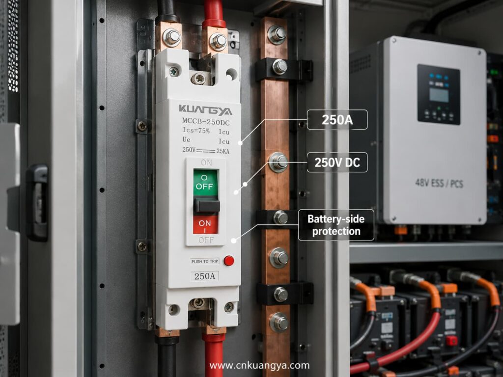
Based on the current product marking supplied for this article, the main information is:
| Product Parameter | Marked or Proposed Information |
|---|---|
| Type de produit | DC molded case circuit breaker |
| Modèle | MCCB-250DC |
| Nombre de pôles | 1P |
| Courant nominal | 250A |
| Marked DC Voltage | 250V DC |
| Marked Icu | 25kA |
| Marked Ics | 75% of Icu |
| Poignée de manœuvre | ON/OFF manual operation |
| Test Function | Push-to-trip button |
| Target Application | Compatible 48V ESS battery circuits |
The product’s 250V DC voltage marking is the component rating shown on the breaker. The application can still be described as a 48V ESS application because 48V refers to the nominal system in which it is used.
A suitable product description is:
The KUANGYA 1P 250A DC MCCB is designed for high-current battery-side protection in compatible 48V energy storage system architectures. It provides manual switching and overcurrent protection between the battery bank, DC distribution circuit and inverter or PCS, subject to verification of the continuous current, available fault current, conductor capacity, grounding arrangement and system requirements.
It may be considered when:
Potential applications include:
Application suitability must be confirmed for each project.
“48V” does not provide enough information.
The designer also needs minimum voltage, maximum charging voltage, current, fault level and grounding arrangement.
The AC output current is not the same as the DC battery input current.
Battery-side current must be calculated from power, battery voltage and efficiency.
The highest operating current may occur at the battery’s minimum voltage.
A 10kW inverter can draw more than 250A when battery voltage is low or efficiency losses are included.
They describe different capabilities.
An AC marking does not automatically establish safe DC interruption.
The BMS provides monitoring and control. Overcurrent protection and manual isolation are separate system functions.
Pole configuration must be based on the complete electrical design.
ESS systems normally charge and discharge. Breaker suitability must be checked for both operating directions.
High internal temperature may affect continuous current capability and trip behavior.
A complete selection also requires:
To recommend the correct DC MCCB for an ESS project, provide the following information.
Providing these details helps the manufacturer recommend a suitable model instead of selecting only from “48V” and “250A.”
Buyers can also request the latest KUANGYA product catalogue to review available models, technical parameters and OEM options.
Because power is the product of voltage and current. A high-power inverter operating from a low-voltage battery requires a high DC current.
A 10kW inverter can draw more than 200A from a 48V battery and may approach or exceed 250A as battery voltage decreases.
It may be suitable in some systems, but it cannot be confirmed from inverter power and nominal voltage alone.
At 48V and 95% efficiency, a 10kW inverter requires approximately 219A. At 42V, the calculated current rises to approximately 251A.
The final selection must consider minimum battery voltage, overload, cable capacity, ambient temperature and trip characteristics.
Only when the manufacturer provides a suitable DC rating and connection method for the exact product.
An AC rating alone is not sufficient.
Non.
The BMS monitors and controls the battery. A circuit breaker or fuse performs a separate overcurrent-protection function, while a contactor provides controlled switching.
These devices must be coordinated as part of the complete system.
The 250A value refers to the rated operating current.
The 25kA value refers to a stated short-circuit breaking capacity under defined voltage, pole and test conditions.
It means the service short-circuit breaking capacity is stated as 75% of the ultimate short-circuit breaking capacity.
If the verified Icu is 25kA, the corresponding Ics would be 18.75kA under the applicable test conditions.
It depends on:
A 1P product should not be used automatically in every 48V system.
Some DC MCCBs can, while others are polarized or require a defined LINE and LOAD connection.
Bidirectional operation must be confirmed in the product documentation.
It is normally installed on the battery output circuit, positioned according to the system protection design so that the unprotected conductor length is minimized.
The exact arrangement depends on battery strings, busbars, fuses, contactors and inverter connections.
Possibly.
A fuse and MCCB may provide different operating speeds, breaking capacities and coordination functions. Whether both are needed depends on the fault-current study and protection design.
It may provide manual disconnection when the product is rated and approved for the required switching and isolation function.
The overall system must still satisfy maintenance, lockout and disconnection requirements.
Non.
The 250V DC marking represents the breaker’s rated operational-voltage capability under specified conditions. A 48V system is below that voltage.
The other parameters still need to be checked.
At minimum, request:
Non.
Battery capacity in ampere-hours describes stored charge, not the complete operating or short-circuit current.
Breaker selection requires current, voltage, fault-current and conductor information.
Selecting a disjoncteur CC pour les applications ESS applications requires a complete review of the battery, inverter, conductors, fault level and system architecture.
For a 48V energy storage system, low voltage can result in very high operating current. A 10kW inverter may draw approximately 219A at 48V and more than 250A when the battery voltage falls to 42V, assuming 95% efficiency.
This means a 1P 250A DC MCCB should not be selected from the words “48V” and “250A” alone.
Before confirming the breaker, check:
For compatible single-pole 48V ESS architectures, the KUANGYA MCCB-250DC 1P 250A DC MCCB can provide a compact battery-side protection option, subject to final technical verification.
To request a model recommendation, datasheet or factory quotation, provide:
Contact KUANGYA for 48V ESS DC MCCB selection, OEM options and bulk-order support.
Site web : www.cnkuangya.com

