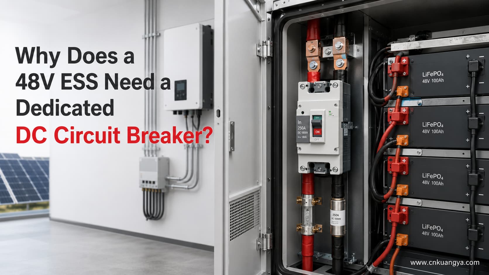
なぜ48V ESSには専用の直流(DC)サーキットブレーカーが必要なのか?

48Vエネルギー貯蔵システムは一般的に低電圧システムと呼ばれます。しかし、低電圧であることは電気的リスクが低いことを意味するわけではありません。.

48Vバッテリーバンクが高出力インバーターに電力を供給する場合、バッテリー側の電流は容易に100A、200A、あるいは250Aを超えることがあります。その電流は、バッテリーケーブル、バスバー、端子、コンタクタ、ヒューズ、サーキットブレーカー、およびインバーター入力導体を通過します。.

過負荷、短絡、接続の緩み、絶縁不良、またはバッテリー分岐の故障が発生した場合、その結果生じる熱や故障エネルギーが導体や機器を損傷させる可能性があります。.

これが、適切に選定された 48V DCサーキットブレーカーが バッテリー側保護システムの一部として設置される理由です。.

ただし、ブレーカーの選定はインバーターの電力のみに基づいて行ってはなりません。設計全体において、以下の要素を考慮する必要があります。

  • バッテリーの動作電圧範囲
  • インバーターの効率
  • 最大連続充放電電流
  • 一時的なピーク電流
  • バッテリーおよびBMSの制限
  • ケーブルおよびバスバーの許容電流
  • 利用可能な短絡電流
  • ブレーカーのDC定格電圧
  • 直流遮断容量
  • トリップ特性
  • 極構成
  • 接地方式
  • 電流方向
  • 周囲温度によるディレーティング

ESS用ブレーカーの電圧、電流、遮断容量、極構成、および協調に関する詳細な説明については、以下をご覧ください。 ESS向け直流遮断器選定ガイド(完全版).

クイックアンサー

48VのESSには専用の直流過電流保護システムが必要です。低電圧バッテリーであっても非常に大きな電流が流れる可能性があるためです。.

適切に選択された 48V DCサーキットブレーカーが 提供可能:

  • バッテリーケーブルの過負荷保護
  • 検証済みの遮断容量内での短絡保護
  • バッテリー側での手動遮断
  • 特定の故障発生後の復帰可能な動作
  • BMS、コンタクタ、ヒューズ、インバータ、およびバッテリー分岐回路との協調

BMSは通常、バッテリー電圧、セル電圧、電流、温度、および動作制限を監視します。システム構成に応じて、インバータ、充電器、コンタクタ、または外部スイッチングデバイスに対し、電流を停止するよう指令を出す場合があります。.

その機能をもって、BMSが専用の過電流保護装置の代替品となるわけではありません。.

BMS、コンタクタ、ヒューズ、およびDC MCCBは、それぞれ異なる機能を果たします。.

BMS、コンタクタ、ヒューズ、DCブレーカー:その違いとは?

装置主機能バッテリーセルを自動監視しますか?故障電流を遮断できますか?リセット可能ですか?手動絶縁機能
BMS(バッテリーマネジメントシステム)バッテリーの動作状態を監視および制御するはい通常は他の開閉装置を介して行うはい通常はいいえ
電磁接触器(コンタクタ)バッテリーの電気的な接続または遮断を行ういいえ指定された直流遮断定格の範囲内でのみ可能はい通常、主手動アイソレーターとしては使用されない
ヒューズ一回限りの過電流および短絡保護を提供するいいえはい、直流定格の範囲内であれば可能いいえいいえ
DC MCCB過負荷および短絡保護を提供するいいえはい、検証済みの直流遮断容量の範囲内であれば可能ですはい開閉または絶縁の定格がある場合は可能です
Switch-disconnectorProvides manual isolationいいえNot necessarily suitable for fault interruptionはいはい
BMS contactor fuse and DC MCCB functions in a 48V ESS
The BMS, contactor, fuse and DC MCCB perform different monitoring, switching and protection functions in an ESS.

Modern BMS documentation shows that the BMS may monitor cell voltage, current, and temperature and then send commands to loads, chargers, or contactors. One practical example is the Victron VE.Bus BMS NG manual, which describes cell-level monitoring and the enabling or disabling of charging and discharging according to battery conditions. Some systems use a contactor as a secondary safety device if normal BMS control functions fail. This confirms that monitoring, control, switching, and overcurrent protection are separate functions that must be coordinated.

The correct conclusion is:

These devices perform different functions and should be coordinated as part of the complete ESS protection design.

For a focused comparison of operating speed, reset capability, maintenance, and typical applications, read our DC circuit breaker vs DC fuse guide.

Why Low Voltage Does Not Mean Low Current

The basic relationship between power, voltage, and current is:

P = V × I

Therefore:

I = P ÷ V

For an inverter, efficiency must also be considered. A more useful battery-side current estimate is:

I₍DC₎ = P₍AC output₎ ÷ (V₍battery₎ × η)

どこでだ:

  • I₍DC₎ is the estimated battery current in amperes
  • P₍AC output₎ is the inverter’s real AC output power in watts
  • V₍battery₎ is the actual battery voltage under load
  • η is inverter efficiency expressed as a decimal

For example, 95% efficiency is entered as 0.95.

This formula estimates steady-state battery current. It does not include every possible variable, such as inverter standby consumption, control-system consumption, cable losses, temporary overload, startup surge, current ripple, or manufacturer-specific operating limits.

Calculated Battery Current for 5kW and 10kW Loads

The following calculations assume 95% inverter efficiency.

AC output powerBattery voltage under loadAssumed efficiency計算Estimated battery current
5,000W48V95%5,000 ÷ (48 × 0.95)109.6A
5,000W44V95%5,000 ÷ (44 × 0.95)119.6A
5,000W42V95%5,000 ÷ (42 × 0.95)125.3A
10,000W48V95%10,000 ÷ (48 × 0.95)219.3A
10,000W44V95%10,000 ÷ (44 × 0.95)239.2A
10,000W42V95%10,000 ÷ (42 × 0.95)250.6A
48V ESS battery current comparison for 5kW and 10kW inverter loads
At 48V and 95% inverter efficiency, a 5kW load requires about 110A while a 10kW load requires about 219A.

These calculations show why the nominal “48V” label is not enough.

A 10kW inverter drawing from a battery at 48V may require approximately 219A under the stated assumptions. If the battery voltage falls to 42V, the calculated current rises to approximately 251A.

This is before adding design allowances for operating conditions, auxiliary consumption, cable losses, temporary overload, or manufacturer-specific requirements.

Therefore, a 250A battery breaker for an inverter is not automatically suitable for every 10kW, 48V system.

Why Battery Voltage Falls Under Load

A battery described as “48V” does not remain at exactly 48.0V throughout charging and discharging.

The actual operating voltage depends on:

  • Battery chemistry
  • Number of cells in series
  • State of charge
  • Charge or discharge current
  • Cell temperature
  • Internal resistance
  • Cable voltage drop
  • BMS limits
  • Inverter low-voltage settings

A published 51.2V LiFePO4 battery example has a nominal voltage of 51.2V, a recommended charging voltage between 56V and 56.8V, and an end-of-discharge voltage of 44.8V. This demonstrates why both maximum charging voltage and lower discharge voltage must be considered when selecting a breaker.

The breaker voltage rating must be higher than the maximum battery-system voltage that can appear across it.

The current calculation should also be checked at the lowest permitted operating voltage, because lower battery voltage produces higher current for the same power output.

Real Engineering Case 1: A 48V 5kVA Inverter/Charger

Consider a published 48V inverter/charger with the following manufacturer data:

パラメータPublished value
Model class48V / 5,000VA
Continuous real output at 25°C4,000W
Battery input voltage range38–66V
Maximum efficiency96%
Peak power9,000W
Recommended DC fuse200A
Recommended cable for 0–5m70mm²
Recommended cable for 5–10m120mm²
48V 5kVA inverter system with 200A DC fuse and battery cables
A published 48V 5kVA inverter example recommends a 200A DC fuse even though the calculated continuous battery current is below 100A.

These values are taken from the manufacturer’s MultiPlus-II and Quattro-II installation manual rather than estimated from the product name.

At 48V and 96% efficiency:

I = 4,000 ÷ (48 × 0.96)

I ≈ 86.8A

At 42V and 96% efficiency:

I = 4,000 ÷ (42 × 0.96)

I ≈ 99.2A

A buyer might see the calculated 87–99A current and immediately choose a 100A or 125A breaker.

However, the manufacturer recommends a 200A DC fuse for this particular inverter/charger.

Why is the recommendation higher than the basic continuous-current calculation?

Because the final protection requirement may need to account for:

  • Peak inverter power
  • Temporary overload
  • Inrush current
  • Fuse time-current characteristics
  • Battery cable configuration
  • Nuisance-trip prevention
  • Internal inverter design
  • Manufacturer testing
  • Thermal operating conditions

This case demonstrates an important rule:

The power formula is a starting point, not the final breaker size.

The inverter manufacturer’s approved installation instructions, battery limits, cable capacity, and protective-device characteristics must all be reviewed.

It would also be incorrect to copy the manufacturer’s 200A fuse recommendation and automatically replace it with a 200A MCCB. A fuse and an MCCB may have different operating curves, short-circuit performance, let-through energy, and interruption characteristics.

Real Engineering Case 2: A 48V 10kVA Inverter/Charger

Now consider a larger published inverter/charger.

パラメータPublished value
Model class48V / 10,000VA
Continuous real output at 25°C8,000W
Continuous real output at 40°C7,000W
Continuous real output at 65°C6,000W
Battery input voltage range38–66V
Maximum efficiency95%
Peak power18,000W
Recommended DC fuse400A
Recommended cable for 0–5m2 × 50mm² per polarity
Recommended cable for 5–10m2 × 70mm² per polarity
48V 10kVA inverter system with 400A DC fuse and parallel battery cables
A published 48V 10kVA inverter example uses a 400A DC fuse and parallel battery cables, showing why power calculations alone cannot determine protection size.

The same manufacturer manual publishes 8,000W as the continuous real output at 25°C, although the model is identified as 10,000VA. although the model is identified as 10,000VA. It also recommends a 400A DC fuse and two parallel 50mm² conductors per positive and negative connection for cable runs up to 5m.

At 48V and 95% efficiency:

I = 8,000 ÷ (48 × 0.95)

I ≈ 175.4A

At 42V and 95% efficiency:

I = 8,000 ÷ (42 × 0.95)

I ≈ 200.5A

A simple calculation might suggest that a 250A DC MCCB should be enough.

However, the manufacturer recommends a 400A fuse for this particular unit.

That does not mean every similar 48V inverter requires a 400A protective device. It means that the protection selection for this specific inverter must follow its tested and published installation requirements.

This real example also shows why an engineer must distinguish between:

  • VA rating
  • Continuous real power in watts
  • Peak power
  • Calculated continuous battery current
  • Recommended protective-device rating
  • Protective-device trip curve
  • Cable configuration

A product marked “10kVA” is not necessarily delivering 10kW of continuous real power under every condition.

Real Engineering Case 3: Two Parallel 51.2V LiFePO4 Batteries

Consider two identical 51.2V, 100Ah LiFePO4 batteries connected in parallel.

The published specification for each battery includes:

Parameter per batteryPublished value
Nominal voltage51.2V
Nominal capacity100Ah
Nominal energy5.12kWh
Maximum continuous discharge current100A
Maximum pulse discharge current200A for 10 seconds
End-of-discharge voltage44.8V
Charging voltage56–56.8V

The battery manufacturer also states that fuse selection should not exceed the lowest current rating among the battery, cable, and system limits.

With two identical batteries in parallel, the theoretical combined values become:

Combined parameter計算結果
Nominal capacity100Ah × 2200Ah
Nominal energy5.12kWh × 210.24kWh
Maximum continuous discharge current100A × 2200A
Maximum 10-second pulse current200A × 2400A
Two parallel 51.2V LiFePO4 batteries with branch fuses and main DC MCCB
Parallel batteries may require individual branch protection because healthy branches can feed current into a faulted battery branch.

These totals assume that the two branches share current correctly and that the batteries, cables, terminals, fuses, and busbars are installed according to the manufacturer’s requirements.

This case creates an important protection question:

Can one 250A main breaker protect the entire battery system?

Possibly—but it cannot be confirmed from the total current alone.

A 250A main breaker might allow more than 100A to flow continuously through one battery branch if current sharing becomes unequal. Therefore, each battery branch may still need dedicated branch protection coordinated with:

  • The 100A continuous battery limit
  • Branch cable capacity
  • Battery terminal limits
  • Manufacturer instructions
  • Expected current sharing
  • Prospective reverse current from the other branch

A main 48V DCサーキットブレーカーが does not automatically replace battery-branch fuses or breakers.

This is especially important in parallel battery systems because healthy battery branches may feed current into a faulted branch.

What Can Go Wrong on the Battery Side?

Battery Cable Overload

Battery cables may carry high current for long periods.

A cable can overheat if it is:

  • Undersized
  • Installed in a hot cabinet
  • Bundled with other cables
  • Installed in closed conduit
  • Terminated incorrectly
  • Connected through an undersized lug
  • Longer than expected
  • Subjected to excessive voltage drop

The breaker must protect the lowest-rated component in the current path.

Busbar or Terminal Short Circuit

A dropped tool, loose conductor, failed insulator, damaged lug, or installation error can create a short circuit across a battery busbar.

Lithium batteries may supply substantial fault current. However, the prospective short-circuit current cannot be determined accurately from battery Ah capacity alone.

The calculation may require:

  • Battery internal resistance
  • Number of parallel batteries
  • Cable impedance
  • Busbar impedance
  • Connection resistance
  • BMS behavior
  • Contactor behavior
  • Fault location
  • Battery manufacturer fault-current data

The breaker’s verified DC breaking capacity must be equal to or greater than the prospective short-circuit current at the breaker installation point.

Inverter DC Input Fault

A fault may occur in the inverter input terminals, capacitors, internal conductors, or power electronics.

The BMS may detect abnormal current and command disconnection, but the result depends on sensors, software, communications, control power, switching equipment, and the nature of the fault.

Independent overcurrent protection provides another protection layer for the conductors between the battery and inverter.

Loose Connection and Local Heating

The heating produced by electrical resistance is:

P = I²R

どこでだ:

  • P is heat loss in watts
  • I is current in amperes
  • R is connection resistance in ohms

Suppose a loose terminal develops a resistance of only 0.001Ω.

At 100A:

P = 100² × 0.001 = 10W

At 200A:

P = 200² × 0.001 = 40W

At 250A:

P = 250² × 0.001 = 62.5W

This heat is concentrated at a small terminal or connection point.

The example shows why a connection that appears to have very low resistance can still generate significant heat in a high-current 48V system.

A circuit breaker may not detect every high-resistance connection. Correct torque, suitable terminals, proper crimping, thermal inspection, and maintenance are still required.

Reverse Current Between Parallel Battery Branches

If one parallel battery branch develops a short circuit, other battery branches may feed current into it.

This means that a single main breaker may not protect each branch conductor.

Branch fuses or breakers may be required close to each battery positive terminal, depending on the approved system design.

Contactor Fails to Open

A BMS-controlled contactor is an important switching device, but it should not automatically be treated as the only fault-clearing device.

The contactor may depend on:

  • BMS logic
  • 制御電源
  • Coil operation
  • コミュニケーション
  • Mechanical movement
  • Contact condition

Published BMS designs may use a main contactor as a secondary safety system after normal charge and discharge control functions. This supports the principle of using coordinated protection layers rather than relying on one device.

No Manual Isolation

Technicians need a clear method to isolate the battery before installation, maintenance, inspection, or component replacement.

A DC MCCB may provide manual switching and overcurrent protection, but only if the selected breaker is approved for the intended switching or isolation function.

If a fuse is used as the main overcurrent device, a separate DC switch-disconnector may also be required.

Why the Breaker Must Be DC-Rated

An AC breaker should not be assumed suitable for battery use merely because the battery voltage is only 48V.

AC and DC circuit breaker arc interruption comparison
AC current naturally crosses zero, while a DC breaker requires a dedicated arc-control system to interrupt continuous current safely.

For a broader explanation of arc interruption, voltage ratings, and application differences, read our guide to AC vs DC circuit protection.

AC Has Natural Current Zero Crossings

Alternating current passes through zero during every half-cycle.

This natural zero crossing helps extinguish the electrical arc that forms when breaker contacts open.

DC Does Not Have a Natural Zero Crossing

Direct current does not naturally pass through zero during normal steady-state operation.

The breaker must create sufficient arc voltage and arc resistance to force the DC fault current to zero.

ABB’s technical guide to circuit breakers for direct current applications provides further guidance on DC interruption, earthing arrangements, pole connections, and short-circuit calculations.

ABB’s technical guidance explains that interrupting DC current is more difficult because there is no natural current zero. It also explains that multiple breaker contacts or poles may need to be connected in series for higher DC voltage and breaking performance.

IEC 60947-2:2024 applies to low-voltage circuit breakers with rated voltages up to 1,000V AC or 1,500V DC. However, this does not mean every IEC 60947-2 breaker is suitable for every DC voltage or battery application. The manufacturer’s exact DC ratings and connection diagrams must still be verified.

What Must Be Checked on a DC Breaker?

Breaker parameterなぜそれが重要なのか
Rated DC operational voltageMust exceed the maximum battery-system voltage
定格電流Must coordinate with the load, battery, cable, and busbar
直流遮断容量Must exceed the prospective fault current
Trip curve or trip settingsMust carry normal load and peaks without losing protection
ポール数May affect voltage rating and isolation arrangement
Pole connection diagramSome DC ratings require poles connected in series
極性Some DC breakers are polarity-sensitive
Line and load directionSome products require a specified current direction
Bidirectional ratingRequired when charge and discharge current flow through the same path
Isolation ratingRequired when the breaker is used as an isolating device
Ambient deratingHigh cabinet temperature may reduce usable continuous current
Terminal limitsTerminals must accept the required conductor size and current

Some DC breakers use permanent magnets in their arc chambers. For these designs, polarity and current direction can affect arc movement and interruption performance. Manufacturer documentation must therefore be followed exactly.

Polarity, LINE and LOAD orientation, and bidirectional current are also covered in our guide to common DC protection wiring mistakes.

What Does a 48V DC Circuit Breaker Protect?

A battery-side breaker primarily protects the electrical circuit and its conductors.

Depending on its location, it may protect:

  • Main battery output cables
  • Battery branch conductors
  • DCバスバー
  • Inverter input conductors
  • PCS input wiring
  • DC cabinet wiring
  • Distribution cables
  • Conductors supplying DC loads

The breaker does not directly monitor individual cell voltage, cell temperature, state of charge, or cell balancing.

Those remain BMS and battery-system functions.

The correct protection concept is therefore:

The BMS protects battery operating conditions, while the DC overcurrent device protects the defined circuit and conductors within its ratings.

When Can a 250A DC MCCB Be Considered?

A 250A DC MCCB may be considered for some 48V ESS applications, but the current marked on the breaker is only one part of the selection.

For a broader explanation of DC MCCB construction, trip units, breaking capacity, and applicable standards, see our DC MCCB selection and standards guide.

Selection conditionWhat must be confirmedなぜそれが重要なのか
Battery maximum voltageBelow the breaker’s DC voltage ratingA nominal 48V battery may charge above 56V
Maximum continuous discharge currentCompatible with the breaker trip curvePrevents nuisance tripping and conductor overload
Maximum charging currentIncluded in the analysisESS current may flow in both directions
Lowest battery voltageUsed in current calculationCurrent rises when voltage falls
一時的なピーク電流Duration and magnitude are knownThe breaker must tolerate legitimate peaks
ケーブル容量Greater than or coordinated with breaker protectionThe breaker must protect the cable
Busbar and terminal capacitySuitable for continuous currentPrevents localized overheating
Available fault currentBelow verified DC breaking capacityEnsures safe fault interruption
BMS and contactor limitsCompatible with breaker and system currentPrevents one device from being overloaded
極構成Suitable for grounding and isolation designDetermines which conductors are disconnected
電流方向Breaker approved for bidirectional operation when requiredESS charging reverses normal current direction
周囲温度Manufacturer derating checkedHot cabinets affect trip behavior
Manufacturer instructionsInverter and battery requirements followedGeneric calculations do not replace approved manuals

250A DC MCCB Decision Examples

System conditionIs a 250A breaker automatically suitable?Reason
5kW output, 48V battery, 95% efficiencyいいえCalculated current is about 110A, but cable, surge, trip curve, fault current, and manufacturer requirements remain unknown
10kW output, 48V battery, 95% efficiencyいいえCalculated current is about 219A, leaving limited margin before considering operating conditions
10kW output, 42V battery, 95% efficiencyUsually not for continuous full outputCalculated current is approximately 251A before additional losses
Two 51.2V/100Ah batteries in parallelいいえCombined continuous current may be 200A, but each 100A battery branch may still require separate protection
Inverter manufacturer specifies a 400A fuseいいえA 250A MCCB cannot automatically replace the specified fuse
Cable is rated below 250A after deratingいいえThe breaker may not protect the cable adequately
Prospective fault current exceeds breaker DC breaking capacityいいえThe breaker may be unable to interrupt the fault safely
Breaker is AC-rated onlyいいえAC ratings do not automatically establish DC interruption performance
DC voltage, current, trip curve, cable, fault level, poles, temperature, and manufacturer requirements are verifiedPossiblyFinal approval still requires system-level engineering validation

If the system voltage, continuous current, cable capacity, pole arrangement, fault level, and current direction have been confirmed, review the KUANGYA MCCB-250DC product specifications before requesting a project quotation.

KUANGYA 1P 250A 250V DC MCCB for 48V ESS applications
The KUANGYA MCCB-250DC is a 1P 250A 250V DC breaker, but final selection must be verified against system current, fault level, cables and wiring architecture.

Is a 250A Breaker Suitable for a 10kW Inverter?

The answer depends on what “10kW inverter” means and how the system operates.

At 48V and 95% efficiency:

10,000 ÷ (48 × 0.95) ≈ 219A

At 44V:

10,000 ÷ (44 × 0.95) ≈ 239A

At 42V:

10,000 ÷ (42 × 0.95) ≈ 251A

Therefore, a 250A breaker may already be at or below the calculated full-load current when battery voltage falls.

The design must then consider:

  • Whether 10kW is continuous real output or only a model name
  • Minimum operating battery voltage
  • Inverter efficiency at that load
  • Temporary overload
  • Starting current
  • Breaker trip curve
  • Cabinet temperature
  • Cable derating
  • Manufacturer-specified fuse or breaker
  • Battery maximum discharge current

The correct answer cannot be obtained from “10kW” and “48V” alone.

1P or 2P for a 48V ESS?

There is no universal rule stating that every 48V ESS must use only a 1P or only a 2P breaker.

System condition1P may be considered2P may be considered
One conductor is intentionally groundedYes, subject to approved design時々
Floating or ungrounded DC systemUsually not enough for full isolationOften required
Both conductors must be isolatedいいえはい
Insulation monitoring is usedDepends on architectureCommonly considered
Manufacturer requires positive-only protectionPossibleFollow manufacturer diagram
Manufacturer requires all-pole disconnectionいいえはい
Single-pole breaker has sufficient DC ratingPossibleNot automatically required
Required DC rating needs two poles in seriesいいえYes, using the approved wiring diagram
The correct 1P or 2P arrangement depends on grounding, isolation requirements, equipment instructions and the breaker’s verified DC connection method.

When a 1P Breaker May Be Used

A 1P 48V DCサーキットブレーカーが may be used when:

  • The system architecture has been confirmed
  • Only one conductor is intended to be protected and disconnected
  • The grounding arrangement permits single-pole disconnection
  • The single pole has sufficient DC voltage rating
  • The single pole has sufficient breaking capacity
  • The inverter and battery manufacturers permit the arrangement
  • Manual-isolation requirements are satisfied

When a 2P Breaker May Be Used

A 2P breaker may be required when:

  • Both positive and negative conductors must be disconnected
  • The system is floating or ungrounded
  • All-pole isolation is required
  • The breaker needs two poles in series to achieve its DC rating
  • The inverter manufacturer requires two-pole disconnection
  • The system uses insulation monitoring
  • Either conductor may create a fault path to ground

Do not assume that two poles always mean one pole in the positive conductor and one in the negative conductor.

Some DC breaker ratings require poles to be connected in series in a specific arrangement. Always follow the manufacturer’s wiring diagram.

Common Misunderstandings

“48V Is Safe, So No Breaker Is Needed”

A lower system voltage does not eliminate the risk of high current.

High battery current can cause:

  • ケーブルの過熱
  • 溶けた断熱材
  • Damaged terminals
  • Busbar failure
  • Electrical arcing
  • 機器の損傷
  • Fire

“The Battery Has a BMS, So It Does Not Need a Breaker”

The BMS monitors battery conditions and controls other equipment.

The breaker or fuse protects the defined circuit against overcurrent and short-circuit conditions within its rating.

They perform different functions.

“Any AC Breaker Can Be Used at 48V DC”

An AC breaker may only be used on DC when the manufacturer provides an approved DC voltage, breaking capacity, pole arrangement, and connection diagram.

“A 250A Breaker Fits Every 10kW Inverter”

The current depends on the actual battery voltage, inverter efficiency, continuous real power, overload capability, and operating temperature.

A generic 10kW calculation at 42V and 95% efficiency already produces approximately 251A.

“Only Breaker Rated Current Matters”

A 250A label does not confirm:

  • DC voltage suitability
  • 破断能力
  • Trip behavior
  • 極性
  • Bidirectional operation
  • 極構成
  • Temperature performance
  • Isolation capability

“Battery Ah Determines Breaker Size”

Battery capacity in ampere-hours indicates stored charge.

It does not directly define:

  • Maximum continuous discharge current
  • Maximum charge current
  • Short-circuit current
  • BMS limit
  • ケーブル容量
  • Correct breaker size

“One Main Breaker Protects Every Parallel Battery”

A main breaker may protect the combined output cable but may not protect each individual battery branch.

Parallel branches may require separate protection near each battery.

“Charging Current Does Not Matter”

An ESS can carry current in both discharge and charge directions.

The breaker and protection system must be suitable for the maximum current and fault conditions in both operating modes.

Buyer’s Checklist for a 48V DC Circuit Breaker

A buyer should provide the following information before requesting a quotation.

Required informationWhy it is needed
Battery chemistryLiFePO4Determines voltage range and battery limits
Nominal battery voltage48V or 51.2VBasic system classification
Maximum charging voltage56.8VDetermines minimum breaker DC voltage rating
Minimum operating voltage44.8VUsed for maximum current estimation
Battery capacity200AhHelps describe the bank but does not determine breaker size alone
Number of batteries2 in parallelIdentifies branch-protection requirements
Maximum continuous discharge current200A totalUsed for current coordination
Maximum charge current150AConfirms reverse current requirements
Peak current350A for 5 secondsUsed to check trip characteristics
Inverter or PCS modelManufacturer and exact modelAllows manual verification
Continuous real output8,000WUsed for battery-current calculation
インバーターの効率95%Improves current calculation
Required poles1P or 2PDepends on system architecture
接地方式Floating or negative groundedAffects pole selection
Cable cross-section2 × 50mm²Required for conductor protection
ケーブル長3m one wayAffects voltage drop and cable sizing
Busbar rating300AMust coordinate with the breaker
Available fault currentEngineering calculation or manufacturer dataDetermines breaking capacity
動作温度Up to 50°CRequired for breaker derating
電流方向BidirectionalImportant for charging and discharging
Required standardIEC 60947-2 or market-specific requirementSupports compliance review
数量100 piecesRequired for commercial quotation
DestinationCountry and portRequired for shipping and certification review

よくあるご質問

Does a 48V lithium battery need a circuit breaker?

A 48V lithium battery system normally requires a coordinated overcurrent protection and disconnection design.

The final solution may use:

  • A DC circuit breaker
  • A fuse and switch-disconnector
  • Battery-branch fuses
  • A main MCCB
  • A BMS-controlled contactor
  • A coordinated combination of these devices

The exact arrangement depends on the battery, inverter, cables, fault current, and applicable installation requirements.

Does the BMS replace the breaker?

そうだ。.

The BMS primarily monitors and controls battery operating conditions. The circuit breaker or fuse protects a defined circuit against overcurrent and short-circuit conditions within its verified ratings.

Can an AC breaker be used for a 48V battery?

Only when the manufacturer explicitly provides a suitable DC rating and approved connection method.

An AC marking alone is not enough.

What size breaker is needed for a 48V inverter?

Start by calculating:

I₍DC₎ = P₍AC output₎ ÷ (V₍battery minimum₎ × η)

Then verify:

  • Manufacturer instructions
  • Continuous and peak current
  • Battery limits
  • ケーブル容量
  • Breaker trip curve
  • 直流遮断容量
  • Ambient derating
  • 極構成
  • 電流方向

Is a 250A breaker suitable for a 10kW inverter?

Not automatically.

At 48V and 95% efficiency, the estimated current is approximately 219A.

At 42V, it rises to approximately 251A.

A 250A breaker may therefore be unsuitable for continuous full-power operation at lower battery voltage.

Should the breaker be installed on the positive or negative cable?

This depends on the grounding arrangement and equipment manufacturer’s instructions.

Many battery systems place overcurrent protection in the positive conductor, but this must not be generalized to every grounded, floating, or monitored DC system.

Should a 48V ESS use a 1P or 2P breaker?

A 1P breaker may be suitable for an approved single-conductor disconnection architecture.

A 2P breaker may be required when both positive and negative conductors must be disconnected or when two poles are needed to achieve the breaker’s verified DC rating.

Is a fuse still needed when an MCCB is installed?

Sometimes.

A fuse may provide higher short-circuit breaking capacity, faster fault interruption, branch protection, or backup protection.

Whether both devices are required depends on the coordination study and system design.

Can breaker size be selected from battery Ah capacity?

そうだ。.

Battery Ah capacity does not directly specify the maximum continuous current, short-circuit current, cable size, or protective-device rating.

Does a larger breaker provide better protection?

そうだ。.

An oversized breaker may fail to protect the cable, battery branch, terminal, or busbar adequately.

The breaker must be coordinated with the lowest-rated protected component.

Final Selection Principle

A 48V ESS is a low-voltage but potentially very high-current electrical system.

The correct protection question is not simply:

“Is 48V dangerous?”

The more useful questions are:

  • How much continuous current can flow?
  • What happens at minimum battery voltage?
  • What temporary peak current is expected?
  • What is the battery’s maximum discharge current?
  • What current can the cable and busbar safely carry?
  • What is the prospective short-circuit current?
  • Can the breaker safely interrupt that fault on DC?
  • Does the BMS control a contactor or only communicate with the inverter?
  • Is branch protection required?
  • Does the system need 1P or 2P disconnection?
  • Is current bidirectional?
  • What does the inverter manufacturer require?

A dedicated 48V DCサーキットブレーカーが can provide valuable overload protection, short-circuit interruption, manual operation, and resettable protection.

However, the breaker is only one part of the complete system.

The safest design coordinates the battery, BMS, contactor, fuse, MCCB, cable, busbar, inverter, grounding arrangement, and fault-current level.

Before selecting a 250A or any other breaker rating, provide the complete system parameters to the breaker manufacturer or qualified system designer.

The next step is not to guess the breaker size from inverter power. It is to calculate and verify the complete battery-side protection design.

チンクアンヤ
チンクアンヤ
記事本文: 70