Zona industrial de WengYang Yueqing Wenzhou 325000
Horas de trabajo
De lunes a viernes: de 7.00 a 19.00 horas
Fin de semana: 10.00 A 17.00 HORAS
Zona industrial de WengYang Yueqing Wenzhou 325000
Horas de trabajo
De lunes a viernes: de 7.00 a 19.00 horas
Fin de semana: 10.00 A 17.00 HORAS
It was a Tuesday morning in July when the maintenance team at a 500kW commercial solar installation in Arizona received the call they dreaded. A severe thunderstorm had passed through overnight, and the inverters were offline. When the technicians arrived on site, they discovered that a lightning strike had traveled through the unprotected PV strings, destroying three string inverters, damaging 24 solar modules, and corrupting the monitoring system. The total repair cost? $47,000. The system downtime? Three weeks. The cost of proper pv string surge protection they had skipped during installation to save budget? Less than $2,000.
This isn’t an isolated incident. According to industry data, lightning and surge-related damage account for up to 30% of all solar system warranty claims. Yet many installers and system owners still view surge protection devices (SPDs) as optional accessories rather than essential safety equipment. If you’re responsible for designing, installing, or maintaining solar arrays, this mindset could be costing you—or your clients—tens of thousands of dollars.
Solar arrays are essentially lightning magnets by design. Here’s why your PV strings are particularly vulnerable to surge events:
Elevated Exposure: Solar panels are intentionally installed in open, elevated locations with maximum sun exposure—the exact same characteristics that make structures attractive to lightning strikes. Rooftop installations can be the highest point on a building, while ground-mounted arrays in open fields have minimal natural lightning protection.
Long DC Cable Runs as Antennas: The DC cables connecting your PV strings act as enormous antennas, picking up electromagnetic interference from nearby lightning strikes. Even indirect strikes (lightning hitting the ground or nearby structures within 2km) can induce voltage surges exceeding 6,000V on unprotected cables.
Multiple Entry Points: Unlike traditional electrical systems with a single utility connection point, solar arrays have dozens or hundreds of potential surge entry paths—every string represents a pathway for destructive energy to reach your expensive inverter equipment.
DC Arc Persistence: When surges cause arcing in DC systems, the arc doesn’t self-extinguish at zero-crossing like AC systems. DC arcs can persist and escalate, creating fire hazards and catastrophic equipment damage.
Think of your solar array like a field of lightning rods connected directly to precision electronic equipment—without proper protection, it’s not a question of si you’ll experience surge damage, but cuando.
The consequences of inadequate pv string surge protection extend far beyond immediate equipment damage:
When a surge travels through unprotected PV strings, the first casualties are typically:
Even surges that don’t cause immediate failure can create micro-cracks in solar cells, accelerating long-term degradation. Studies show that modules exposed to repeated surge events without adequate protection can lose 15-25% more efficiency over their lifetime compared to protected systems.
| Tamaño del sistema | Average Daily Production Value | 3-Week Downtime Cost | Lost Revenue (Annual Impact) |
|---|---|---|---|
| 100 kW Comercial | $35-50/day | $735-1,050 | Consider seasonal patterns |
| 500kW Industrial | $175-250/day | $3,675-5,250 | Plus demand charge penalties |
| 1MW Utility-Scale | $350-500/day | $7,350-10,500 | Plus PPA performance penalties |
| 5MW Solar Farm | $1,750-2,500/day | $36,750-52,500 | Plus utility contract penalties |
Pro-Tip: Many insurance policies won’t cover surge damage if you can’t prove that code-required surge protection was properly installed and maintained—always document your SPD installations with dated photos and commissioning reports.
Here’s the clause that many miss in manufacturer warranties: Most inverter and module warranties explicitly require “properly installed surge protection in accordance with local electrical codes and IEC 61643-31.” If you can’t demonstrate that appropriate SPDs were installed, you could void warranties worth tens of thousands of dollars.
Understanding the surge path through your PV system reveals why protection at multiple levels is essential: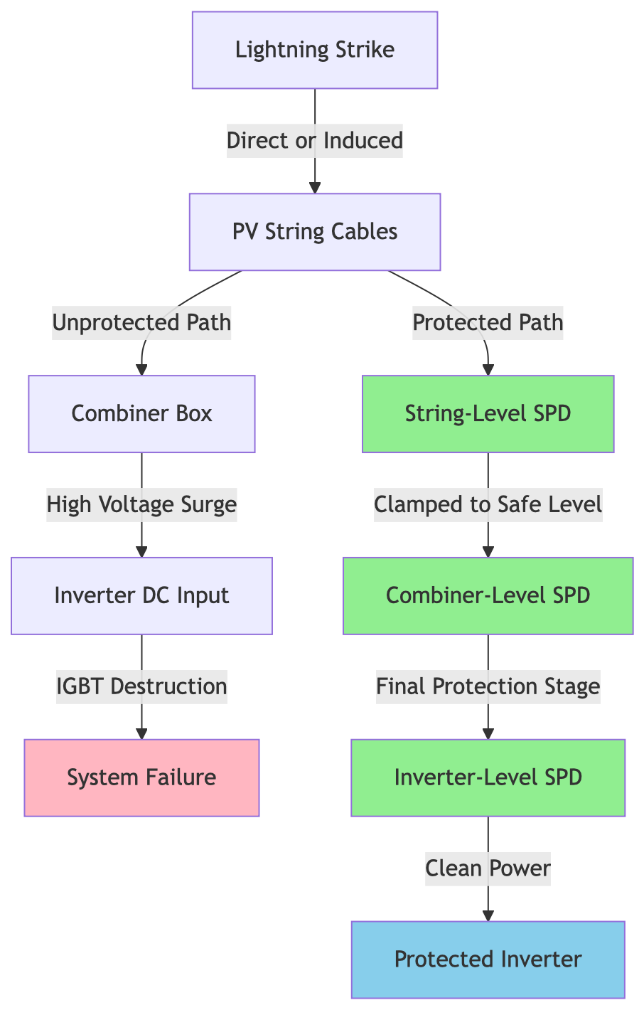
Effective pv string surge protection follows a coordinated protection cascade—think of it as a series of defensive barriers, each designed to handle specific threat levels:
First Line of Defense (String Level): Type 2 SPDs installed at or near the PV array handle the initial surge energy. These devices clamp high-voltage transients before they propagate through long cable runs where energy can accumulate.
Second Line (Combiner Box): Additional Type 2 SPDs provide backup protection and handle any residual surges that passed through the string-level devices or entered through other paths.
Final Line (Inverter Input): Type 2 or fine-protection SPDs installed at the inverter’s DC input provide the last defense, ensuring that only clean power reaches sensitive electronics.
Key Principle: Each protection stage must be properly coordinated. The Voltage Protection Level (Up) of each successive stage should be progressively lower, and devices must be separated by at least 10 meters of cable or connected through decoupling inductors to prevent SPD interaction.
The National Electrical Code (NEC) Article 690.35(A) explicitly requires surge protection for PV systems. More specifically:
IEC 61643-31 provides the international standard for SPD selection and installation in photovoltaic systems, specifying test procedures and minimum performance requirements.
Pro-Tip: During permit reviews and inspections, having properly rated and installed string-level SPDs demonstrates engineering due diligence and can expedite approval processes—inspectors look for this as a sign of quality installation.
Selecting appropriate pv string surge protection isn’t guesswork—follow this systematic approach to specify the right devices every time:
Your SPD’s maximum continuous operating voltage (Uc) must exceed the maximum open-circuit voltage (Voc) your system can produce under any conditions.
Calculation Formula:
Uc(min) = Voc(STC) × Temperature Correction Factor × Safety MarginTemperature Correction Factor: For every 10°C below 25°C (STC), Voc increases by approximately 0.35-0.40% per °C for typical crystalline silicon modules.
Ejemplo de cálculo:
Selection: Choose an SPD with Uc ≥ 1,500V DC for this 1000V nominal system.
Key Takeaway: Never select SPDs based on the nominal system voltage alone. Always calculate worst-case Voc including temperature effects and add a 15-20% safety margin to prevent SPD degradation during cold, high-irradiance conditions.
The Voltage Protection Level (Up) is the maximum voltage that will appear at the protected equipment during an SPD operation. This must be lower than the withstand voltage of your equipment.
Selection Criteria:
Up(SPD) < 0.8 × Equipment Withstand VoltageFor typical string inverters:
Recommended Up values for string-level SPDs:
Pro-Tip: Lower Up values provide better protection but may have shorter lifespans due to more frequent activation. Balance protection level with expected surge frequency in your location—high-lightning areas may need more robust specifications.
PV string SPDs must handle both direct and indirect lightning surges. The key ratings to understand:
Iimp (Impulse Current): The device’s ability to handle the high-energy surge from direct or nearby lightning strikes. Measured with a 10/350 μs waveform (Type 1 test).
Imax (Maximum Discharge Current): The device’s ability to handle multiple surges from indirect strikes. Measured with an 8/20 μs waveform (Type 2 test).
Selection Guidelines by Application:
| Aplicación | Exposure Level | Recommended Iimp | Recommended Imax | Type Class |
|---|---|---|---|---|
| Rooftop Commercial (Low-rise) | Indirect strikes only | No requerido | 20-40 kA (per pole) | Tipo 2 |
| Rooftop Commercial (High-rise) | Moderate direct strike risk | 5-12.5 kA | 40 kA | Tipo 1+2 |
| Ground-Mount (Open field) | High direct strike risk | 12.5-25 kA | 40-60 kA | Tipo 1+2 |
| Ground-Mount (High-lightning region) | Very high risk | 25 kA | 60-100 kA | Tipo 1 |
Calculation Example for String-Level Protection:
For a typical commercial rooftop array in a moderate lightning region:
The debate between Metal Oxide Varistor (MOV) and Gas Discharge Tube (GDT) technology for pv string surge protection often confuses engineers. Here’s the definitive comparison:
| Parámetro | MOV Technology | GDT Technology | Ganador |
|---|---|---|---|
| Tiempo de respuesta | < 25 nanosegundos | < 100 nanoseconds | MOV |
| Nivel de protección de tensión (arriba) | Lower (better protection) | Higher (adequate protection) | MOV |
| Discharge Capacity (per cycle) | Moderate (degrades over time) | High (robust) | GDT |
| Lifetime (number of surges) | Limited (500-2000 operations) | Excellent (>1000 high-energy operations) | GDT |
| Corriente de fuga | Moderate (increases with age) | Virtually zero | GDT |
| Follow Current (DC) | None (ideal for DC) | Can be problematic without arc quenching | MOV |
| Modo de fallo | Typically short-circuit (safe) | Can short-circuit | Both safe with proper design |
| Temperatura de funcionamiento | Good (-40°C to +85°C) | Excellent (-40°C to +90°C) | GDT |
| Cost (relative) | Baja | Más alto | MOV |
| Best Application | Moderate surge frequency | High surge frequency, critical protection | Context-dependent |
Hybrid Solution – The Professional Choice:
Modern high-performance PV SPDs combine both technologies in a staged protection approach:
Key Takeaway: For commercial and utility-scale installations where long-term reliability is critical, specify hybrid MOV+GDT technology SPDs. The slightly higher initial cost is offset by longer lifespan and superior protection performance.
Selection Decision Tree:
Understanding the datasheet specifications helps you make informed decisions about pv string surge protection:
| Technical Parameter | MOV (Metal Oxide Varistor) | GDT (Gas Discharge Tube) | Hybrid MOV+GDT |
|---|---|---|---|
| Primary Material | Zinc oxide ceramic | Inert gas (argon, neon) in ceramic tube | Both technologies staged |
| Activation Mechanism | Voltage-dependent resistance change | Gas ionization and breakdown | Sequential activation |
| Tiempo de respuesta | 5-25 nanoseconds | 50-100 nanoseconds | 5-25 ns (MOV stage first) |
| Nivel de protección de tensión (arriba) | 2.5-4.0 kV (1000V system) | 3.5-6.0 kV (1000V system) | 2,5-4,0 kV |
| Energy Handling (per operation) | 100-500 Joules | 500-2000 Joules | 500-2000 Joules |
| Maximum Discharge Current (8/20μs) | 20-60 kA | 40-100 kA | 40-100 kA |
| Impulse Current (10/350μs) | Typically not rated | 5-25 kA | 5-25 kA |
| Leakage Current (at Uc) | 10-100 μA (increases with age) | < 1 μA | < 10 μA |
| Aging Characteristics | Gradual degradation, Up increases | Minimal degradation | MOV degradation mitigated by GDT |
| Temperature Coefficient | -0.05%/°C (Uc decreases with temp) | Mínimo | -0.05%/°C |
| Follow Current in DC | None (self-extinguishing) | Can be problematic (1-2A) | Eliminated by design |
| Typical Lifetime | 500-2000 operations | >5000 operations | 2000-5000 operations |
| Failure Indication | Visual + eléctrico | Visual + eléctrico | Remote monitoring capable |
| Protección del medio ambiente | IP20-IP65 (varies) | IP20-IP65 (varies) | IP20-IP65 (varies) |
| Typical Cost (relative) | $50-150 per pole | $80-250 per pole | $150-400 per pole |
Understanding when to specify Type 1 versus Type 2 devices is critical for proper pv string surge protection:
| Característica | DOCUP de tipo 1 | DOCUP de tipo 2 | Practical Guidance |
|---|---|---|---|
| Forma de onda de prueba | 10/350 μs (high energy) | 8/20 μs (moderate energy) | Type 1 = Direct strikes, Type 2 = Indirect strikes |
| Impulse Current (Iimp) | 5-25 kA tested | Not typically rated | Type 1 mandatory for direct strike zones |
| Corriente máxima de descarga (Imax) | 50-100 kA | 20-60 kA | Both adequate for most applications |
| Specific Energy (W/R) | ≥ 2.5 kJ/Ω | ≥ 56 J/Ω | Type 1 handles 40x more energy |
| Lugar de instalación | Service entrance, main distribution | Sub-distribution, equipment level | Can be combined in Type 1+2 hybrid |
| Nivel de protección | Moderate (Up = 4-6 kV) | Better (Up = 2.5-4 kV) | Type 2 provides finer protection |
| Typical Application in PV | Ground-mount arrays, exposed locations | Rooftop systems, string combiners | Use both in cascade for optimal protection |
| Tamaño físico | Larger (higher energy capacity) | Compacto | Consider panel space requirements |
| Cost (relative) | $200-600 per device | $80-300 per device | Type 1 cost justified in high-risk areas |
| Required for NEC Compliance | If exposed to direct strikes | Minimum for most installations | Check local lightning density maps |
Pro-Tip: For optimal protection, use a Type 1+2 hybrid device at the array combiner point and Type 2 devices at the inverter input. This provides both high-energy handling and fine voltage clamping in a coordinated cascade.
Uc (Maximum Continuous Operating Voltage): The highest voltage the SPD can withstand continuously without degradation. Must exceed your system’s maximum Voc under all conditions.
Up (Voltage Protection Level): The voltage that appears at the protected equipment when the SPD operates. Lower is better, but must be balanced with energy handling capacity.
In (Nominal Discharge Current): The current used for classification and aging tests (typically 5 or 10 kA for Type 2 devices).
Imax (Maximum Discharge Current): The maximum surge current the device can handle in a single operation without damage.
Iimp (Impulse Current): For Type 1 devices, the high-energy surge current capability tested with 10/350 μs waveform.
TOV (Temporary Overvoltage) Capability: The device’s ability to withstand temporary voltage increases due to system faults or switching operations without permanent damage.
Even the highest-quality pv string surge protection devices will fail to protect your system if improperly installed. Follow this proven installation sequence: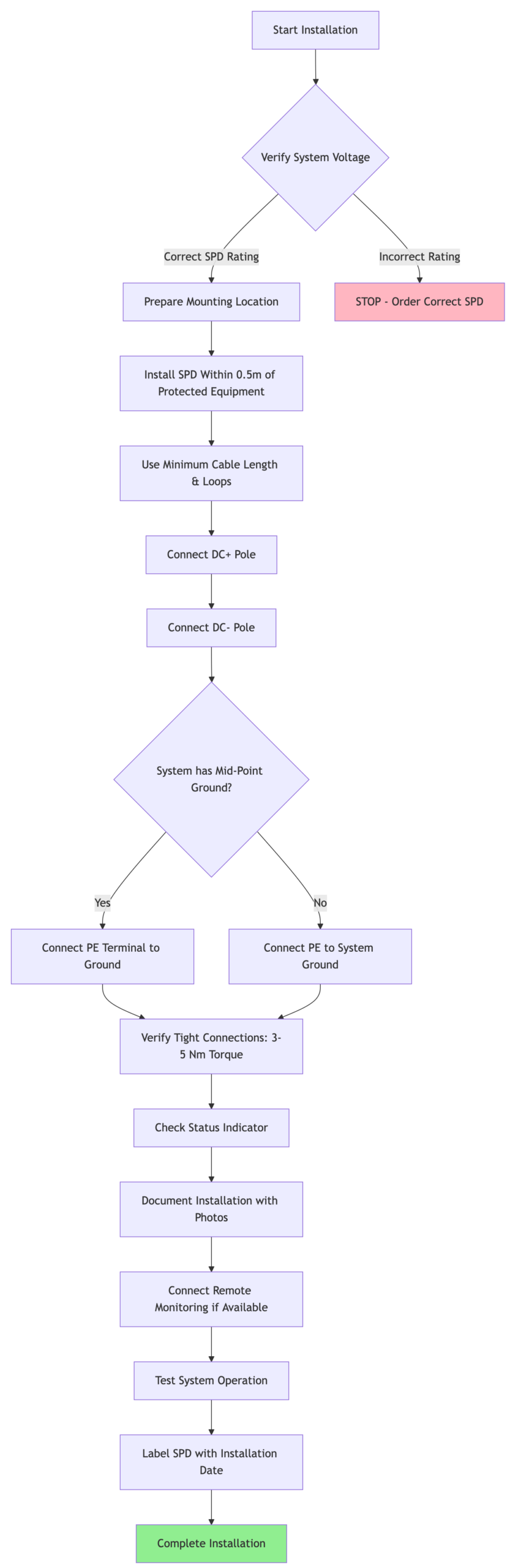
1. Cable Length and Routing (The 0.5-Meter Rule)
The connection between your SPD and the protected equipment is critical. Every meter of cable adds inductance, which creates additional voltage during fast-rising surges:
Voltage Drop Calculation:
V_additional = L × (di/dt)
Where: L ≈ 1 μH per meter of cable
       di/dt for lightning ≈ 10-100 kA/μs
Ejemplo: Just 2 meters of connection cable can add 200V of additional voltage rise during a surge, partially negating your SPD’s protection!
Installation Rules:
Pro-Tip: Pre-measure and cut your connection cables to exact length before installation. Mark the 0.5-meter limit on your installation template to ensure compliance during field installation.
2. Grounding Best Practices
Proper grounding is the foundation of effective surge protection:
For PV Systems with Mid-Point Grounding:
3. Physical Installation Considerations
Location and mounting affect both protection effectiveness and maintenance:
4. Connection Sequence
Always follow proper connection sequence to avoid ground faults or equipment damage:
Pro-Tip: Install a disconnect switch between your PV strings and the SPD to allow safe maintenance and replacement without de-energizing the entire array. This is especially valuable for large commercial systems where downtime is costly.
Let’s work through a complete design example to demonstrate proper pv string surge protection selection for a typical commercial installation.
Array Configuration:
Condiciones ambientales:
Equipment:
Step 1: Calculate Maximum System Voltage
Voc per string (STC) = 49.5V × 20 = 990V

Temperature correction:
ΔT = 25°C - (-5°C) = 30°C
Voltage increase = 990V × (30°C × 0.0035) = 104V
Voc (cold) = 990V + 104V = 1,094V

Required Uc with 20% safety margin:
Uc(min) = 1,094V × 1.20 = 1,313V
Selection: SPDs with Uc = 1,500V DC (standard rating)
Step 2: Determine Required Voltage Protection Level
Inverter withstand voltage = 6 kV
Maximum acceptable Up = 6 kV × 0.8 = 4.8 kV
Selection: SPDs with Up ≤ 4.0 kV (providing 33% safety margin)
Step 3: Select Discharge Current Rating
For rooftop installation in moderate lightning region:
For enhanced protection (optional but recommended):
Selection: Type 2 SPD with Imax = 40 kA per pole (minimum), or Type 1+2 hybrid for critical loads
Step 4: Choose Technology
For this commercial application:
Selection: Hybrid MOV+GDT technology for optimal balance of performance and longevity
graph TB
    subgraph "PV Array - 10 Strings"
        S1[String 1: 20 Modules]
        S2[String 2: 20 Modules]
        S3[String 3: 20 Modules]
        S10[String 10: 20 Modules]
    end

    S1 --> SPD1[String-Level SPD<br>Type 2, Uc=1500V<br>Up=4kV, Imax=40kA]
    S2 --> SPD2[String-Level SPD]
    S3 --> SPD3[String-Level SPD]
    S10 --> SPD10[String-Level SPD]

    SPD1 --> CB[Combiner Box]
    SPD2 --> CB
    SPD3 --> CB
    SPD10 --> CB

    CB --> SPD_CB[Combiner SPD<br>Type 2, Uc=1500V<br>Up=3.5kV, Imax=60kA]

    SPD_CB --> |10m Cable| INV[String Inverter<br>100kW, 1000VDC]

    INV --> SPD_INV[Inverter Input SPD<br>Type 2, Uc=1500V<br>Up=3.0kV, Imax=40kA]

    SPD1 -.->|Ground| GND[System Ground<br>< 5Ω Resistance]
    SPD_CB -.->|Ground| GND
    SPD_INV -.->|Ground| GND

    style SPD1 fill:#90EE90
    style SPD2 fill:#90EE90
    style SPD3 fill:#90EE90
    style SPD10 fill:#90EE90
    style SPD_CB fill:#87CEEB
style SPD_INV fill:#FFD700String-Level Protection (10 units):
Combiner Box Protection (1 unit):
Inverter Input Protection (1 unit):
Total Protection System Cost: $2,470
Key Takeaway: This comprehensive three-stage protection cascade costs less than 1.5% of the total system value but protects against damage that could cost $47,000 or more. The ROI calculation is simple: one prevented surge event pays for the entire protection system 19 times over.
When evaluating whether to specify pv string surge protection, consider the true cost of going without:
| Categoría de costes | With Proper SPD Protection | Without SPD Protection | Difference |
|---|---|---|---|
| Initial Investment | |||
| SPD Equipment | $2,470 | $0 | +$2,470 |
| Mano de obra de instalación | $800 | $0 | +$800 |
| Total Initial Cost | $3,270 | $0 | +$3,270 |
| After One Surge Event | |||
| Inverter Repair/Replacement | $0 | $12,000 | -$12,000 |
| Module Replacement (4 modules) | $0 | $2,800 | -$2,800 |
| Emergency Service Call | $0 | $1,500 | -$1,500 |
| 3-Week Production Loss | $0 | $4,200 | -$4,200 |
| Inspection & Testing | $0 | $800 | -$800 |
| Monitoring System Repair | $0 | $1,200 | -$1,200 |
| Total Surge Event Cost | $0 | $22,500 | -$22,500 |
| 10-Year Lifecycle Costs | |||
| SPD Replacement (Year 6) | $1,500 | $0 | +$1,500 |
| Expected Surge Events (2-3) | $0 | $45,000-67,500 | -$45,000 |
| Warranty Coverage | Maintained | Potentially voided | Risk value: -$35,000 |
| Insurance Premium Impact | Estándar | Potentially higher | -$2,000 |
| Total 10-Year Cost | $4,770 | $82,000-104,500 | -$77,230 |
Break-Even Calculation:
Initial SPD Investment: $3,270
Average Surge Damage Cost: $22,500
Break-even point: 0.145 surge events

If your region experiences just 1 significant surge event every 7 years,
the SPD system pays for itself.

According to IEEE data, most commercial solar installations experience
2-4 damaging surge events over a 25-year lifespan without protection.
Expected ROI Over 25 Years:
Pro-Tip: When presenting surge protection to budget-conscious clients, frame it this way: ‘We can either invest $3,000 today for protection, or budget $20,000-50,000 for repairs later. The protection system is not an expense—it’s damage insurance with a 1000% ROI.’
Warranty Coverage:
Most major manufacturers include surge protection requirements in their warranties:
Insurance Premiums:
Commercial insurance providers increasingly require documentation of surge protection:
Downtime Risk:
For critical facilities (hospitals, data centers, manufacturing) or systems under Power Purchase Agreements (PPAs):
⚡ Lightning doesn’t have to strike your array directly to cause damage. Indirect strikes up to 2km away can induce surges exceeding 6,000V on unprotected PV strings. String-level protection is your first line of defense.
💰 The cost of protection is trivial compared to damage costs. A comprehensive three-stage SPD system costs $2,000-5,000 for typical commercial installations but protects against $20,000-100,000+ in potential damage. Break-even occurs after just 0.15 surge events.
🔧 SPD selection requires four critical calculations: Maximum system voltage (Voc × temperature × safety margin), required protection level (Up < 0.8 × equipment withstand voltage), discharge current rating (based on exposure level), and technology choice (hybrid MOV+GDT for best performance).
📐 Installation quality determines protection effectiveness. Keep connection cables under 0.5 meters, use minimum 6 AWG ground conductors, avoid cable loops, and ensure all connections are torqued to specification. Poor installation can reduce protection effectiveness by 50% or more.
🎯 Coordinated cascade protection is essential. Use Type 1+2 SPDs at the array combiner, Type 2 at string level, and final Type 2 protection at the inverter input. Each stage must have progressively lower Up values and be separated by adequate cable length for proper coordination.
✅ Code compliance is mandatory, not optional. NEC Article 690.35 and IEC 61643-31 require surge protection for PV systems. Proper SPD installation is necessary for permit approval, warranty validity, and insurance coverage. Document everything with photos and commissioning reports.
🔄 Plan for SPD lifecycle maintenance. Even the best SPDs have finite lifespans (typically 5-10 years depending on surge frequency). Specify devices with visual status indicators and remote monitoring capability, and schedule annual inspections to verify continued protection.
Best practice is protection at both levels. While combiner-level protection is the minimum requirement, string-level SPDs provide the first defense against surges before they propagate through the system. For optimal protection:
String-level protection becomes especially important when strings are separated by significant distances (> 50 meters) or when array wiring is exposed. The additional cost is minimal (typically $150-200 per string) compared to the protection benefit.
Type 1 SPDs handle direct lightning strikes; Type 2 SPDs handle indirect strikes and switching surges.
Type 1 devices are tested with a 10/350 μs impulse current waveform, representing the high energy from direct strikes. They can dissipate 40-50 times more energy than Type 2 devices but are larger and more expensive. Use Type 1 SPDs when:
Type 2 devices are tested with an 8/20 μs waveform and handle indirect strikes (the most common threat). They provide better voltage clamping (lower Up) and are sufficient for most rooftop installations.
Modern hybrid “Type 1+2” devices provide both capabilities in a single unit—ideal for combiner box protection where both direct and indirect surge threats exist.
Absolutely not—AC and DC SPDs are fundamentally different and not interchangeable.
AC SPDs rely on the natural current zero-crossing that occurs 100-120 times per second in AC systems to extinguish any follow current after surge protection. DC systems have no zero-crossing, meaning:
DC SPDs must be specifically designed and rated for photovoltaic applications with:
Using AC SPDs on DC circuits is a code violation, warranty voidance, and serious safety hazard. Always specify DC-rated, PV-specific surge protection devices.
Most quality SPDs have visual status indicators—but don’t rely on visual inspection alone.
Modern pv string surge protection devices include multiple failure indication methods:
Indicadores visuales:
Electrical Indicators:
Calendario de inspecciones:
When to Replace:
Pro-Tip: Document SPD installation dates on device labels and in maintenance logs. Set calendar reminders for preventive replacement based on manufacturer recommendations—don’t wait for failure in critical applications.
Choose SPD voltage ratings based on worst-case Voc, not nominal system voltage.
Para 1000V nominal systems:
Typical maximum Voc (cold): 1,100-1,200V
Recommended SPD Uc rating: 1,500V DC
Standard protection level (Up): 3.5-4.0 kV
Para 1500V nominal systems:
Typical maximum Voc (cold): 1,650-1,800V
Recommended SPD Uc rating: 2,000V DC
Standard protection level (Up): 5.0-6.0 kV
Critical calculation steps:
Example for 1500V system:
Never undersize SPD voltage ratings to save cost—undersized SPDs will degrade rapidly or fail prematurely when exposed to high Voc conditions.
Neither is universally “better”—the optimal choice depends on your specific application requirements.
Choose MOV-only SPDs when:
Choose GDT-only SPDs when:
Choose Hybrid MOV+GDT SPDs when:
The industry trend is toward hybrid designs because they combine the best characteristics of both technologies:
For professional installations where system uptime and long-term protection are priorities, specify hybrid technology—the 20-30% higher initial cost is recovered through extended lifespan and superior protection performance.
Maximum 0.5 meters (50 cm) of total cable length between SPD and protected equipment—shorter is always better.
The critical principle: Every meter of connecting cable adds inductance (approximately 1 μH/meter), which creates additional voltage rise during fast surge events:
Voltage rise calculation:
V_additional = L × (di/dt)

Example with 2 meters of cable:
L = 2 meters × 1 μH/meter = 2 μH
di/dt = 50 kA/μs (typical lightning surge rate)
V_additional = 2 μH × 50,000 A/μs = 100V per meter

Total additional voltage = 200V
This additional voltage appears at the protected equipment encima de the SPD’s voltage protection level (Up), effectively reducing protection performance.
Installation best practices:
Consejo profesional: corte previamente los cables de conexión del SPD a la longitud exacta necesaria antes de la instalación. Utilice cables cortos y directos, incluso si ello requiere cambiar la posición de montaje del SPD: la eficacia de la protección es más importante que una gestión ordenada de los cables.
En sistemas grandes con múltiples cajas combinadoras, coloque los SPD en cada caja combinadora en lugar de utilizar cables largos hasta una ubicación centralizada para los SPD. La protección distribuida es más eficaz que la protección centralizada con cables largos.
Los SPD seleccionados e instalados correctamente no afectan en absoluto al rendimiento del sistema durante su funcionamiento normal.
Durante el funcionamiento normal:
Consideraciones sobre la corriente de fuga:
Durante eventos de aumento repentino:
Posibles problemas solo si se aplica incorrectamente:
En resumen: Los SPD de calidad son transparentes para el funcionamiento del sistema. Cualquier impacto en el rendimiento derivado de una protección contra sobretensiones instalada correctamente se ve ampliamente compensado por las ventajas que ofrece dicha protección. El único “problema de rendimiento” que experimentará es el funcionamiento continuado tras eventos de sobretensión que, de otro modo, habrían destruido su equipo.
Reflexión final: En la industria fotovoltaica, a menudo oímos decir que “cada dólar que se ahorra en costes de instalación es beneficio”. Pero prescindir de la protección contra sobretensiones de las cadenas fotovoltaicas para ahorrar entre $2000 y 3000 dólares iniciales es como cancelar el seguro del coche para ahorrar en primas: funciona muy bien hasta que lo necesitas. La cuestión no es si puede permitirse la protección contra sobretensiones, sino si puede permitirse sustituir todo un inversor, docenas de módulos y absorber semanas de inactividad cuando cae un rayo. Haga de la protección contra sobretensiones una parte innegociable del diseño de todos los sistemas fotovoltaicos: sus clientes (y su reputación) se lo agradecerán.