WengYang Industriegebiet Yueqing Wenzhou 325000
Arbeitszeiten
Montag bis Freitag: 7AM - 7PM
Am Wochenende: 10AM - 5PM
WengYang Industriegebiet Yueqing Wenzhou 325000
Arbeitszeiten
Montag bis Freitag: 7AM - 7PM
Am Wochenende: 10AM - 5PM

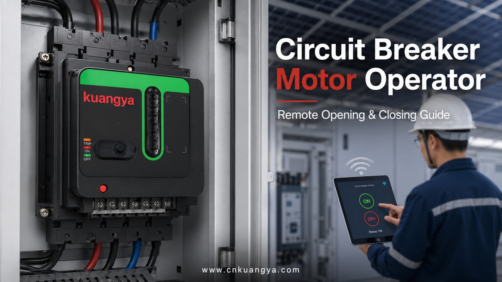
A Motorantrieb für einen Leistungsschalter ist ein elektrisch betriebenes Zubehörteil, das einen kompatiblen Leistungsschalter mechanisch betätigt.
Nach Erhalt eines elektrischen Befehls bewegt der Motorantrieb den Schaltmechanismus, um eine Fernöffnung oder -schließung durchzuführen. Abhängig vom Leistungsschalter, dem Motorantrieb und der Steuerungskonfiguration kann er auch das Rücksetzen, die manuelle Vor-Ort-Bedienung, die Statusanzeige sowie die Integration in intelligente Steuerungssysteme unterstützen.
Ein Motorantrieb ersetzt nicht die elektrischen Schutzfunktionen des Leistungsschalters. Der Schalter bietet weiterhin Überlast-, Kurzschluss- oder andere anwendbare Schutzfunktionen, während der Motorantrieb eine Möglichkeit zur Fernbedienung bietet.
Motorantriebe etablierter Leistungsschalterhersteller werden häufig für das Fernschalten, die Automatisierung der Stromverteilung, die Umschaltung zwischen Normal- und Ersatzstromquelle sowie für Lastmanagementanwendungen eingesetzt.
| Artikel | Beschreibung |
|---|---|
| Hauptproduktname | Motorantrieb für Leistungsschalter |
| Weitere gebräuchliche Bezeichnungen | Motorantrieb für Leistungsschalter, MCCB-Motorantrieb, elektrischer Betätigungsmechanismus |
| Hauptzweck | Betätigung eines kompatiblen Leistungsschalters durch einen elektrischen Befehl |
| Hauptfunktionen | Fernauslösung und Ferneinschaltung |
| Zusatzfunktionen | Rückstellung, lokale Bedienung und Statusanzeige, je nach Konfiguration |
| Installationsmethode | Montage an der Vorderseite, Seite oder Montageplatte eines kompatiblen Leistungsschalters |
| Gemeinsame Steuerquellen | Drucktaster, Relais, SPS, SCADA, ATS-Steuerung oder Überwachungssystem |
| Typische Anwendungen | PV-Verteilerschränke, Industrieschaltschränke, Umschalteinrichtungen und unbemannte Standorte |
| Hauptstromkreisschutz | Bereitgestellt durch den Leistungsschalter |
| Steuerstromversorgung | Eine separate AC- oder DC-Hilfsstromversorgung ist normalerweise erforderlich |
| Kompatibilität | Muss anhand des Leistungsschaltermodells, der Baugröße und der Hebelbewegung überprüft werden |
| Manuelle Betätigung | Bei vielen Ausführungen verfügbar, die Methode variiert jedoch je nach Produkt |
Herkömmliche Leistungsschalter werden normalerweise manuell betätigt. Ein Techniker muss vor dem Schaltschrank stehen und den Schalthebel in die Position EIN, AUS oder Reset bewegen.
Dieser Ansatz ist für kleine, leicht zugängliche Verteilerkästen, die selten geschaltet werden müssen, praktikabel. Die manuelle Bedienung wird jedoch ineffizient, wenn elektrische Anlagen über ein großes Werk verteilt oder an abgelegenen, unbeaufsichtigten Standorten installiert sind.
Beispiele hierfür sind:
Bei diesen Projekten kann selbst ein einfacher Schaltvorgang erfordern, dass Personal den Schaltschrank lokalisiert, zum Standort reist, eine Zugangsberechtigung einholt und den Leistungsschalter manuell betätigt.
Ein motorischer Antrieb ermöglicht es einem kompatiblen Leistungsschalter, einen elektrischen Befehl von einem Fernbedienungspanel oder einem Automatisierungssystem zu empfangen. Dies hilft, ausgewählte Schaltvorgänge zu zentralisieren und wiederholte manuelle Eingriffe zu reduzieren.
| Vergleichspunkt | Manuelle Betätigung des Leistungsschalters | Motorische Betätigung des Leistungsschalters |
|---|---|---|
| Einsatzort | Direkt vor dem Schutzschalter | Lokal oder von einer Fernsteuerstelle aus |
| Erforderliches Personal | Techniker muss Zugang zum Schaltschrank haben | Bestimmte Vorgänge können aus der Ferne ausgeführt werden |
| Steuerungsmethode | Mechanische Handbedienung | Elektrischer Befehl plus mechanische Betätigung |
| SPS-Integration | Normalerweise ohne Zubehör nicht verfügbar | Mit geeigneter Steuerverdrahtung möglich |
| Zentralisierte Steuerung | Begrenzt | Geeignet für zentrale elektrische Steuerung |
| Positionsrückmeldung | Visuelle Kontrolle | Elektrische Rückmeldung kann ergänzt werden |
| Geeignete Projekte | Kleine und leicht zugängliche Systeme | Große, fernbediente oder automatisierte Anlagen |
| Manuelle Reserve | Standard | Oft beibehalten, abhängig von der Konstruktion des Mechanismus |
| Komplexität der Installation | Unter | Erfordert mechanische Anpassung und Steuerverdrahtung |
| Anschaffungskosten | Unter | Höher, kann jedoch wiederholte Vor-Ort-Einsätze reduzieren |
Der Fernbetrieb entbindet nicht von der Notwendigkeit von qualifiziertem Personal, elektrischer Verriegelung oder sicheren Wartungsverfahren. Er ändert lediglich die Art und Weise, wie der Leistungsschalter einen Schaltbefehl empfängt und ausführt.
Ein motorischer Stellantrieb, auch als Leistungsschalter-Motorantrieb, bezeichnet, wird an einem kompatiblen Leistungsschalter installiert oder mit diesem verbunden.
Sein Zweck ist es, einen elektrischen Steuerbefehl in eine kontrollierte mechanische Bewegung umzuwandeln.
Bei der Art von externen Motorantrieben, die üblicherweise bei Kompaktleistungsschaltern verwendet werden, treibt der interne Motor ein Zahnrad, einen Nocken oder ein Gestänge an. Dieser Mechanismus bewegt dann den Schalthebel des Leistungsschalters zwischen seinen unterstützten Schaltstellungen.
Die detaillierte Konstruktion variiert je nach Schaltertyp und Hersteller. Einige externe Mechanismen betätigen den Schalthebel direkt, während Motorantriebe für größere offene Leistungsschalter Funktionen wie das elektrische Spannen der Einschaltfedern ausführen können. Aus diesem Grund müssen das Funktionsprinzip und die Zubehörkonfiguration immer für das jeweilige Schaltersystem überprüft werden.
| Komponente | Hauptfunktion |
|---|---|
| Elektromotor | Erzeugt die für den Betrieb des Mechanismus erforderliche Kraft |
| Getriebe | Wandelt die Motordrehung in eine kontrollierte Bewegung um |
| Nocken oder Gestänge | Überträgt die Bewegung auf den Schalthebel |
| Montagestruktur | Fixiert den Antrieb in der korrekten Position |
| Steueranschlüsse | Empfang von Stromversorgung sowie Öffnungs- oder Schließbefehlen |
| Endschalter | Stoppt den Motor, wenn die Zielposition erreicht ist |
| Positionsanzeige | Zeigt den Betriebszustand des Mechanismus an |
| Manuelle Betätigungsvorrichtung | Ermöglicht bei Bedarf die lokale Bedienung |
| Lokal/Fern-Wahlschalter | Ändert die zulässige Quelle für Steuerbefehle |
| Hilfskontakte | Bietet eine Rückmeldung über den Status EIN, AUS oder AUSGELÖST, sofern enthalten |
| Schutzabdeckung | Verringert das versehentliche Berühren beweglicher Teile |
| Verriegelungsschnittstelle | Unterstützt die Koordinierung des Betriebs mit anderen Leistungsschaltern oder Steuerungen |
Nicht jeder Motorantrieb enthält alle oben aufgeführten Komponenten. Der tatsächliche Aufbau hängt vom Produktdesign und den erforderlichen Funktionen ab.
Ein typischer motorisierter Schaltvorgang besteht aus fünf Phasen.
Der Schaltbefehl kann von folgenden Quellen stammen:
Der Befehl weist den Mechanismus normalerweise an, den Leistungsschalter zu öffnen oder zu schließen.
Nach Erhalt des Befehls wird der interne Motor über die Hilfssteuerspannung versorgt.
Die Steuerspannung muss mit der Nennspannung des Motorantriebs übereinstimmen. Die Hauptkreisspannung des Leistungsschalters und die Hilfssteuerspannung des Antriebs sind getrennte Spezifikationen.
Der Motor treibt die internen Zahnräder, den Nocken oder das Gestänge an.
Dies wandelt die Drehbewegung des Motors in die mechanische Bewegung um, die für die Betätigung des Leistungsschalterhebels erforderlich ist.
Der Betätigungsmechanismus bewegt den Leistungsschalter in die gewünschte EIN- oder AUS-Stellung.
Sobald die Zielposition erreicht ist, stoppt ein Endschalter oder eine interne Positionssteuerung den Motor. Dies verhindert, dass der Motor nach Abschluss des Vorgangs weiterhin Kraft ausübt.
Wenn geeignete Hilfskontakte installiert sind, kann der Leistungsschalter oder Motorantrieb ein Rückmeldesignal an das Steuerungssystem senden.
Kommunikationsfähige Leistungsschaltersysteme können Öffnungs-, Schließ- und Rücksetzbefehle empfangen sowie Zustände wie AUS, EIN und Ausgelöst übertragen. Die verfügbaren Rückmeldefunktionen hängen vom Leistungsschalter und dem Steuermodul ab.
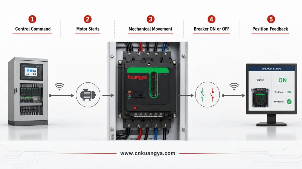
| Schritt | Aktion des Steuerungssystems | Aktion des Motorantriebs | Schaltzustand |
|---|---|---|---|
| 1 | Sendet einen Öffnungs- oder Schließbefehl | Empfängt das Steuersignal | Verbleibt in seiner vorherigen Position |
| 2 | Liefert die erforderliche Steuerspannung | Interner Motor startet | Beginnt die Positionsänderung |
| 3 | Hält das erforderliche Betriebssignal aufrecht | Getriebe und Gestänge übertragen die Bewegung | Schalthebel bewegt sich in Richtung der Zielposition |
| 4 | Überwacht den Betriebsvorgang | Endschalter stoppt den Motor | Erreicht EIN oder AUS |
| 5 | Empfängt ein Hilfskontaktsignal | Gibt eine Positionsanzeige zurück oder unterstützt diese | Endposition ist bestätigt |
| 6 | Protokolliert das Ergebnis bei Anschluss an ein Überwachungssystem | Kehrt in den Standby-Zustand zurück | Bereit für den nächsten zulässigen Schaltvorgang |
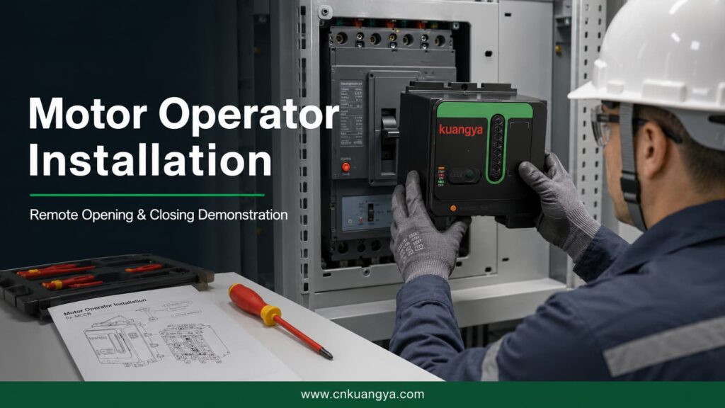
Das folgende Video zeigt die vollständige Installation eines universellen Motorantriebs, der für kompatible Leistungsschalter ausgelegt ist.
Es zeigt, wie der Betätigungsmechanismus positioniert und mit dem Leistungsschalter verbunden wird, gefolgt von einer Demonstration des Fernöffnens und -schließens.
Diese Art von Motorantrieb kann in Photovoltaik-Stromverteilerschränken, industriellen Schalttafeln und intelligenten elektrischen Steuerungsprojekten eingesetzt werden.
| Demonstrationsphase | Was der Betrachter sehen kann |
|---|---|
| Produktvorbereitung | Der Motorantrieb und der Leistungsschalter vor der Installation |
| Bestätigung der Montageposition | Der Antrieb ist auf den Leistungsschalter ausgerichtet |
| Mechanische Installation | Der Motorantrieb ist in der erforderlichen Position befestigt |
| Griffverbindung | Das Betätigungsgestänge ist mit dem Schaltergriff verbunden |
| Installationsanpassung | Der Mechanismus wird auf korrekten Verfahrweg und Ausrichtung geprüft |
| Fernauslösung | Der Motorantrieb bewegt den Leistungsschalter von EIN nach AUS |
| Fernschaltung | Der Motorantrieb bewegt den Leistungsschalter von AUS nach EIN |
| Funktionsbestätigung | Der Leistungsschalter führt die erforderliche mechanische Bewegung aus |
| Endkontrolle | Der installierte Mechanismus wird auf stabilen Betrieb geprüft |
Eine korrekte Ausrichtung ist unerlässlich. Wenn der Mechanismus in der falschen Position installiert ist, führt der Leistungsschalter die Öffnungs-, Schließ- oder Rückstellbewegung möglicherweise nicht vollständig aus.
Die genauen Funktionen eines Motorantriebs für einen Leistungsschalter hängen vom Schaltermodell, dem Schaltmechanismus, der Verdrahtung und dem Steuerungssystem ab.
Der Motorantrieb kann einen kompatiblen Leistungsschalter nach Erhalt eines Auslösebefehls aus der geschlossenen in die geöffnete Position bringen.
Die Fernauslösung ist nützlich, wenn ein Stromkreis von einem Kontrollraum, einem zentralen Schaltfeld oder einer Überwachungsstation aus getrennt werden muss.
Der Motorantrieb kann einen kompatiblen Leistungsschalter nach Erhalt eines Einschaltbefehls und nach Erfüllung der erforderlichen Systembedingungen schließen.
Die Fernschließung sollte durch eine geeignete Logik und Verriegelung gesteuert werden. Ein Schließbefehl sollte nicht allein deshalb erteilt werden, weil der Leistungsschalter geöffnet ist.
Nach bestimmten Auslöseereignissen muss der Schaltmechanismus eine Rückstellsequenz durchlaufen, bevor er wieder geschlossen werden kann.
Einige Motorantriebe unterstützen die Rückstellung, die Methode variiert jedoch erheblich. Die Rückstellung kann je nach Leistungsschalter und Steuerungsanordnung manuell, per Fernzugriff oder automatisch erfolgen.
Die Dokumentation von Schneider Electric unterscheidet beispielsweise zwischen lokaler Rückstellung, Fernrückstellung und Konfigurationen, bei denen die Rückstellung nach einer elektrischen Auslösung eingeschränkt ist, sofern das System nicht speziell dafür konfiguriert wurde.
Offiziell Bedienungsanleitung für Motorantriebe von Schneider Electric zeigt, dass ein kommunikationsfähiger Motorantrieb Öffnungs-, Schließ- und Rückstellbefehle empfangen sowie Informationen zum EIN-, AUS- und Auslösezustand übertragen kann.
Viele Motorantriebe verfügen weiterhin über eine lokale manuelle Betätigungsfunktion.
This may be required during:
The manual operating procedure must follow the instructions for the actual mechanism.
Some mechanisms include a selector that determines whether operation is controlled locally or remotely.
This can help prevent unintended remote commands during maintenance or commissioning.
Position feedback allows a control or monitoring system to determine whether the breaker is:
The available signals depend on the auxiliary contacts and communication modules used in the system.
| Funktion | Beschreibung | Typical Availability |
|---|---|---|
| Fernauslösung | Opens the breaker after an electrical command | Gemeinsame |
| Fernschaltung | Closes the breaker after an electrical command | Gemeinsame |
| Remote reset | Resets a tripped breaker remotely | Model- and configuration-dependent |
| Automatic reset | Resets after a permitted event according to control logic | Model- and system-dependent |
| Manuelle Betätigung | Allows the mechanism to be operated locally | Common on many designs |
| Local/remote selection | Selects the source of operating commands | Model-dependent |
| ON indication | Reports or displays the closed position | Requires appropriate indication |
| OFF indication | Reports or displays the open position | Requires appropriate indication |
| TRIP indication | Reports that the breaker has tripped | Requires trip-status contact |
| SPS-Integration | Accepts commands from an automation controller | Requires compatible control circuit |
| SCADA integration | Supports remote supervisory control | Requires suitable interface equipment |
| Electrical interlocking | Prevents conflicting operating commands | Requires correct system design |
The presence of a motor operator does not automatically mean that every function in this table is available. The actual functions must be confirmed from the product datasheet and wiring diagram.
Motor operators are often confused with other circuit-breaker accessories.
Although these devices can all be connected to a control circuit, they have different purposes.
| Accessory | Hauptzweck | Fernauslösung | Ferneinschaltung | Funktion zurücksetzen | Status Feedback |
|---|---|---|---|---|---|
| Motor operator | Mechanically operates the circuit breaker | Ja | Ja | Je nach Modell | Possible |
| Shunt-Auslösung | Trips or opens the breaker after receiving a voltage signal | Ja | Nein | Nein | Nein |
| Undervoltage release | Opens or prevents closing when its supply voltage is too low | Yes, under specified conditions | Nein | Nein | Nein |
| Closing release | Initiates closing on supported breaker systems | Nein | Ja | Nein | Nein |
| Auxiliary contact | Indicates whether the breaker is open or closed | Nein | Nein | Nein | Ja |
| Alarm contact | Indicates that a protective trip has occurred | Nein | Nein | Nein | Ja |
| Trip-indication contact | Reports a trip caused by a specified condition | Nein | Nein | Nein | Ja |
A shunt trip is designed to open a circuit breaker when its coil receives the specified voltage. It does not normally close or mechanically reset the breaker.
Eine undervoltage release responds when its control voltage falls below the required operating range. Depending on the product, it can open the breaker or prevent it from closing.
Eine auxiliary switch provides remote electrical indication of whether the breaker is open or closed. It reports status but does not operate the breaker.
Eaton documentation similarly distinguishes a motor operator, which supports electrical operation, from a shunt trip that opens the breaker and an auxiliary switch that provides remote position indication.
| Project Requirement | More Relevant Accessory |
|---|---|
| Remotely open the breaker only | Shunt trip may be sufficient |
| Remotely open and close the breaker | Motor operator or breaker-specific electrical operating system |
| Prevent closing when control voltage is lost | Undervoltage release |
| Report ON and OFF positions | Auxiliary contact |
| Report an electrical-fault trip | Alarm or trip-indication contact |
| Reset and reclose a supported breaker remotely | Compatible motor operator plus appropriate control logic |
| Transfer between two power sources | Motor operators, controllers and interlocking may be required |
| Integrate the breaker into PLC control | Motor operator plus status and control interfaces |
A motorized operating mechanism can be used wherever a compatible circuit breaker needs to be operated remotely or integrated into an automated electrical-control system.
| Anmeldung | Why the Motor Operator Is Used | Typical Control Source |
|---|---|---|
| Photovoltaic distribution cabinet | Supports remote switching and centralized PV-system control | PLC or solar monitoring system |
| Industrial control panel | Reduces repeated manual operation across multiple cabinets | PLC or control relay |
| Automatic transfer system | Coordinates switching between normal and backup sources | ATS controller |
| Generator distribution system | Controls selected breakers during generator operation | Generator controller |
| Energy storage system | Supports remote isolation and auxiliary-circuit control | EMS or PLC |
| Telecommunications site | Allows operation at remote or unattended facilities | Remote monitoring system |
| Intelligent building | Integrates breaker operation into centralized building control | BMS |
| Water treatment facility | Supports automated control of distributed electrical equipment | PLC or SCADA |
| Mining or remote infrastructure | Reduces the need for personnel to access distant cabinets | Remote control panel |
| Agricultural power system | Supports centralized operation across distributed equipment | PLC or relay control |
| Data center auxiliary distribution | Supports coordinated switching of selected non-critical circuits | Power-management system |
| Manufacturing production line | Allows circuit operation as part of an automated sequence | PLC |
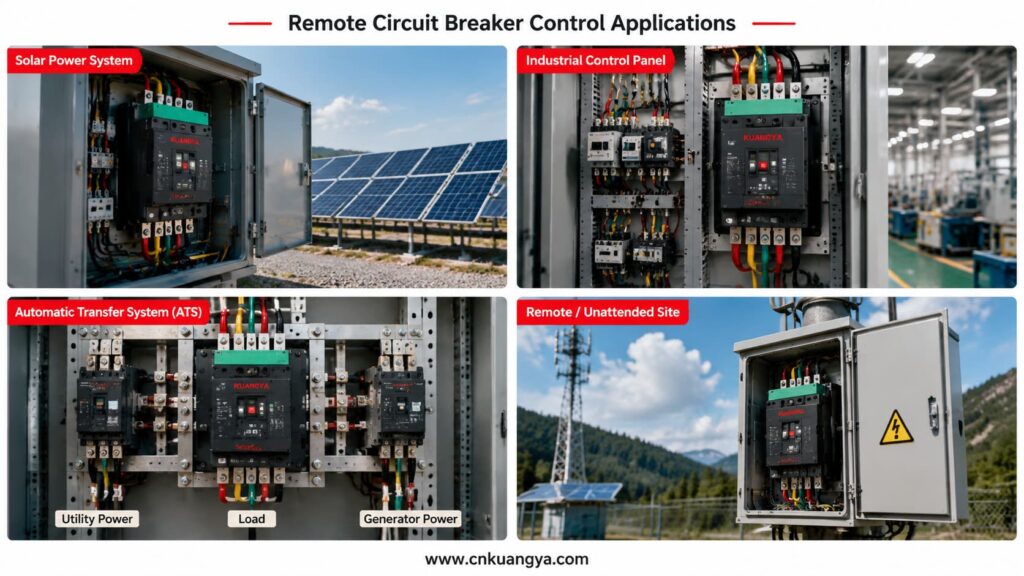
Photovoltaic installations can contain inverters, distribution cabinets, monitoring equipment and auxiliary electrical systems across large areas.
When a breaker must be operated manually, technicians may need to travel to the cabinet even when the required action is relatively simple.
Remote breaker operation should be considered as one part of a coordinated solar PV electrical protection system, together with overcurrent protection, surge protection, electrical isolation and power distribution equipment.
A compatible motor operator can allow selected opening or closing commands to be issued from a monitoring station or control system.
Possible applications include:
For projects that integrate circuit breakers, fuses, SPDs and isolation devices inside one enclosure, explore our PV-Generatoranschlusskasten-Lösungen for residential, commercial and remote solar installations.
However, remote operation must not be confused with unrestricted automatic reclosing.
If a breaker has tripped because of a short circuit, overload, insulation failure or equipment damage, the cause should be identified before the circuit is energized again.
Circuit-breaker manufacturers specifically warn against reclosing after an electrical fault without first inspecting and repairing the downstream equipment when necessary.
Factories often contain numerous electrical panels serving production lines, pumps, ventilation systems, conveyors and other equipment.
A circuit breaker motor operator can allow selected circuits to be controlled from:
The motor operator can form part of a larger sequence. For example, the system may open a breaker before equipment maintenance or close a breaker only after other safety conditions have been confirmed.
Remote operation should be coordinated with:
Automatic transfer systems switch a load between two power sources, such as:
Motor-operated breakers may be used as the switching devices in these systems.
A suitable controller sends opening and closing commands according to source availability and system conditions.
The system must normally include interlocking to prevent two incompatible sources from being connected at the same time.
| Sequence | Source A Breaker | Source B Breaker | Controller Action |
|---|---|---|---|
| 1 | Closed | Open | Monitors Source A |
| 2 | Opens after Source A failure | Remains open | Confirms Source A breaker is open |
| 3 | Open | Closes | Transfers load to Source B |
| 4 | Remains open | Closed | Monitors source recovery |
| 5 | Open | Opens | Prepares transfer back |
| 6 | Closes | Open | Restores supply from Source A |
Motor-operated breakers are also commonly used in automatic transfer switch solutions to coordinate switching between normal, standby and generator power sources.
This is only a simplified example. An actual transfer system requires project-specific timing, protection, interlocking and control logic.
The term universal motor operator is often used for an adjustable mechanism designed to work with several compatible breaker dimensions or frame sizes.
However, “universal” should not be interpreted as “suitable for every circuit breaker.”
Circuit breakers from different manufacturers and product series can have different:
A universal design may provide adjustable mounting positions, but compatibility still needs to be checked.
A safer technical description is:
A universal motor operator designed for a range of compatible circuit breakers.
| Compatibility Factor | Why It Must Be Confirmed |
|---|---|
| Breaker brand | Different manufacturers use different mechanical designs |
| Complete breaker model | Identifies the specific series and construction |
| Größe des Rahmens | Affects breaker dimensions and operating force |
| Handle position | Must align with the operator mechanism |
| Handle dimensions | Must fit the operating interface correctly |
| Handle travel | The operator must complete the full ON and OFF movement |
| Reset movement | The mechanism must support the required trip-reset sequence |
| Mounting holes | Determine whether the operator can be securely installed |
| Breaker depth | Affects the installation and alignment position |
| Anzahl der Pole | May affect overall breaker construction |
| Front accessories | Covers or rotary handles may interfere with installation |
| Required torque | The operator must provide sufficient operating force |
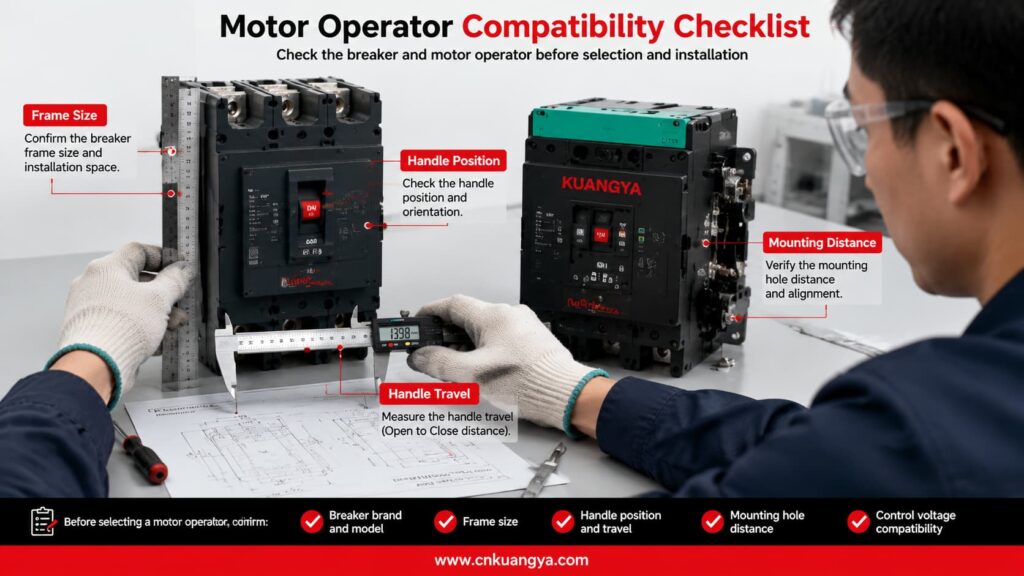
The supplier should receive clear photographs and dimensional information before confirming that a universal motor operator is suitable.
Selecting the correct motorized operating mechanism requires more than knowing the breaker’s rated current.
A 250 A or 400 A description alone is normally insufficient because breakers with the same rated current can have different frame sizes, dimensions and operating mechanisms.
The complete breaker model is one of the most important pieces of information.
Provide:
A nameplate photograph is highly recommended.
The frame size influences:
The breaker’s rated current and frame size are related but are not always identical.
Before selecting the operating mechanism, engineers must first confirm the breaker voltage, rated current, frame size, breaking capacity and accessory requirements. Read our DC MCCB selection guide for a more detailed explanation.
The motor operator normally requires a separate auxiliary power supply.
The buyer must specify:
Writing only “220 V” is incomplete. It should be written as 220 VAC oder 220 VDC.
The buyer should state whether the project requires:
The supplier needs to know whether commands will come from:
Remote systems should not rely only on sending commands.
Feedback may be required for:
Provide information about:
| Selection Item | Information Required from Buyer | Warum es wichtig ist |
|---|---|---|
| Breaker brand | Manufacturer name | Identifies the basic mechanical design |
| Complete model | Full breaker model number | Confirms the exact breaker series |
| Größe des Rahmens | Breaker frame specification | Determines dimensions and operating force |
| Nennstrom | Breaker current rating | Helps confirm the breaker configuration |
| Anzahl der Pole | 2P, 3P or 4P | Helps identify the physical version |
| Front photograph | Clear image of the breaker handle and cover | Supports mechanical compatibility checking |
| Side photograph | Clear side view | Helps check depth and mounting arrangement |
| Nameplate photograph | Full readable nameplate | Confirms electrical and model information |
| Control voltage | Voltage value plus AC or DC | Must match the auxiliary power supply |
| Required functions | Opening, closing, reset and manual operation | Determines the mechanism configuration |
| Control source | Button, relay, PLC, SCADA or ATS | Determines wiring and signal requirements |
| Feedback requirement | ON, OFF or TRIP signals | Determines auxiliary contact requirements |
| Anmeldung | PV, industrial, ATS or other use | Helps evaluate the operating requirements |
| Menge | Number of units | Required for quotation and production planning |
| Certification requirement | Required market or project documentation | Determines applicable product and document needs |
The circuit breaker used with a motorized operating mechanism should comply with the applicable low-voltage circuit breaker standards. IEC 60947-2 specifies requirements for industrial and similar low-voltage circuit breakers. The compatibility, control voltage and installation requirements of the motor operator must also be confirmed separately.
Different motor-operator models may be manufactured for different AC or DC control supplies.
The following table provides general examples only. It is not a fixed KUANGYA product-voltage list.
| Example Control Supply | Aktueller Typ | Common Control Environment |
|---|---|---|
| 24 VDC | Direct current | PLC and automation systems |
| 48 VDC | Direct current | Telecommunications and industrial control |
| 110 VDC | Direct current | Utility and substation control systems |
| 220 VDC | Direct current | Specialized industrial control systems |
| 110 VAC | Alternating current | Industrial distribution equipment |
| 220 VAC | Alternating current | General control panels |
| 230 VAC | Alternating current | International low-voltage systems |
The available operating range, inrush current, power consumption and command duration must be confirmed from the datasheet for the selected model.
Installation should be carried out by qualified personnel according to the product wiring diagram, breaker instructions and local electrical requirements.
Installers can also refer to this official motor operator installation instruction for an example of mechanical mounting, control wiring and remote opening, closing and resetting procedures.
Before installation:
After installation:
Motor-mechanism wiring should not be changed casually. Manufacturer documentation warns that incorrect modifications can create repeated closing on an electrical fault and requires the mechanism to be wired according to its specified diagram.
| Prüfpunkt | Before Installation | After Installation |
|---|---|---|
| Breaker compatibility confirmed | ✓ | - |
| Breaker model recorded | ✓ | - |
| Control voltage verified | ✓ | - |
| Main circuit isolated | ✓ | - |
| Control circuit isolated | ✓ | - |
| Wiring diagram reviewed | ✓ | - |
| Mounting position aligned | ✓ | ✓ |
| Mechanical linkage secured | - | ✓ |
| Full opening movement completed | - | ✓ |
| Full closing movement completed | - | ✓ |
| Reset sequence tested when applicable | - | ✓ |
| Manual operation tested | - | ✓ |
| Remote opening tested | - | ✓ |
| Remote closing tested | - | ✓ |
| Position feedback tested | - | ✓ |
| Interlocking tested | - | ✓ |
| Abnormal noise checked | - | ✓ |
| Mechanical resistance checked | - | ✓ |
Some breaker and motor-operator configurations can support reset and remote reclosing.
However, the fact that a breaker can be closed remotely does not mean that immediate reclosing is safe.
A circuit breaker may trip because of:
Before resetting and closing the breaker, the system or responsible personnel should determine whether the fault has been cleared.
For critical applications, the control logic may include:
After an electrical-fault trip, some manufacturer configurations require local reset by default, while remote reset must be specifically enabled through the relevant communication and control system.
| Siehe | Question Before Reclosing |
|---|---|
| Trip cause | Has the reason for the trip been identified? |
| Fault condition | Has the short circuit, overload or equipment fault been cleared? |
| Downstream circuit | Has the connected equipment been inspected when necessary? |
| Breaker condition | Is the breaker mechanically ready to reset and close? |
| Voltage condition | Is the source voltage within the permitted range? |
| Interlocking | Are all interlocking conditions satisfied? |
| Positionsrückmeldung | Is the breaker’s actual position confirmed? |
| Number of attempts | Has the system exceeded the permitted reclosing attempts? |
| Personnel safety | Are personnel clear of the affected equipment? |
| Authorization | Has the required automatic or manual permission been received? |
Troubleshooting should begin only after the main and control circuits have been made safe.
The following table lists possible causes. It does not replace the actual product manual or electrical testing.
| Problem | Mögliche Ursache | Empfohlene Prüfung |
|---|---|---|
| Motor does not operate | No auxiliary power | Measure and confirm the control supply |
| Motor does not operate | Incorrect terminal wiring | Compare the wiring with the product diagram |
| Breaker does not fully close | Operator is not correctly aligned | Check the mounting and handle position |
| Breaker does not fully open | Linkage is blocked | Inspect the mechanical transmission |
| Motor continues running | Limit-switch or position-control problem | Stop operation and inspect the control mechanism |
| Breaker stops between positions | Insufficient travel or mechanical resistance | Check adjustment and breaker compatibility |
| Remote operation is intermittent | Loose terminal or unstable signal | Inspect terminals, relay output and control voltage |
| Position feedback is incorrect | Auxiliary contact wired incorrectly | Verify the contact type and wiring |
| Manual operation is difficult | Mechanical interference | Isolate power and inspect the installation |
| Reset cannot be completed | Reset travel is insufficient | Check the required breaker reset movement |
| Breaker trips again after closing | Electrical fault remains | Stop reclosing and inspect the downstream circuit |
| Operator makes abnormal noise | Gear or linkage is obstructed | Stop operation and inspect the mechanism |
| PLC sends a command but nothing happens | Signal type is incompatible | Confirm pulse, maintained contact and interface requirements |
| Opening works but closing does not | Closing permission or interlocking is absent | Check ready-to-close and interlocking conditions |
Nein.
The circuit breaker provides electrical protection and circuit switching. The motor operator is an accessory that operates a compatible breaker through electrical commands.
Yes, compatible motor mechanisms can provide remote opening and closing. The exact operation depends on the breaker, motor operator, control voltage and wiring configuration.
Nein.
A universal motor operator may be adjustable for several compatible breaker sizes, but the breaker model, handle position, travel distance, mounting dimensions and required operating force must still be checked.
Some models and configurations support reset operation.
The reset may be manual, remote or automatic. Resetting after an electrical-fault trip may be restricted by the breaker system and control configuration.
Nein.
The overload and short-circuit protection functions are provided by the circuit breaker and its trip unit.
Nein.
A shunt trip is primarily used to open the breaker after receiving an electrical signal. A motor operator may mechanically open and close a compatible breaker.
Many motor operators retain a manual operating method, but the exact procedure depends on the product design.
Yes, when the control voltage, signal type, wiring and interface are compatible with the PLC system.
A relay interface may be required depending on the PLC output and motor-operator control circuit.
Nein.
The cause of a protective trip should be identified before the circuit is energized again. Repeated closing on an unresolved fault can cause equipment damage and create safety risks.
Send the breaker brand, complete model, frame size, pole number, control voltage, required functions, quantity and clear photographs.
Customers can copy the following format when requesting a quotation:
Product required:
Motorized operating mechanism for circuit breaker

Circuit breaker brand:

Complete circuit breaker model:

Breaker frame size:

Rated current:

Number of poles:

Control voltage:
Please specify AC or DC.

Required functions:
Remote opening / remote closing / reset / manual operation

Control method:
Push button / relay / PLC / SCADA / ATS / other

Position feedback required:
ON / OFF / TRIP / other

Application:
PV distribution cabinet / industrial panel / ATS / other

Installation environment:

Quantity:

Required certificates or documents:

Please provide:
Product datasheet
Wiring diagram
Installation dimensions
Compatibility confirmation
Quotation
Delivery time
Attach the following materials whenever possible:
A Motorantrieb für einen Leistungsschalter converts an electrical command into mechanical breaker operation.
It can enable remote opening, remote closing, local manual operation, centralized control and integration with PLC, SCADA, ATS or intelligent monitoring systems.
Motor operators are particularly useful in:
However, correct selection is essential.
A product described as a universal motor operator is not automatically compatible with every circuit breaker. The breaker model, frame size, handle dimensions, operating travel, control voltage and required functions must all be checked before ordering.
Remote reset and reclosing must also be controlled carefully. A circuit breaker that has tripped because of an electrical fault should not be closed again until the fault condition has been evaluated and cleared.
KUANGYA provides motorized operating mechanisms for circuit breaker control applications, including photovoltaic distribution cabinets and intelligent electrical-control projects.
Send us your circuit breaker model, nameplate photograph, control voltage, required functions and quantity for product matching, technical information and quotation.
Contact KUANGYA for inquiries, model selection and bulk-order quotations.

