웽양 공업구 웨칭 원저우 325000
근무 시간
월요일~금요일: 오전 7시~오후 7시
주말: 주말: 오전 10시 - 오후 5시
웽양 공업구 웨칭 원저우 325000
근무 시간
월요일~금요일: 오전 7시~오후 7시
주말: 주말: 오전 10시 - 오후 5시

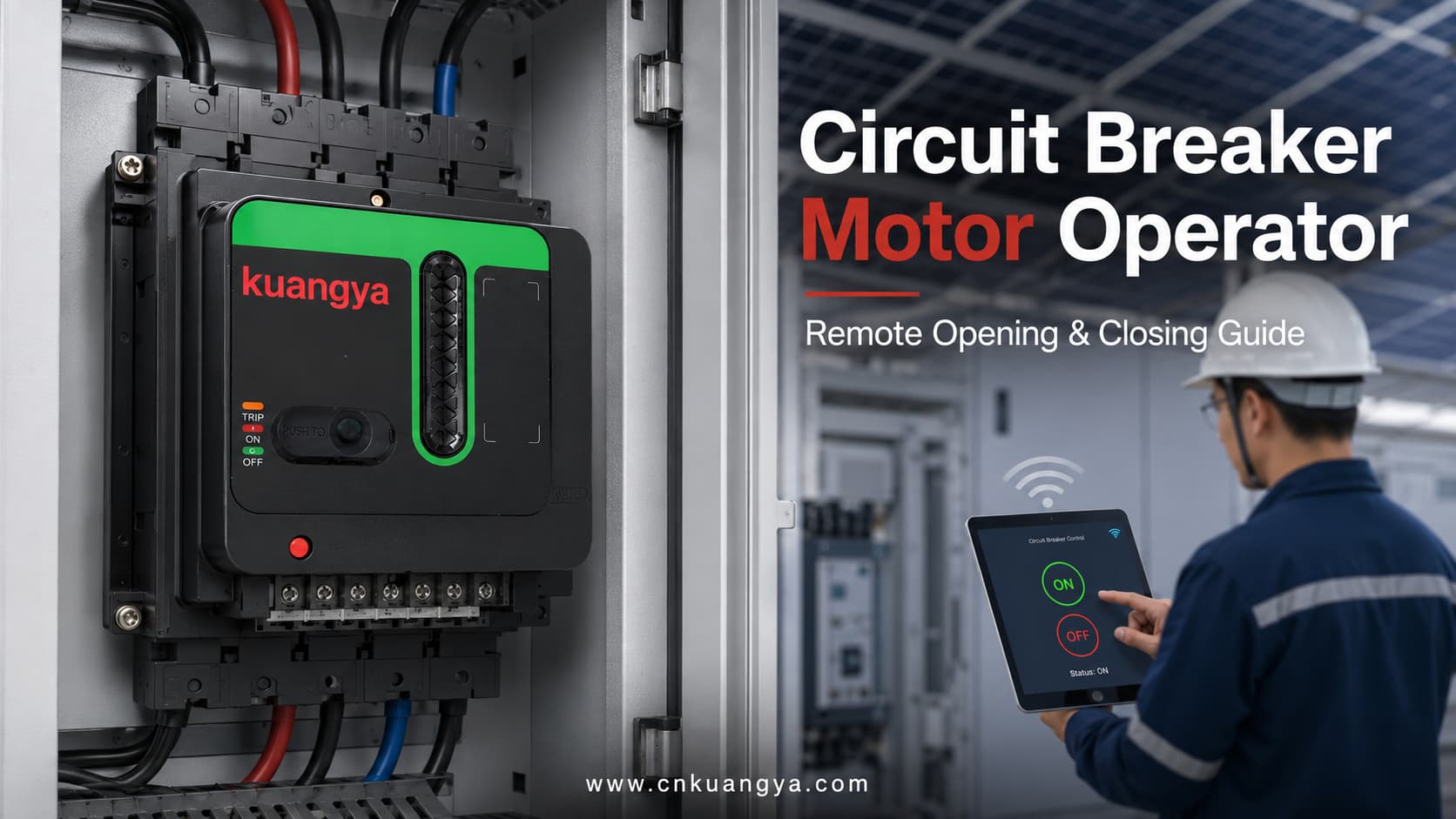
A 차단기용 전동 조작 메커니즘 호환되는 차단기를 기계적으로 작동시키는 전동식 액세서리입니다.
전기적 명령을 수신하면 모터 조작기가 차단기 메커니즘을 이동시켜 원격 개방 또는 투입을 수행합니다. 차단기, 모터 조작기 및 제어 구성에 따라 리셋, 현장 수동 조작, 상태 표시 및 지능형 제어 시스템과의 통합을 지원할 수도 있습니다.
모터 조작기는 차단기의 전기적 보호 기능을 대체하지 않습니다. 차단기는 여전히 과부하, 단락 또는 기타 해당 보호 기능을 제공하며, 모터 조작기는 이를 원격으로 조작할 수 있는 수단을 제공합니다.
주요 차단기 제조사의 모터 메커니즘은 일반적으로 원격 개폐, 배전 자동화, 상용 및 비상 전원 절체, 부하 관리 애플리케이션에 사용됩니다.
| 항목 | 설명 |
|---|---|
| 주요 제품명 | 배선용 차단기용 전동 조작 장치 |
| 기타 통칭 | 차단기 모터 조작기, MCCB 모터 조작기, 전동 조작 기구 |
| 주요 용도 | 전기적 신호를 통해 호환되는 차단기를 조작하기 위함 |
| 주요 기능 | 원격 개방 및 원격 투입 |
| 추가 기능 | 구성에 따른 리셋, 현장 조작 및 상태 표시 |
| 설치 방식 | 호환 차단기의 전면, 측면 또는 장착 구조물에 설치 |
| 공통 제어 소스 | 푸시 버튼, 릴레이, PLC, SCADA, ATS 컨트롤러 또는 모니터링 시스템 |
| 주요 적용 분야 | 태양광(PV) 분전반, 산업용 패널, 절체 시스템 및 무인 현장 |
| 주회로 보호 | 회로 차단기에 의해 제공됨 |
| 제어 전원 | 일반적으로 별도의 AC 또는 DC 보조 전원이 필요함 |
| 호환성 | 차단기 모델, 크기 및 핸들 작동 방식에 맞춰 확인해야 함 |
| 수동 조작 | 많은 설계에서 지원되지만, 방식은 제품마다 다름 |
기존의 회로 차단기는 일반적으로 수동으로 조작됩니다. 기술자가 전기 캐비닛 앞에 서서 차단기 핸들을 ON, OFF 또는 리셋 위치로 조작해야 합니다.
이 방식은 접근이 용이하고 스위칭 작업이 거의 필요 없는 소형 배전반에 실용적입니다. 그러나 전기 설비가 대규모 공장에 분산되어 있거나 원격 및 무인 현장에 설치된 경우 수동 조작의 효율성이 떨어집니다.
예를 들면 다음과 같습니다:
이러한 프로젝트에서는 간단한 스위칭 작업이라도 담당자가 배전반 위치를 파악하고, 현장으로 이동하여, 출입 허가를 받은 뒤 차단기를 수동으로 조작해야 할 수 있습니다.
전동 조작 장치를 사용하면 호환되는 차단기가 원격 제어 패널이나 자동화 시스템으로부터 전기적 명령을 받을 수 있습니다. 이는 선택된 스위칭 작업을 중앙 집중화하고 반복적인 수동 개입을 줄이는 데 도움이 됩니다.
| 비교 항목 | 수동 차단기 조작 | 전동 차단기 조작 |
|---|---|---|
| 작동 위치 | 차단기 바로 앞 | 현장 또는 원격 제어 지점에서 |
| 필요 인원 | 기술자가 캐비닛에 접근해야 함 | 특정 작업은 원격으로 완료 가능 |
| 제어 방식 | 기계식 핸들 조작 | 전기적 명령 및 기계적 조작 |
| PLC 통합 | 일반적으로 액세서리 없이는 사용 불가 | 적절한 제어 배선으로 가능 |
| 중앙 집중식 제어 | 제한적 | 중앙 집중식 전기 제어에 적합 |
| 위치 피드백 | 육안 검사 | 전기적 피드백 추가 가능 |
| 적합한 프로젝트 | 소형 및 접근이 용이한 시스템 | 대규모, 원격 또는 자동화된 설비 |
| 수동 백업 | 표준 | 메커니즘 설계에 따라 유지되는 경우가 많음 |
| 설치 복잡성 | Lower | 기계적 정합 및 제어 배선 필요 |
| 초기 비용 | Lower | 더 높지만, 반복적인 현장 개입을 줄일 수 있음 |
원격 조작이 자격을 갖춘 인력, 전기적 인터록 또는 안전한 유지보수 절차의 필요성을 없애지는 않습니다. 이는 차단기가 작동 명령을 수신하고 수행하는 방식만 변경할 뿐입니다.
전동 조작 장치는 배선용 차단기 전동 조작기라고도 하며,, 호환 가능한 차단기에 설치되거나 연결됩니다.
그 목적은 전기적 제어 명령을 제어된 기계적 움직임으로 변환하는 것입니다.
배선용 차단기에 일반적으로 사용되는 외부 전동 조작기 유형의 경우, 내부 모터가 기어, 캠 또는 링크 장치를 구동합니다. 이 메커니즘은 차단기 핸들을 지원되는 작동 위치 사이로 이동시킵니다.
상세 구조는 차단기 유형 및 제조사에 따라 다릅니다. 일부 외부 메커니즘은 차단기 핸들을 직접 조작하는 반면, 대형 기중 차단기용 전동 조작기는 투입 스프링을 전기적으로 충전하는 등의 기능을 수행할 수 있습니다. 이러한 이유로 실제 차단기 시스템에 대한 작동 원리와 액세서리 구성을 항상 확인해야 합니다.
| 구성 요소 | 주요 기능 |
|---|---|
| 전기 모터 | 메커니즘 작동에 필요한 힘을 생성 |
| 기어 변속기 | 모터의 회전을 제어된 움직임으로 변환 |
| 캠 또는 링키지 | 차단기 핸들로 움직임을 전달 |
| 장착 구조물 | 조작기를 올바른 위치에 고정 |
| 제어 단자 | 전원 및 개폐 명령 수신 |
| 리미트 스위치 | 목표 위치 도달 시 모터 정지 |
| 위치 표시기 | 메커니즘의 작동 상태 표시 |
| 수동 조작 장치 | 필요 시 현장 조작 가능 |
| 로컬/원격 선택기 | 작동 명령의 허용된 소스 변경 |
| 보조 연락처 | 포함된 경우 ON, OFF 또는 TRIP 피드백 제공 |
| 보호 커버 | 가동 부품과의 우발적인 접촉 감소 |
| 인터록 인터페이스 | 다른 차단기 또는 제어기와의 작동 조정 지원 |
모든 모터 조작기가 위에 나열된 모든 구성 요소를 포함하는 것은 아닙니다. 실제 구조는 제품 설계 및 요구 기능에 따라 다릅니다.
일반적인 전동 조작 시퀀스는 5단계로 구성됩니다.
작동 명령은 다음에서 올 수 있습니다:
해당 명령은 일반적으로 차단기를 개방하거나 투입하도록 메커니즘에 지시합니다.
명령이 수신되면 보조 제어 전원을 통해 내부 모터에 전력이 공급됩니다.
제어 전압은 모터 조작기의 정격 전압과 일치해야 합니다. 차단기의 주회로 전압과 조작기의 보조 제어 전압은 별도의 사양입니다.
모터가 내부 기어, 캠 또는 링키지를 구동합니다.
이는 모터의 회전 운동을 차단기 핸들을 조작하는 데 필요한 기계적 움직임으로 변환합니다.
조작 기구는 차단기를 필요한 ON 또는 OFF 위치로 이동시킵니다.
목표 위치에 도달하면 리미트 스위치나 내부 위치 제어 부품이 모터를 정지시킵니다. 이는 동작 완료 후 모터에 계속해서 힘이 가해지는 것을 방지합니다.
적절한 보조 접점이 설치된 경우, 차단기나 모터 조작기는 제어 시스템으로 피드백 신호를 보낼 수 있습니다.
통신형 차단기 시스템은 개방, 투입 및 복귀 명령을 수신할 수 있으며 OFF, ON 및 트립 상태와 같은 정보를 전송할 수 있습니다. 사용 가능한 피드백 기능은 차단기 및 제어 모듈에 따라 다릅니다.
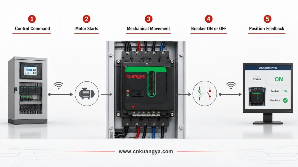
| 단계 | 제어 시스템 동작 | 모터 조작기 동작 | 차단기 상태 |
|---|---|---|---|
| 1 | 개방 또는 투입 명령 전송 | 제어 신호 수신 | 이전 위치 유지 |
| 2 | 필요한 제어 전압 공급 | 내부 모터가 시작됨 | 위치 변경 시작 |
| 3 | 필요한 작동 신호 유지 | 기어 및 링키지가 움직임을 전달 | 핸들이 목표 위치를 향해 이동 |
| 4 | 작동 과정 모니터링 | 리미트 제어가 모터를 정지시킴 | ON 또는 OFF 상태 도달 |
| 5 | 보조 접점 신호를 수신합니다 | 위치 표시를 반환하거나 지원합니다 | Final position is confirmed |
| 6 | Records the result if connected to a monitoring system | Returns to standby condition | Ready for the next permitted operation |
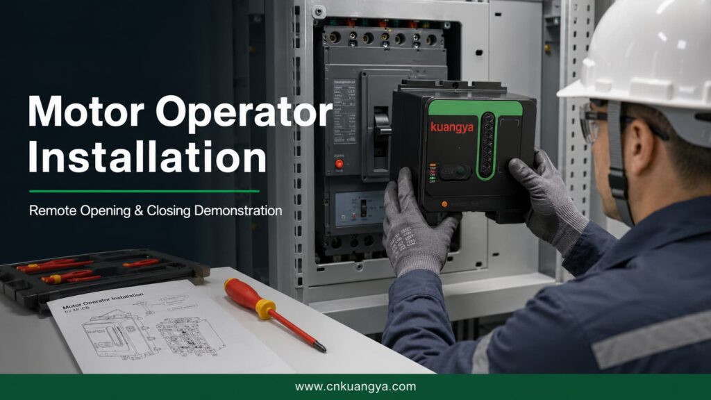
The following video demonstrates the complete installation of a universal motor operator designed for compatible circuit breakers.
It shows how the operating mechanism is positioned and connected to the circuit breaker, followed by a demonstration of remote opening and closing.
This type of motor operator can be used in photovoltaic power distribution cabinets, industrial control panels and intelligent electrical control projects.
| Demonstration Stage | What the Viewer Can See |
|---|---|
| Product preparation | The motor operator and circuit breaker before installation |
| Mounting-position confirmation | The operator is aligned with the circuit breaker |
| Mechanical installation | The motor operator is secured in the required position |
| Handle connection | The operating linkage is connected to the breaker handle |
| Installation adjustment | The mechanism is checked for correct travel and alignment |
| Remote opening | The motor operator moves the breaker from ON to OFF |
| Remote closing | The motor operator moves the breaker from OFF to ON |
| Operation confirmation | The breaker completes the required mechanical movement |
| Final inspection | The installed mechanism is checked for stable operation |
Correct alignment is essential. If the mechanism is installed in the wrong position, the breaker may not complete its full opening, closing or reset movement.
The exact functions of a motor operator for a circuit breaker depend on the breaker model, operating mechanism, wiring arrangement and control system.
The motor operator can move a compatible breaker from its closed position to its open position after receiving an opening command.
Remote opening is useful when a circuit must be isolated from a control room, central panel or monitoring station.
The motor operator can close a compatible breaker after receiving a closing command and after the required system conditions have been satisfied.
Remote closing should be controlled by suitable logic and interlocking. A closing command should not be issued simply because the breaker is open.
After certain trip events, the breaker mechanism must be moved through a reset sequence before it can be closed again.
Some motor operators support resetting, but the method varies considerably. Resetting may be manual, remote or automatic depending on the breaker and control arrangement.
Schneider Electric’s documentation, for example, distinguishes between local reset, remote reset and configurations in which resetting after an electrical-fault trip is restricted unless the system has been specifically configured for it.
Official motor mechanism operating guidance from Schneider Electric shows that a communicating motor mechanism can receive opening, closing and reset commands while transmitting ON, OFF and trip-status information.
Many motor operators retain a local manual operating function.
This may be required during:
The manual operating procedure must follow the instructions for the actual mechanism.
Some mechanisms include a selector that determines whether operation is controlled locally or remotely.
This can help prevent unintended remote commands during maintenance or commissioning.
Position feedback allows a control or monitoring system to determine whether the breaker is:
The available signals depend on the auxiliary contacts and communication modules used in the system.
| 기능 | 설명 | Typical Availability |
|---|---|---|
| Remote opening | Opens the breaker after an electrical command | 공통 |
| Remote closing | Closes the breaker after an electrical command | 공통 |
| Remote reset | Resets a tripped breaker remotely | Model- and configuration-dependent |
| Automatic reset | Resets after a permitted event according to control logic | Model- and system-dependent |
| 수동 조작 | Allows the mechanism to be operated locally | Common on many designs |
| Local/remote selection | Selects the source of operating commands | Model-dependent |
| ON indication | Reports or displays the closed position | Requires appropriate indication |
| OFF indication | Reports or displays the open position | Requires appropriate indication |
| TRIP indication | Reports that the breaker has tripped | Requires trip-status contact |
| PLC 통합 | Accepts commands from an automation controller | Requires compatible control circuit |
| SCADA integration | Supports remote supervisory control | Requires suitable interface equipment |
| Electrical interlocking | Prevents conflicting operating commands | Requires correct system design |
The presence of a motor operator does not automatically mean that every function in this table is available. The actual functions must be confirmed from the product datasheet and wiring diagram.
Motor operators are often confused with other circuit-breaker accessories.
Although these devices can all be connected to a control circuit, they have different purposes.
| Accessory | 주요 목적 | Remote Opening | Remote Closing | 재설정 기능 | Status Feedback |
|---|---|---|---|---|---|
| Motor operator | Mechanically operates the circuit breaker | 예 | 예 | Depending on model | Possible |
| 션트 트립 | Trips or opens the breaker after receiving a voltage signal | 예 | 아니요 | 아니요 | 아니요 |
| Undervoltage release | Opens or prevents closing when its supply voltage is too low | Yes, under specified conditions | 아니요 | 아니요 | 아니요 |
| Closing release | Initiates closing on supported breaker systems | 아니요 | 예 | 아니요 | 아니요 |
| Auxiliary contact | Indicates whether the breaker is open or closed | 아니요 | 아니요 | 아니요 | 예 |
| Alarm contact | Indicates that a protective trip has occurred | 아니요 | 아니요 | 아니요 | 예 |
| Trip-indication contact | Reports a trip caused by a specified condition | 아니요 | 아니요 | 아니요 | 예 |
A shunt trip is designed to open a circuit breaker when its coil receives the specified voltage. It does not normally close or mechanically reset the breaker.
An undervoltage release responds when its control voltage falls below the required operating range. Depending on the product, it can open the breaker or prevent it from closing.
An auxiliary switch provides remote electrical indication of whether the breaker is open or closed. It reports status but does not operate the breaker.
Eaton documentation similarly distinguishes a motor operator, which supports electrical operation, from a shunt trip that opens the breaker and an auxiliary switch that provides remote position indication.
| Project Requirement | More Relevant Accessory |
|---|---|
| Remotely open the breaker only | Shunt trip may be sufficient |
| Remotely open and close the breaker | Motor operator or breaker-specific electrical operating system |
| Prevent closing when control voltage is lost | Undervoltage release |
| Report ON and OFF positions | Auxiliary contact |
| Report an electrical-fault trip | Alarm or trip-indication contact |
| Reset and reclose a supported breaker remotely | Compatible motor operator plus appropriate control logic |
| Transfer between two power sources | Motor operators, controllers and interlocking may be required |
| Integrate the breaker into PLC control | Motor operator plus status and control interfaces |
A motorized operating mechanism can be used wherever a compatible circuit breaker needs to be operated remotely or integrated into an automated electrical-control system.
| 애플리케이션 | Why the Motor Operator Is Used | Typical Control Source |
|---|---|---|
| Photovoltaic distribution cabinet | Supports remote switching and centralized PV-system control | PLC or solar monitoring system |
| Industrial control panel | Reduces repeated manual operation across multiple cabinets | PLC or control relay |
| Automatic transfer system | Coordinates switching between normal and backup sources | ATS controller |
| Generator distribution system | Controls selected breakers during generator operation | Generator controller |
| Energy storage system | Supports remote isolation and auxiliary-circuit control | EMS or PLC |
| Telecommunications site | Allows operation at remote or unattended facilities | Remote monitoring system |
| Intelligent building | Integrates breaker operation into centralized building control | BMS |
| Water treatment facility | Supports automated control of distributed electrical equipment | PLC or SCADA |
| Mining or remote infrastructure | Reduces the need for personnel to access distant cabinets | Remote control panel |
| Agricultural power system | Supports centralized operation across distributed equipment | PLC or relay control |
| Data center auxiliary distribution | Supports coordinated switching of selected non-critical circuits | Power-management system |
| Manufacturing production line | Allows circuit operation as part of an automated sequence | PLC |
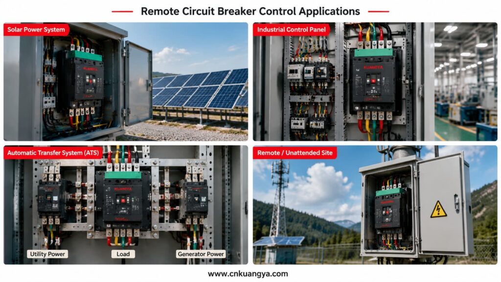
Photovoltaic installations can contain inverters, distribution cabinets, monitoring equipment and auxiliary electrical systems across large areas.
When a breaker must be operated manually, technicians may need to travel to the cabinet even when the required action is relatively simple.
Remote breaker operation should be considered as one part of a coordinated solar PV electrical protection system, together with overcurrent protection, surge protection, electrical isolation and power distribution equipment.
A compatible motor operator can allow selected opening or closing commands to be issued from a monitoring station or control system.
Possible applications include:
For projects that integrate circuit breakers, fuses, SPDs and isolation devices inside one enclosure, explore our PV 결합함 솔루션 for residential, commercial and remote solar installations.
However, remote operation must not be confused with unrestricted automatic reclosing.
If a breaker has tripped because of a short circuit, overload, insulation failure or equipment damage, the cause should be identified before the circuit is energized again.
Circuit-breaker manufacturers specifically warn against reclosing after an electrical fault without first inspecting and repairing the downstream equipment when necessary.
Factories often contain numerous electrical panels serving production lines, pumps, ventilation systems, conveyors and other equipment.
A circuit breaker motor operator can allow selected circuits to be controlled from:
The motor operator can form part of a larger sequence. For example, the system may open a breaker before equipment maintenance or close a breaker only after other safety conditions have been confirmed.
Remote operation should be coordinated with:
Automatic transfer systems switch a load between two power sources, such as:
Motor-operated breakers may be used as the switching devices in these systems.
A suitable controller sends opening and closing commands according to source availability and system conditions.
The system must normally include interlocking to prevent two incompatible sources from being connected at the same time.
| Sequence | Source A Breaker | Source B Breaker | Controller Action |
|---|---|---|---|
| 1 | Closed | Open | Monitors Source A |
| 2 | Opens after Source A failure | Remains open | Confirms Source A breaker is open |
| 3 | Open | Closes | Transfers load to Source B |
| 4 | Remains open | Closed | Monitors source recovery |
| 5 | Open | Opens | Prepares transfer back |
| 6 | Closes | Open | Restores supply from Source A |
Motor-operated breakers are also commonly used in automatic transfer switch solutions to coordinate switching between normal, standby and generator power sources.
This is only a simplified example. An actual transfer system requires project-specific timing, protection, interlocking and control logic.
The term universal motor operator is often used for an adjustable mechanism designed to work with several compatible breaker dimensions or frame sizes.
However, “universal” should not be interpreted as “suitable for every circuit breaker.”
Circuit breakers from different manufacturers and product series can have different:
A universal design may provide adjustable mounting positions, but compatibility still needs to be checked.
A safer technical description is:
A universal motor operator designed for a range of compatible circuit breakers.
| Compatibility Factor | Why It Must Be Confirmed |
|---|---|
| Breaker brand | Different manufacturers use different mechanical designs |
| Complete breaker model | Identifies the specific series and construction |
| 프레임 크기 | Affects breaker dimensions and operating force |
| Handle position | Must align with the operator mechanism |
| Handle dimensions | Must fit the operating interface correctly |
| Handle travel | The operator must complete the full ON and OFF movement |
| Reset movement | The mechanism must support the required trip-reset sequence |
| Mounting holes | Determine whether the operator can be securely installed |
| Breaker depth | Affects the installation and alignment position |
| 폴 수 | May affect overall breaker construction |
| Front accessories | Covers or rotary handles may interfere with installation |
| Required torque | The operator must provide sufficient operating force |
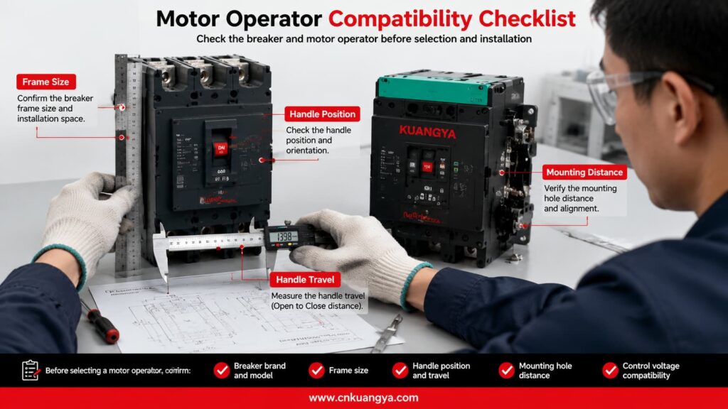
The supplier should receive clear photographs and dimensional information before confirming that a universal motor operator is suitable.
Selecting the correct motorized operating mechanism requires more than knowing the breaker’s rated current.
A 250 A or 400 A description alone is normally insufficient because breakers with the same rated current can have different frame sizes, dimensions and operating mechanisms.
The complete breaker model is one of the most important pieces of information.
Provide:
A nameplate photograph is highly recommended.
The frame size influences:
The breaker’s rated current and frame size are related but are not always identical.
Before selecting the operating mechanism, engineers must first confirm the breaker voltage, rated current, frame size, breaking capacity and accessory requirements. Read our DC MCCB selection guide for a more detailed explanation.
The motor operator normally requires a separate auxiliary power supply.
The buyer must specify:
Writing only “220 V” is incomplete. It should be written as 220 VAC 또는 220 VDC.
The buyer should state whether the project requires:
The supplier needs to know whether commands will come from:
Remote systems should not rely only on sending commands.
Feedback may be required for:
Provide information about:
| Selection Item | Information Required from Buyer | 중요한 이유 |
|---|---|---|
| Breaker brand | Manufacturer name | Identifies the basic mechanical design |
| Complete model | Full breaker model number | Confirms the exact breaker series |
| 프레임 크기 | Breaker frame specification | Determines dimensions and operating force |
| 정격 전류 | Breaker current rating | Helps confirm the breaker configuration |
| 폴 수 | 2P, 3P or 4P | Helps identify the physical version |
| Front photograph | Clear image of the breaker handle and cover | Supports mechanical compatibility checking |
| Side photograph | Clear side view | Helps check depth and mounting arrangement |
| Nameplate photograph | Full readable nameplate | Confirms electrical and model information |
| Control voltage | Voltage value plus AC or DC | Must match the auxiliary power supply |
| Required functions | Opening, closing, reset and manual operation | Determines the mechanism configuration |
| Control source | Button, relay, PLC, SCADA or ATS | Determines wiring and signal requirements |
| Feedback requirement | ON, OFF or TRIP signals | Determines auxiliary contact requirements |
| 애플리케이션 | PV, industrial, ATS or other use | Helps evaluate the operating requirements |
| 수량 | Number of units | Required for quotation and production planning |
| Certification requirement | Required market or project documentation | Determines applicable product and document needs |
The circuit breaker used with a motorized operating mechanism should comply with the applicable low-voltage circuit breaker standards. IEC 60947-2 specifies requirements for industrial and similar low-voltage circuit breakers. The compatibility, control voltage and installation requirements of the motor operator must also be confirmed separately.
Different motor-operator models may be manufactured for different AC or DC control supplies.
The following table provides general examples only. It is not a fixed KUANGYA product-voltage list.
| Example Control Supply | 현재 유형 | Common Control Environment |
|---|---|---|
| 24 VDC | Direct current | PLC and automation systems |
| 48 VDC | Direct current | Telecommunications and industrial control |
| 110 VDC | Direct current | Utility and substation control systems |
| 220 VDC | Direct current | Specialized industrial control systems |
| 110 VAC | Alternating current | Industrial distribution equipment |
| 220 VAC | Alternating current | General control panels |
| 230 VAC | Alternating current | International low-voltage systems |
The available operating range, inrush current, power consumption and command duration must be confirmed from the datasheet for the selected model.
Installation should be carried out by qualified personnel according to the product wiring diagram, breaker instructions and local electrical requirements.
Installers can also refer to this official motor operator installation instruction for an example of mechanical mounting, control wiring and remote opening, closing and resetting procedures.
Before installation:
After installation:
Motor-mechanism wiring should not be changed casually. Manufacturer documentation warns that incorrect modifications can create repeated closing on an electrical fault and requires the mechanism to be wired according to its specified diagram.
| 점검 항목 | Before Installation | After Installation |
|---|---|---|
| Breaker compatibility confirmed | ✓ | - |
| Breaker model recorded | ✓ | - |
| Control voltage verified | ✓ | - |
| Main circuit isolated | ✓ | - |
| Control circuit isolated | ✓ | - |
| Wiring diagram reviewed | ✓ | - |
| Mounting position aligned | ✓ | ✓ |
| Mechanical linkage secured | - | ✓ |
| Full opening movement completed | - | ✓ |
| Full closing movement completed | - | ✓ |
| Reset sequence tested when applicable | - | ✓ |
| Manual operation tested | - | ✓ |
| Remote opening tested | - | ✓ |
| Remote closing tested | - | ✓ |
| Position feedback tested | - | ✓ |
| Interlocking tested | - | ✓ |
| Abnormal noise checked | - | ✓ |
| Mechanical resistance checked | - | ✓ |
Some breaker and motor-operator configurations can support reset and remote reclosing.
However, the fact that a breaker can be closed remotely does not mean that immediate reclosing is safe.
A circuit breaker may trip because of:
Before resetting and closing the breaker, the system or responsible personnel should determine whether the fault has been cleared.
For critical applications, the control logic may include:
After an electrical-fault trip, some manufacturer configurations require local reset by default, while remote reset must be specifically enabled through the relevant communication and control system.
| 확인 | Question Before Reclosing |
|---|---|
| Trip cause | Has the reason for the trip been identified? |
| Fault condition | Has the short circuit, overload or equipment fault been cleared? |
| Downstream circuit | Has the connected equipment been inspected when necessary? |
| Breaker condition | Is the breaker mechanically ready to reset and close? |
| Voltage condition | Is the source voltage within the permitted range? |
| Interlocking | Are all interlocking conditions satisfied? |
| 위치 피드백 | Is the breaker’s actual position confirmed? |
| Number of attempts | Has the system exceeded the permitted reclosing attempts? |
| Personnel safety | Are personnel clear of the affected equipment? |
| Authorization | Has the required automatic or manual permission been received? |
Troubleshooting should begin only after the main and control circuits have been made safe.
The following table lists possible causes. It does not replace the actual product manual or electrical testing.
| 문제 | 가능한 원인 | 권장 확인 |
|---|---|---|
| Motor does not operate | No auxiliary power | Measure and confirm the control supply |
| Motor does not operate | Incorrect terminal wiring | Compare the wiring with the product diagram |
| Breaker does not fully close | Operator is not correctly aligned | Check the mounting and handle position |
| Breaker does not fully open | Linkage is blocked | Inspect the mechanical transmission |
| Motor continues running | Limit-switch or position-control problem | Stop operation and inspect the control mechanism |
| Breaker stops between positions | Insufficient travel or mechanical resistance | Check adjustment and breaker compatibility |
| Remote operation is intermittent | Loose terminal or unstable signal | Inspect terminals, relay output and control voltage |
| Position feedback is incorrect | Auxiliary contact wired incorrectly | Verify the contact type and wiring |
| Manual operation is difficult | Mechanical interference | Isolate power and inspect the installation |
| Reset cannot be completed | Reset travel is insufficient | Check the required breaker reset movement |
| Breaker trips again after closing | Electrical fault remains | Stop reclosing and inspect the downstream circuit |
| Operator makes abnormal noise | Gear or linkage is obstructed | Stop operation and inspect the mechanism |
| PLC sends a command but nothing happens | Signal type is incompatible | Confirm pulse, maintained contact and interface requirements |
| Opening works but closing does not | Closing permission or interlocking is absent | Check ready-to-close and interlocking conditions |
아니요.
The circuit breaker provides electrical protection and circuit switching. The motor operator is an accessory that operates a compatible breaker through electrical commands.
Yes, compatible motor mechanisms can provide remote opening and closing. The exact operation depends on the breaker, motor operator, control voltage and wiring configuration.
아니요.
A universal motor operator may be adjustable for several compatible breaker sizes, but the breaker model, handle position, travel distance, mounting dimensions and required operating force must still be checked.
Some models and configurations support reset operation.
The reset may be manual, remote or automatic. Resetting after an electrical-fault trip may be restricted by the breaker system and control configuration.
아니요.
The overload and short-circuit protection functions are provided by the circuit breaker and its trip unit.
아니요.
A shunt trip is primarily used to open the breaker after receiving an electrical signal. A motor operator may mechanically open and close a compatible breaker.
Many motor operators retain a manual operating method, but the exact procedure depends on the product design.
Yes, when the control voltage, signal type, wiring and interface are compatible with the PLC system.
A relay interface may be required depending on the PLC output and motor-operator control circuit.
아니요.
The cause of a protective trip should be identified before the circuit is energized again. Repeated closing on an unresolved fault can cause equipment damage and create safety risks.
Send the breaker brand, complete model, frame size, pole number, control voltage, required functions, quantity and clear photographs.
Customers can copy the following format when requesting a quotation:
Product required:
Motorized operating mechanism for circuit breaker

Circuit breaker brand:

Complete circuit breaker model:

Breaker frame size:

Rated current:

Number of poles:

Control voltage:
Please specify AC or DC.

Required functions:
Remote opening / remote closing / reset / manual operation

Control method:
Push button / relay / PLC / SCADA / ATS / other

Position feedback required:
ON / OFF / TRIP / other

Application:
PV distribution cabinet / industrial panel / ATS / other

Installation environment:

Quantity:

Required certificates or documents:

Please provide:
Product datasheet
Wiring diagram
Installation dimensions
Compatibility confirmation
Quotation
Delivery time
Attach the following materials whenever possible:
A 차단기용 전동 조작 메커니즘 converts an electrical command into mechanical breaker operation.
It can enable remote opening, remote closing, local manual operation, centralized control and integration with PLC, SCADA, ATS or intelligent monitoring systems.
Motor operators are particularly useful in:
However, correct selection is essential.
A product described as a universal motor operator is not automatically compatible with every circuit breaker. The breaker model, frame size, handle dimensions, operating travel, control voltage and required functions must all be checked before ordering.
Remote reset and reclosing must also be controlled carefully. A circuit breaker that has tripped because of an electrical fault should not be closed again until the fault condition has been evaluated and cleared.
KUANGYA provides motorized operating mechanisms for circuit breaker control applications, including photovoltaic distribution cabinets and intelligent electrical-control projects.
Send us your circuit breaker model, nameplate photograph, control voltage, required functions and quantity for product matching, technical information and quotation.
Contact KUANGYA for inquiries, model selection and bulk-order quotations.

