Zona industriale di WengYang Yueqing Wenzhou 325000
Orario di lavoro
Da lunedì a venerdì: dalle 7.00 alle 19.00
Fine settimana: 10.00 - 17.00
Zona industriale di WengYang Yueqing Wenzhou 325000
Orario di lavoro
Da lunedì a venerdì: dalle 7.00 alle 19.00
Fine settimana: 10.00 - 17.00

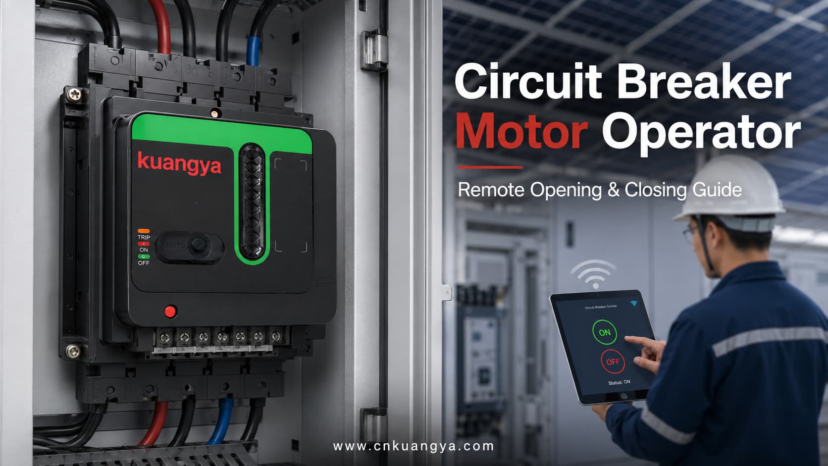
A meccanismo di comando motorizzato per interruttore automatico è un accessorio ad azionamento elettrico che comanda meccanicamente un interruttore automatico compatibile.
Dopo aver ricevuto un comando elettrico, il comando motore aziona il meccanismo dell'interruttore per eseguire l'apertura o la chiusura da remoto. A seconda dell'interruttore, del comando motore e della configurazione di controllo, può supportare anche il riarmo, il comando manuale locale, l'indicazione di stato e l'integrazione con sistemi di controllo intelligenti.
Un comando motore non sostituisce le funzioni di protezione elettrica dell'interruttore. L'interruttore continua a fornire protezione da sovraccarico, cortocircuito o altre protezioni applicabili, mentre il comando motore fornisce un mezzo per azionarlo a distanza.
I meccanismi motorizzati dei principali produttori di interruttori sono comunemente utilizzati per l'apertura e la chiusura a distanza, l'automazione della distribuzione elettrica, il commutatore di sorgente normale/emergenza e le applicazioni di gestione del carico.
| Articolo | Descrizione |
|---|---|
| Nome principale del prodotto | Comando motorizzato per interruttore automatico |
| Altri nomi comuni | Motorizzazione per interruttore, comando a motore per MCCB, meccanismo di comando elettrico |
| Scopo principale | Azionare un interruttore automatico compatibile tramite un comando elettrico |
| Funzioni principali | Apertura remota e chiusura remota |
| Funzioni aggiuntive | Ripristino, comando locale e indicazione di stato, a seconda della configurazione |
| Metodo di installazione | Montaggio frontale, laterale o su struttura di supporto di un interruttore compatibile |
| Fonti di controllo comuni | Pulsante, relè, PLC, SCADA, controllore ATS o sistema di monitoraggio |
| Applicazioni tipiche | Quadri di distribuzione FV, quadri industriali, sistemi di trasferimento e siti non presidiati |
| Protezione del circuito principale | Fornito dall'interruttore automatico |
| Alimentazione di controllo | È normalmente richiesta un'alimentazione ausiliaria separata in CA o CC |
| Compatibilità | Deve essere verificato in base al modello, alla taglia e al movimento della maniglia dell'interruttore |
| Funzionamento manuale | Disponibile su molti modelli, ma il metodo varia a seconda del prodotto |
Gli interruttori automatici tradizionali vengono solitamente azionati manualmente. Un tecnico deve posizionarsi davanti al quadro elettrico e spostare la maniglia dell'interruttore nelle posizioni ON, OFF o di ripristino.
Questo approccio è pratico per piccoli quadri di distribuzione di facile accesso e che richiedono raramente interventi di commutazione. Tuttavia, l'operazione manuale diventa meno efficiente quando le apparecchiature elettriche sono distribuite in un grande stabilimento o installate in siti remoti e non presidiati.
Gli esempi includono:
In questi progetti, anche una semplice operazione di commutazione può richiedere al personale di individuare il quadro, recarsi sul posto, ottenere l'autorizzazione all'accesso e azionare manualmente l'interruttore.
Un comando motorizzato consente a un interruttore compatibile di ricevere un comando elettrico da un pannello di controllo remoto o da un sistema di automazione. Ciò contribuisce a centralizzare le operazioni di commutazione selezionate e riduce i ripetuti interventi manuali.
| Voce di confronto | Funzionamento manuale dell'interruttore | Funzionamento motorizzato dell'interruttore |
|---|---|---|
| Luogo di installazione | Direttamente davanti all'interruttore | Localmente o da un punto di controllo remoto |
| Personale richiesto | Il tecnico deve accedere al quadro | Alcune operazioni possono essere completate da remoto |
| Metodo di controllo | Azionamento tramite maniglia meccanica | Comando elettrico più azionamento meccanico |
| Integrazione PLC | Normalmente non disponibile senza accessori | Possibile con cablaggio di controllo adeguato |
| Controllo centralizzato | Limitato | Adatto per controllo elettrico centralizzato |
| Feedback di posizione | Ispezione visiva | È possibile aggiungere un feedback elettrico |
| Progetti idonei | Sistemi piccoli e facilmente accessibili | Installazioni di grandi dimensioni, remote o automatizzate |
| Backup manuale | Standard | Spesso mantenuto, a seconda del design del meccanismo |
| Complessità di installazione | Più basso | Richiede accoppiamento meccanico e cablaggio di controllo |
| Costo iniziale | Più basso | Più elevato, ma può ridurre i ripetuti interventi in loco |
Il comando a distanza non elimina la necessità di personale qualificato, interblocchi elettrici o procedure di manutenzione sicure. Modifica solo il modo in cui l'interruttore riceve ed esegue un comando operativo.
Un comando motorizzato, chiamato anche motorizzazione per interruttore automatico, viene installato su o collegato a un interruttore automatico compatibile.
Il suo scopo è convertire un comando elettrico in un movimento meccanico controllato.
Per il tipo di comando motorizzato esterno comunemente utilizzato con gli interruttori scatolati (MCCB), il motore interno aziona un ingranaggio, una camma o un leverismo. Questo meccanismo sposta quindi la leva dell'interruttore tra le sue posizioni operative supportate.
La costruzione dettagliata varia a seconda del tipo di interruttore e del produttore. Alcuni meccanismi esterni azionano direttamente la leva dell'interruttore, mentre i comandi motorizzati per interruttori aperti di maggiori dimensioni possono svolgere funzioni come la carica elettrica delle molle di chiusura. Per questo motivo, il principio di funzionamento e la configurazione degli accessori devono essere sempre verificati per lo specifico sistema di interruzione.
| Componente | Funzione principale |
|---|---|
| Motore elettrico | Produce la forza necessaria per azionare il meccanismo |
| Trasmissione a ingranaggi | Converte la rotazione del motore in movimento controllato |
| Camma o leveraggio | Trasferisce il movimento alla leva dell'interruttore |
| Struttura di montaggio | Fissa l'operatore nella posizione corretta |
| Terminali di controllo | Riceve alimentazione e comandi di apertura o chiusura |
| Finecorsa | Arresta il motore quando viene raggiunta la posizione target |
| Indicatore di posizione | Mostra le condizioni operative del meccanismo |
| Dispositivo di comando manuale | Consente il funzionamento locale quando richiesto |
| Selettore locale/remoto | Modifica la sorgente consentita dei comandi operativi |
| Contatti ausiliari | Fornisce feedback di stato ON, OFF o TRIP quando incluso |
| Copertura protettiva | Riduce il contatto accidentale con le parti in movimento |
| Interfaccia di interblocco | Aiuta a coordinare il funzionamento con altri interruttori o controllori |
Non tutti gli operatori motorizzati contengono tutti i componenti sopra elencati. La struttura effettiva dipende dal design del prodotto e dalle funzioni richieste.
Una tipica sequenza operativa motorizzata consiste in cinque fasi.
Il comando operativo può provenire da:
Il comando istruisce normalmente il meccanismo ad aprire o chiudere l'interruttore.
Dopo aver ricevuto il comando, il motore interno viene alimentato dall'alimentazione di controllo ausiliaria.
La tensione di controllo deve corrispondere alla tensione nominale dell'operatore a motore. La tensione del circuito principale dell'interruttore e la tensione di controllo ausiliaria dell'operatore sono specifiche separate.
Il motore aziona gli ingranaggi interni, la camma o il leveraggio.
Questo converte il movimento rotatorio del motore nel movimento meccanico necessario per azionare la maniglia dell'interruttore.
Il meccanismo di manovra sposta l'interruttore verso la posizione ON o OFF richiesta.
Quando viene raggiunta la posizione target, un finecorsa o un componente interno di controllo della posizione arresta il motore. Ciò impedisce al motore di continuare ad applicare forza una volta completata l'operazione.
Quando sono installati contatti ausiliari idonei, l'interruttore o il comando motorizzato può inviare un segnale di feedback al sistema di controllo.
I sistemi di interruttori comunicanti possono ricevere comandi di apertura, chiusura e riarmo e trasmettere stati come OFF, ON e stato di scatto (tripped). Le funzioni di feedback disponibili dipendono dall'interruttore e dal modulo di controllo.
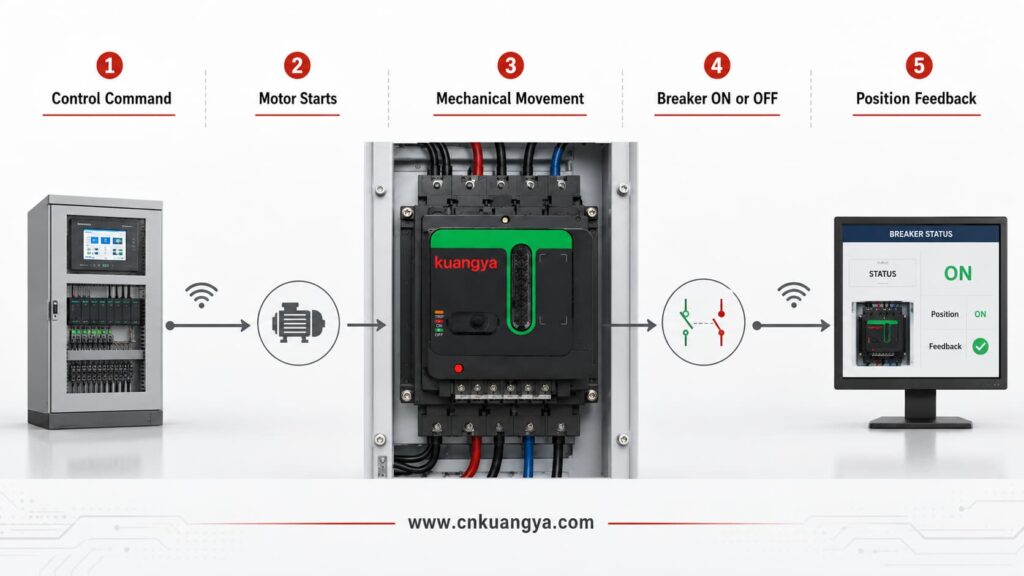
| Passo | Azione del sistema di controllo | Azione dell'operatore a motore | Stato dell'interruttore |
|---|---|---|---|
| 1 | Invia un comando di apertura o chiusura | Riceve il segnale di controllo | Rimane nella sua posizione precedente |
| 2 | Fornisce la tensione di controllo richiesta | Avvio del motore interno | Inizio del cambio di posizione |
| 3 | Mantenimento del segnale operativo richiesto | Trasmissione del movimento tramite ingranaggi e rinvii | Spostamento della maniglia verso la posizione target |
| 4 | Monitoraggio del processo operativo | Arresto del motore tramite controllo di finecorsa | Raggiungimento della posizione ON o OFF |
| 5 | Riceve un segnale di contatto ausiliario | Restituisce o supporta l'indicazione di posizione | Final position is confirmed |
| 6 | Records the result if connected to a monitoring system | Returns to standby condition | Ready for the next permitted operation |
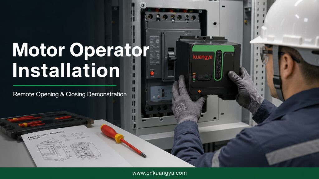
The following video demonstrates the complete installation of a universal motor operator designed for compatible circuit breakers.
It shows how the operating mechanism is positioned and connected to the circuit breaker, followed by a demonstration of remote opening and closing.
This type of motor operator can be used in photovoltaic power distribution cabinets, industrial control panels and intelligent electrical control projects.
| Demonstration Stage | What the Viewer Can See |
|---|---|
| Product preparation | The motor operator and circuit breaker before installation |
| Mounting-position confirmation | The operator is aligned with the circuit breaker |
| Mechanical installation | The motor operator is secured in the required position |
| Handle connection | The operating linkage is connected to the breaker handle |
| Installation adjustment | The mechanism is checked for correct travel and alignment |
| Remote opening | The motor operator moves the breaker from ON to OFF |
| Remote closing | The motor operator moves the breaker from OFF to ON |
| Operation confirmation | The breaker completes the required mechanical movement |
| Final inspection | The installed mechanism is checked for stable operation |
Correct alignment is essential. If the mechanism is installed in the wrong position, the breaker may not complete its full opening, closing or reset movement.
The exact functions of a motor operator for a circuit breaker depend on the breaker model, operating mechanism, wiring arrangement and control system.
The motor operator can move a compatible breaker from its closed position to its open position after receiving an opening command.
Remote opening is useful when a circuit must be isolated from a control room, central panel or monitoring station.
The motor operator can close a compatible breaker after receiving a closing command and after the required system conditions have been satisfied.
Remote closing should be controlled by suitable logic and interlocking. A closing command should not be issued simply because the breaker is open.
After certain trip events, the breaker mechanism must be moved through a reset sequence before it can be closed again.
Some motor operators support resetting, but the method varies considerably. Resetting may be manual, remote or automatic depending on the breaker and control arrangement.
Schneider Electric’s documentation, for example, distinguishes between local reset, remote reset and configurations in which resetting after an electrical-fault trip is restricted unless the system has been specifically configured for it.
Official motor mechanism operating guidance from Schneider Electric shows that a communicating motor mechanism can receive opening, closing and reset commands while transmitting ON, OFF and trip-status information.
Many motor operators retain a local manual operating function.
This may be required during:
The manual operating procedure must follow the instructions for the actual mechanism.
Some mechanisms include a selector that determines whether operation is controlled locally or remotely.
This can help prevent unintended remote commands during maintenance or commissioning.
Position feedback allows a control or monitoring system to determine whether the breaker is:
The available signals depend on the auxiliary contacts and communication modules used in the system.
| Funzione | Descrizione | Typical Availability |
|---|---|---|
| Remote opening | Opens the breaker after an electrical command | Comune |
| Remote closing | Closes the breaker after an electrical command | Comune |
| Remote reset | Resets a tripped breaker remotely | Model- and configuration-dependent |
| Automatic reset | Resets after a permitted event according to control logic | Model- and system-dependent |
| Funzionamento manuale | Allows the mechanism to be operated locally | Common on many designs |
| Local/remote selection | Selects the source of operating commands | Model-dependent |
| ON indication | Reports or displays the closed position | Requires appropriate indication |
| OFF indication | Reports or displays the open position | Requires appropriate indication |
| TRIP indication | Reports that the breaker has tripped | Requires trip-status contact |
| Integrazione PLC | Accepts commands from an automation controller | Requires compatible control circuit |
| SCADA integration | Supports remote supervisory control | Requires suitable interface equipment |
| Electrical interlocking | Prevents conflicting operating commands | Requires correct system design |
The presence of a motor operator does not automatically mean that every function in this table is available. The actual functions must be confirmed from the product datasheet and wiring diagram.
Motor operators are often confused with other circuit-breaker accessories.
Although these devices can all be connected to a control circuit, they have different purposes.
| Accessory | Scopo principale | Remote Opening | Remote Closing | Funzione di reset | Status Feedback |
|---|---|---|---|---|---|
| Motor operator | Mechanically operates the circuit breaker | Sì | Sì | Depending on model | Possible |
| Intervento in derivazione | Trips or opens the breaker after receiving a voltage signal | Sì | No | No | No |
| Undervoltage release | Opens or prevents closing when its supply voltage is too low | Yes, under specified conditions | No | No | No |
| Closing release | Initiates closing on supported breaker systems | No | Sì | No | No |
| Auxiliary contact | Indicates whether the breaker is open or closed | No | No | No | Sì |
| Alarm contact | Indicates that a protective trip has occurred | No | No | No | Sì |
| Trip-indication contact | Reports a trip caused by a specified condition | No | No | No | Sì |
A shunt trip is designed to open a circuit breaker when its coil receives the specified voltage. It does not normally close or mechanically reset the breaker.
Un undervoltage release responds when its control voltage falls below the required operating range. Depending on the product, it can open the breaker or prevent it from closing.
Un auxiliary switch provides remote electrical indication of whether the breaker is open or closed. It reports status but does not operate the breaker.
Eaton documentation similarly distinguishes a motor operator, which supports electrical operation, from a shunt trip that opens the breaker and an auxiliary switch that provides remote position indication.
| Project Requirement | More Relevant Accessory |
|---|---|
| Remotely open the breaker only | Shunt trip may be sufficient |
| Remotely open and close the breaker | Motor operator or breaker-specific electrical operating system |
| Prevent closing when control voltage is lost | Undervoltage release |
| Report ON and OFF positions | Auxiliary contact |
| Report an electrical-fault trip | Alarm or trip-indication contact |
| Reset and reclose a supported breaker remotely | Compatible motor operator plus appropriate control logic |
| Transfer between two power sources | Motor operators, controllers and interlocking may be required |
| Integrate the breaker into PLC control | Motor operator plus status and control interfaces |
A motorized operating mechanism can be used wherever a compatible circuit breaker needs to be operated remotely or integrated into an automated electrical-control system.
| Applicazione | Why the Motor Operator Is Used | Typical Control Source |
|---|---|---|
| Photovoltaic distribution cabinet | Supports remote switching and centralized PV-system control | PLC or solar monitoring system |
| Industrial control panel | Reduces repeated manual operation across multiple cabinets | PLC or control relay |
| Automatic transfer system | Coordinates switching between normal and backup sources | ATS controller |
| Generator distribution system | Controls selected breakers during generator operation | Generator controller |
| Energy storage system | Supports remote isolation and auxiliary-circuit control | EMS or PLC |
| Telecommunications site | Allows operation at remote or unattended facilities | Remote monitoring system |
| Intelligent building | Integrates breaker operation into centralized building control | BMS |
| Water treatment facility | Supports automated control of distributed electrical equipment | PLC or SCADA |
| Mining or remote infrastructure | Reduces the need for personnel to access distant cabinets | Remote control panel |
| Agricultural power system | Supports centralized operation across distributed equipment | PLC or relay control |
| Data center auxiliary distribution | Supports coordinated switching of selected non-critical circuits | Power-management system |
| Manufacturing production line | Allows circuit operation as part of an automated sequence | PLC |
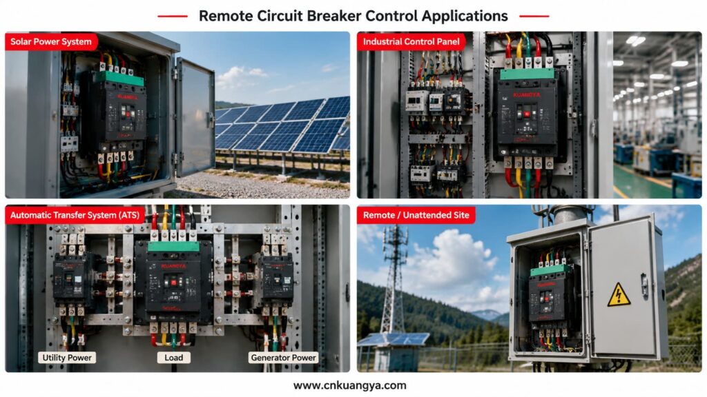
Photovoltaic installations can contain inverters, distribution cabinets, monitoring equipment and auxiliary electrical systems across large areas.
When a breaker must be operated manually, technicians may need to travel to the cabinet even when the required action is relatively simple.
Remote breaker operation should be considered as one part of a coordinated solar PV electrical protection system, together with overcurrent protection, surge protection, electrical isolation and power distribution equipment.
A compatible motor operator can allow selected opening or closing commands to be issued from a monitoring station or control system.
Possible applications include:
For projects that integrate circuit breakers, fuses, SPDs and isolation devices inside one enclosure, explore our Soluzioni di quadri di parallelo fotovoltaici (string box) for residential, commercial and remote solar installations.
However, remote operation must not be confused with unrestricted automatic reclosing.
If a breaker has tripped because of a short circuit, overload, insulation failure or equipment damage, the cause should be identified before the circuit is energized again.
Circuit-breaker manufacturers specifically warn against reclosing after an electrical fault without first inspecting and repairing the downstream equipment when necessary.
Factories often contain numerous electrical panels serving production lines, pumps, ventilation systems, conveyors and other equipment.
A circuit breaker motor operator can allow selected circuits to be controlled from:
The motor operator can form part of a larger sequence. For example, the system may open a breaker before equipment maintenance or close a breaker only after other safety conditions have been confirmed.
Remote operation should be coordinated with:
Automatic transfer systems switch a load between two power sources, such as:
Motor-operated breakers may be used as the switching devices in these systems.
A suitable controller sends opening and closing commands according to source availability and system conditions.
The system must normally include interlocking to prevent two incompatible sources from being connected at the same time.
| Sequence | Source A Breaker | Source B Breaker | Controller Action |
|---|---|---|---|
| 1 | Closed | Open | Monitors Source A |
| 2 | Opens after Source A failure | Remains open | Confirms Source A breaker is open |
| 3 | Open | Closes | Transfers load to Source B |
| 4 | Remains open | Closed | Monitors source recovery |
| 5 | Open | Opens | Prepares transfer back |
| 6 | Closes | Open | Restores supply from Source A |
Motor-operated breakers are also commonly used in automatic transfer switch solutions to coordinate switching between normal, standby and generator power sources.
This is only a simplified example. An actual transfer system requires project-specific timing, protection, interlocking and control logic.
The term universal motor operator is often used for an adjustable mechanism designed to work with several compatible breaker dimensions or frame sizes.
However, “universal” should not be interpreted as “suitable for every circuit breaker.”
Circuit breakers from different manufacturers and product series can have different:
A universal design may provide adjustable mounting positions, but compatibility still needs to be checked.
A safer technical description is:
A universal motor operator designed for a range of compatible circuit breakers.
| Compatibility Factor | Why It Must Be Confirmed |
|---|---|
| Breaker brand | Different manufacturers use different mechanical designs |
| Complete breaker model | Identifies the specific series and construction |
| Dimensioni del telaio | Affects breaker dimensions and operating force |
| Handle position | Must align with the operator mechanism |
| Handle dimensions | Must fit the operating interface correctly |
| Handle travel | The operator must complete the full ON and OFF movement |
| Reset movement | The mechanism must support the required trip-reset sequence |
| Mounting holes | Determine whether the operator can be securely installed |
| Breaker depth | Affects the installation and alignment position |
| Numero di pali | May affect overall breaker construction |
| Front accessories | Covers or rotary handles may interfere with installation |
| Required torque | The operator must provide sufficient operating force |
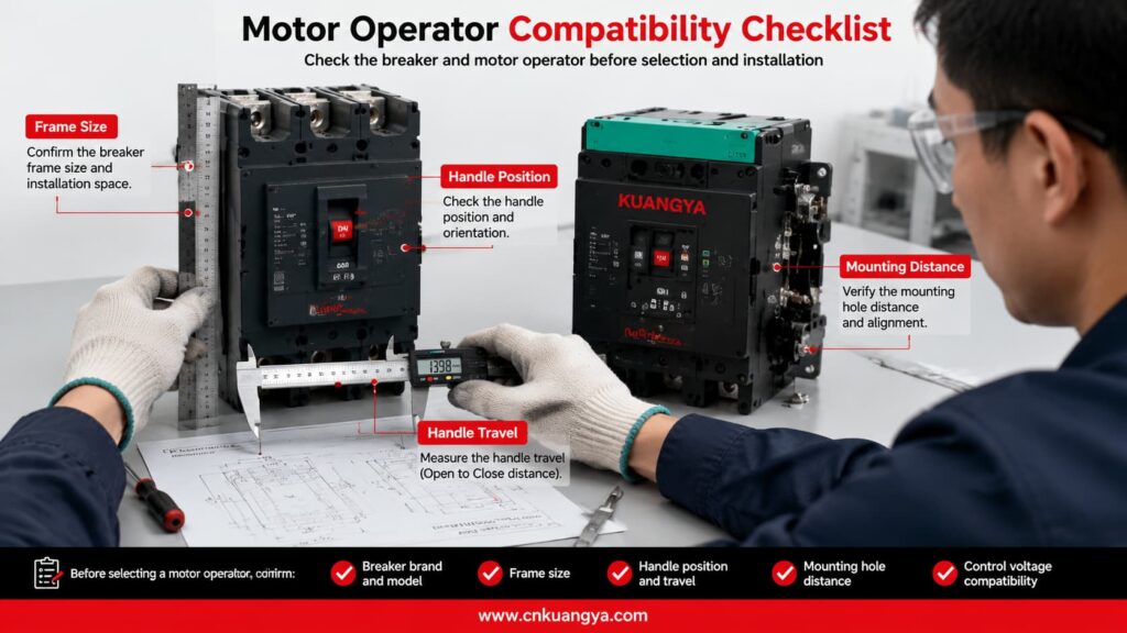
The supplier should receive clear photographs and dimensional information before confirming that a universal motor operator is suitable.
Selecting the correct motorized operating mechanism requires more than knowing the breaker’s rated current.
A 250 A or 400 A description alone is normally insufficient because breakers with the same rated current can have different frame sizes, dimensions and operating mechanisms.
The complete breaker model is one of the most important pieces of information.
Provide:
A nameplate photograph is highly recommended.
The frame size influences:
The breaker’s rated current and frame size are related but are not always identical.
Before selecting the operating mechanism, engineers must first confirm the breaker voltage, rated current, frame size, breaking capacity and accessory requirements. Read our DC MCCB selection guide for a more detailed explanation.
The motor operator normally requires a separate auxiliary power supply.
The buyer must specify:
Writing only “220 V” is incomplete. It should be written as 220 VAC o 220 VDC.
The buyer should state whether the project requires:
The supplier needs to know whether commands will come from:
Remote systems should not rely only on sending commands.
Feedback may be required for:
Provide information about:
| Selection Item | Information Required from Buyer | Perché è importante |
|---|---|---|
| Breaker brand | Manufacturer name | Identifies the basic mechanical design |
| Complete model | Full breaker model number | Confirms the exact breaker series |
| Dimensioni del telaio | Breaker frame specification | Determines dimensions and operating force |
| Corrente nominale | Breaker current rating | Helps confirm the breaker configuration |
| Numero di pali | 2P, 3P or 4P | Helps identify the physical version |
| Front photograph | Clear image of the breaker handle and cover | Supports mechanical compatibility checking |
| Side photograph | Clear side view | Helps check depth and mounting arrangement |
| Nameplate photograph | Full readable nameplate | Confirms electrical and model information |
| Control voltage | Voltage value plus AC or DC | Must match the auxiliary power supply |
| Required functions | Opening, closing, reset and manual operation | Determines the mechanism configuration |
| Control source | Button, relay, PLC, SCADA or ATS | Determines wiring and signal requirements |
| Feedback requirement | ON, OFF or TRIP signals | Determines auxiliary contact requirements |
| Applicazione | PV, industrial, ATS or other use | Helps evaluate the operating requirements |
| Quantità | Number of units | Required for quotation and production planning |
| Certification requirement | Required market or project documentation | Determines applicable product and document needs |
The circuit breaker used with a motorized operating mechanism should comply with the applicable low-voltage circuit breaker standards. IEC 60947-2 specifies requirements for industrial and similar low-voltage circuit breakers. The compatibility, control voltage and installation requirements of the motor operator must also be confirmed separately.
Different motor-operator models may be manufactured for different AC or DC control supplies.
The following table provides general examples only. It is not a fixed KUANGYA product-voltage list.
| Example Control Supply | Tipo attuale | Common Control Environment |
|---|---|---|
| 24 VDC | Direct current | PLC and automation systems |
| 48 VDC | Direct current | Telecommunications and industrial control |
| 110 VDC | Direct current | Utility and substation control systems |
| 220 VDC | Direct current | Specialized industrial control systems |
| 110 VAC | Alternating current | Industrial distribution equipment |
| 220 VAC | Alternating current | General control panels |
| 230 VAC | Alternating current | International low-voltage systems |
The available operating range, inrush current, power consumption and command duration must be confirmed from the datasheet for the selected model.
Installation should be carried out by qualified personnel according to the product wiring diagram, breaker instructions and local electrical requirements.
Installers can also refer to this official motor operator installation instruction for an example of mechanical mounting, control wiring and remote opening, closing and resetting procedures.
Before installation:
After installation:
Motor-mechanism wiring should not be changed casually. Manufacturer documentation warns that incorrect modifications can create repeated closing on an electrical fault and requires the mechanism to be wired according to its specified diagram.
| Voce di ispezione | Before Installation | After Installation |
|---|---|---|
| Breaker compatibility confirmed | ✓ | - |
| Breaker model recorded | ✓ | - |
| Control voltage verified | ✓ | - |
| Main circuit isolated | ✓ | - |
| Control circuit isolated | ✓ | - |
| Wiring diagram reviewed | ✓ | - |
| Mounting position aligned | ✓ | ✓ |
| Mechanical linkage secured | - | ✓ |
| Full opening movement completed | - | ✓ |
| Full closing movement completed | - | ✓ |
| Reset sequence tested when applicable | - | ✓ |
| Manual operation tested | - | ✓ |
| Remote opening tested | - | ✓ |
| Remote closing tested | - | ✓ |
| Position feedback tested | - | ✓ |
| Interlocking tested | - | ✓ |
| Abnormal noise checked | - | ✓ |
| Mechanical resistance checked | - | ✓ |
Some breaker and motor-operator configurations can support reset and remote reclosing.
However, the fact that a breaker can be closed remotely does not mean that immediate reclosing is safe.
A circuit breaker may trip because of:
Before resetting and closing the breaker, the system or responsible personnel should determine whether the fault has been cleared.
For critical applications, the control logic may include:
After an electrical-fault trip, some manufacturer configurations require local reset by default, while remote reset must be specifically enabled through the relevant communication and control system.
| Controllo | Question Before Reclosing |
|---|---|
| Trip cause | Has the reason for the trip been identified? |
| Fault condition | Has the short circuit, overload or equipment fault been cleared? |
| Downstream circuit | Has the connected equipment been inspected when necessary? |
| Breaker condition | Is the breaker mechanically ready to reset and close? |
| Voltage condition | Is the source voltage within the permitted range? |
| Interlocking | Are all interlocking conditions satisfied? |
| Feedback di posizione | Is the breaker’s actual position confirmed? |
| Number of attempts | Has the system exceeded the permitted reclosing attempts? |
| Personnel safety | Are personnel clear of the affected equipment? |
| Authorization | Has the required automatic or manual permission been received? |
Troubleshooting should begin only after the main and control circuits have been made safe.
The following table lists possible causes. It does not replace the actual product manual or electrical testing.
| Problema | Possibile causa | Controllo consigliato |
|---|---|---|
| Motor does not operate | No auxiliary power | Measure and confirm the control supply |
| Motor does not operate | Incorrect terminal wiring | Compare the wiring with the product diagram |
| Breaker does not fully close | Operator is not correctly aligned | Check the mounting and handle position |
| Breaker does not fully open | Linkage is blocked | Inspect the mechanical transmission |
| Motor continues running | Limit-switch or position-control problem | Stop operation and inspect the control mechanism |
| Breaker stops between positions | Insufficient travel or mechanical resistance | Check adjustment and breaker compatibility |
| Remote operation is intermittent | Loose terminal or unstable signal | Inspect terminals, relay output and control voltage |
| Position feedback is incorrect | Auxiliary contact wired incorrectly | Verify the contact type and wiring |
| Manual operation is difficult | Mechanical interference | Isolate power and inspect the installation |
| Reset cannot be completed | Reset travel is insufficient | Check the required breaker reset movement |
| Breaker trips again after closing | Electrical fault remains | Stop reclosing and inspect the downstream circuit |
| Operator makes abnormal noise | Gear or linkage is obstructed | Stop operation and inspect the mechanism |
| PLC sends a command but nothing happens | Signal type is incompatible | Confirm pulse, maintained contact and interface requirements |
| Opening works but closing does not | Closing permission or interlocking is absent | Check ready-to-close and interlocking conditions |
No.
The circuit breaker provides electrical protection and circuit switching. The motor operator is an accessory that operates a compatible breaker through electrical commands.
Yes, compatible motor mechanisms can provide remote opening and closing. The exact operation depends on the breaker, motor operator, control voltage and wiring configuration.
No.
A universal motor operator may be adjustable for several compatible breaker sizes, but the breaker model, handle position, travel distance, mounting dimensions and required operating force must still be checked.
Some models and configurations support reset operation.
The reset may be manual, remote or automatic. Resetting after an electrical-fault trip may be restricted by the breaker system and control configuration.
No.
The overload and short-circuit protection functions are provided by the circuit breaker and its trip unit.
No.
A shunt trip is primarily used to open the breaker after receiving an electrical signal. A motor operator may mechanically open and close a compatible breaker.
Many motor operators retain a manual operating method, but the exact procedure depends on the product design.
Yes, when the control voltage, signal type, wiring and interface are compatible with the PLC system.
A relay interface may be required depending on the PLC output and motor-operator control circuit.
No.
The cause of a protective trip should be identified before the circuit is energized again. Repeated closing on an unresolved fault can cause equipment damage and create safety risks.
Send the breaker brand, complete model, frame size, pole number, control voltage, required functions, quantity and clear photographs.
Customers can copy the following format when requesting a quotation:
Product required:
Motorized operating mechanism for circuit breaker

Circuit breaker brand:

Complete circuit breaker model:

Breaker frame size:

Rated current:

Number of poles:

Control voltage:
Please specify AC or DC.

Required functions:
Remote opening / remote closing / reset / manual operation

Control method:
Push button / relay / PLC / SCADA / ATS / other

Position feedback required:
ON / OFF / TRIP / other

Application:
PV distribution cabinet / industrial panel / ATS / other

Installation environment:

Quantity:

Required certificates or documents:

Please provide:
Product datasheet
Wiring diagram
Installation dimensions
Compatibility confirmation
Quotation
Delivery time
Attach the following materials whenever possible:
A meccanismo di comando motorizzato per interruttore automatico converts an electrical command into mechanical breaker operation.
It can enable remote opening, remote closing, local manual operation, centralized control and integration with PLC, SCADA, ATS or intelligent monitoring systems.
Motor operators are particularly useful in:
However, correct selection is essential.
A product described as a universal motor operator is not automatically compatible with every circuit breaker. The breaker model, frame size, handle dimensions, operating travel, control voltage and required functions must all be checked before ordering.
Remote reset and reclosing must also be controlled carefully. A circuit breaker that has tripped because of an electrical fault should not be closed again until the fault condition has been evaluated and cleared.
KUANGYA provides motorized operating mechanisms for circuit breaker control applications, including photovoltaic distribution cabinets and intelligent electrical-control projects.
Send us your circuit breaker model, nameplate photograph, control voltage, required functions and quantity for product matching, technical information and quotation.
Contact KUANGYA for inquiries, model selection and bulk-order quotations.

