WengYang Industrial Zone Yueqing Wenzhou 325000
Work Hours
Monday to Friday: 7AM - 7PM
Weekend: 10AM - 5PM
WengYang Industrial Zone Yueqing Wenzhou 325000
Work Hours
Monday to Friday: 7AM - 7PM
Weekend: 10AM - 5PM

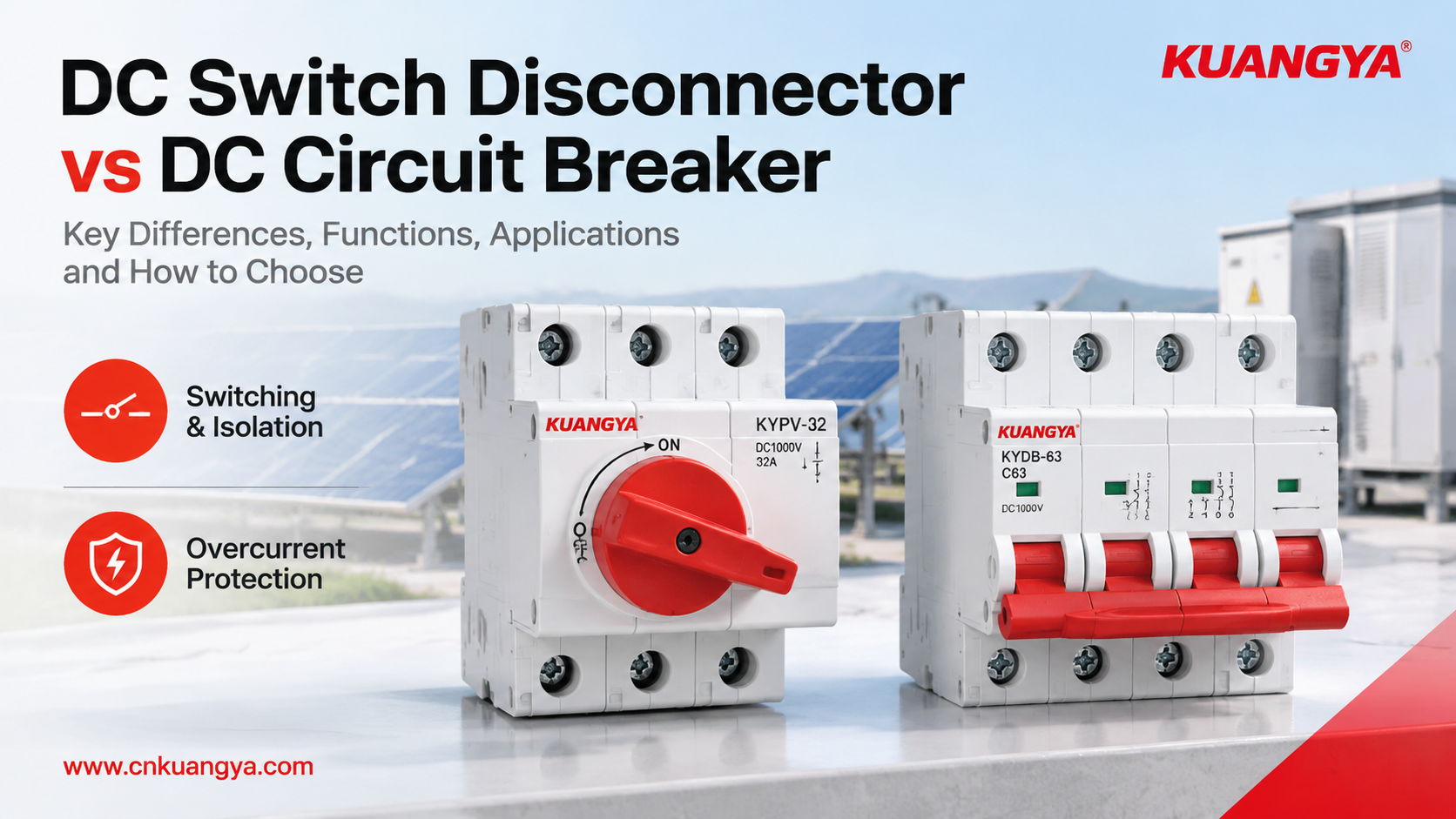
In a solar PV system, a DC switch disconnector vs DC circuit breaker comparison helps engineers and buyers understand two different functions: switching and isolation versus automatic overcurrent protection. Although these devices may look similar, choosing the wrong one can leave a circuit without the protection it needs or make maintenance more difficult.
The difference between a DC switch disconnector vs. DC circuit breaker comes down to their intended functions: a switch disconnector provides switching and isolation within its rated operating conditions, while a circuit breaker is designed to interrupt specified overcurrents and short circuits automatically.
However, the distinction is not always as simple as the product name suggests. Some devices combine switching and isolation functions, and their actual capabilities depend on their ratings, design, and applicable standards.
This guide compares the two devices, explains six practical differences, and shows how to evaluate them in photovoltaic (PV) systems, combiner boxes, and other DC applications.
The key takeaway: A switch disconnector is not automatically a short-circuit protection device, and a circuit breaker should not automatically be assumed to provide every isolation function required for maintenance.
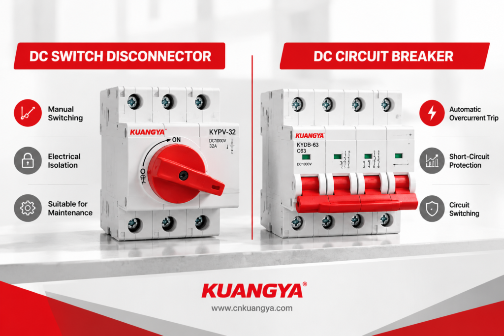
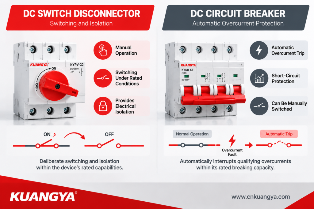
A DC switch disconnector is generally operated manually to connect or disconnect a circuit under specified conditions. A DC circuit breaker can automatically open a circuit when its protective mechanism detects an overcurrent within its operating characteristics.
| Comparison Point | DC Switch Disconnector | DC Circuit Breaker |
|---|---|---|
| Primary function | Switching and electrical isolation, according to its rating | Overcurrent protection and circuit switching |
| Normal load switching | Yes, if rated for the intended duty | Yes, within its rated operating conditions |
| Automatic overload trip | Not normally provided | Available on models designed for overload protection |
| Short-circuit interruption | Not its normal standalone function | Yes, within its rated breaking capacity |
| Isolation function | Depends on the device’s declared isolation capability | Depends on its design, markings, and applicable requirements |
| Typical operation | Manual handle or rotary mechanism | Manual operation and automatic tripping |
| Lockout provisions | May support a padlock in the OFF position | Depends on the model and accessories |
| Relevant IEC standard family | IEC 60947-3 | IEC 60947-2 for industrial circuit breakers |
| Typical PV application | Planned disconnection and maintenance isolation | Protection of suitable branches or feeders |
The comparison describes typical product functions rather than every device on the market. Always check the exact model’s datasheet and certification.
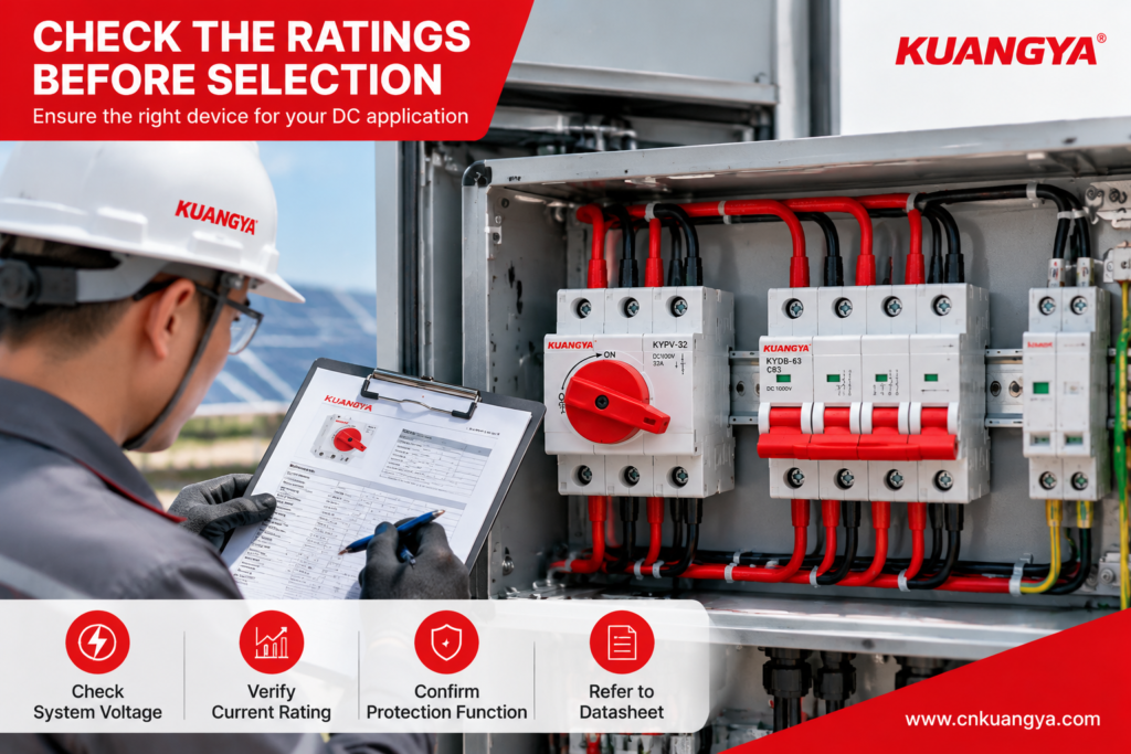
When evaluating a DC switch disconnector vs DC circuit breaker, do not compare products by rated voltage or current alone. Check whether the device is designed for load switching, electrical isolation, automatic tripping, or short-circuit interruption. These functions must match the actual requirements of the DC circuit.
Important: A basic disconnector intended only for isolation must not be treated as a load-breaking switch. Likewise, a switch disconnector must not be expected to interrupt a short circuit unless its specific rating or approved protective assembly permits that duty.
The most important distinction is what each device is designed to do.
A DC switch disconnector provides a deliberate means of opening a circuit. For product options and application details, explore our DC switch disconnectors for solar PV, energy storage, and other DC applications. It can help establish a defined isolation point before inspection, maintenance, or equipment replacement, provided the device is suitable for the application.
A DC circuit breaker protects an appropriately designed circuit against specified overcurrent conditions. Depending on its trip characteristics, it can respond to overloads and short circuits and interrupt the current within its rated capability.
Consider the following example:
A solar combiner box supplies a DC circuit connected to an inverter. During maintenance, a technician needs to isolate the relevant circuit. If an abnormal current occurs, the circuit also needs suitable protective equipment to interrupt the fault.
These are related but different requirements. The design should specify the appropriate isolation device and overcurrent protection rather than expecting one component to perform functions for which it has not been rated.
Not every switch is suitable for opening a loaded DC circuit.
DC current does not have the natural periodic zero crossings found in AC current. When DC contacts separate, an electrical arc can continue to conduct current unless the device is designed to interrupt it under the specified conditions.
A switch disconnector rated for the relevant DC switching duty can open a circuit within its declared limits. A disconnector intended for off-load isolation may require the current to be interrupted by another suitable device first.
Before selecting a device, check:
Do not assume that a rotary handle, a high voltage printed on the label, or a visible ON/OFF marking proves that a device can interrupt every type of DC load.
This is where the distinction becomes particularly important.
A DC circuit breaker is designed to interrupt specified fault currents within its rated breaking capacity and operating conditions.
When evaluating a circuit breaker for a DC application, review its rated breaking capacity and compatibility with the system’s prospective fault current. See our DC MCB range for product options and rated specifications.
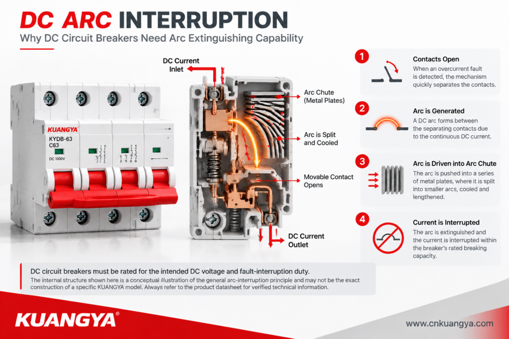
A switch disconnector, by contrast, is not normally intended to provide independent automatic short-circuit protection. It may have a specified short-time withstand capability or conditional short-circuit rating when used with a designated protective device.
These ratings mean different things.
| Rating or Feature | What It Tells You | What It Does Not Automatically Mean |
|---|---|---|
| Rated operational voltage | Voltage at which the device is intended to operate under specified conditions | That the device can interrupt any fault at that voltage |
| Rated current | Permitted current under the stated conditions | That overloads will trigger an automatic trip |
| Breaking capacity | Fault current a protective device can interrupt under specified conditions | That the device is suitable for every DC voltage or circuit arrangement |
| Short-time withstand current | Fault current the device can withstand for a specified duration | That it can independently clear the fault |
| Conditional short-circuit rating | Performance when used with the specified protective arrangement | That any fuse or breaker can be substituted |
For a DC switch disconnector, verify the declared short-circuit withstand or conditional rating and the required upstream protective device.
For a DC circuit breaker, check the rated DC breaking capacity and confirm that it is sufficient for the prospective short-circuit current at the installation point.
A conventional switch disconnector is operated manually. It does not normally detect an overload and trip automatically.
A circuit breaker with suitable protective functions can open a circuit when its trip mechanism detects a qualifying fault.
This difference affects system operation.
| Situation | Switch Disconnector | DC Circuit Breaker |
|---|---|---|
| Planned maintenance | Provides a suitable manual isolation point | May provide switching and isolation if specifically suitable |
| Sustained overload | Does not normally trip automatically | Can trip if its protection characteristics detect the overload |
| Short circuit | Must not be relied upon as standalone fault protection | Can interrupt the fault within its rated capability |
| Remote monitoring | Requires suitable auxiliary contacts or additional equipment | May support auxiliary contacts or electronic monitoring, depending on model |
| Automatic fault response | Not normally provided | Available according to the protection design |
A device’s ability to be switched remotely is not the same as its ability to provide automatic fault protection. Remote actuation, status monitoring, and protective tripping should be evaluated separately.
A 2-pole device is not automatically equivalent to a 4-pole device, and a voltage rating printed on a product should not be interpreted without checking the specified wiring arrangement.
Some DC switching devices use multiple contacts in series to achieve their declared voltage or interruption capability. In such cases, the manufacturer’s wiring diagram must be followed.
For example, a device rated for a particular DC voltage with a specified series-pole connection may not retain that rating when wired differently.
When comparing a DC switch disconnector with a DC circuit breaker, verify:
Do not choose a device based on “2P,” “4P,” or “1500V DC” alone. The complete combination of voltage, current, pole arrangement, and switching duty must match the intended application.
Maintenance safety involves more than turning a handle to OFF.
A suitable isolation arrangement should help personnel identify the correct circuit, prevent unintended reconnection, and follow the applicable safe-working procedure.
A DC switch disconnector may provide a lockable OFF position, but this feature must be confirmed for the specific model. A circuit breaker may also support locking accessories, although its suitability as the required isolation device must be verified separately.
For a planned maintenance task, consider the following:
An OFF indication alone is not proof that an electrical circuit is safe to touch.
In many photovoltaic installations, the switch disconnector and circuit breaker serve complementary roles.
A typical protection arrangement may include:
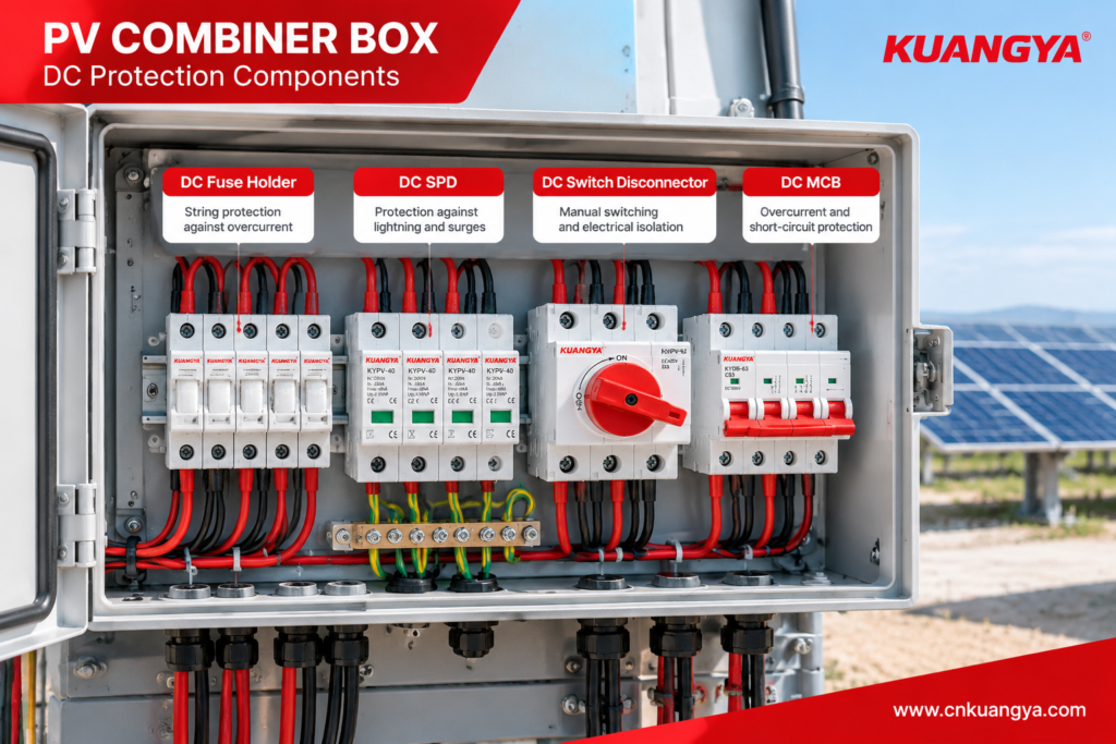
The exact arrangement depends on the system architecture, inverter requirements, prospective fault current, earthing arrangement, and applicable standards. For a closer look at how fuses, SPDs, disconnect switches, and other components work together, read our solar combiner box protection and maintenance guide. Not every installation requires all four devices in the same location.
| Component | Main Purpose | Selection Check |
|---|---|---|
| gPV fuse and fuse holder | PV string overcurrent protection | Rated voltage, current, fuse characteristic, and fault-interruption capability |
| DC SPD | Transient overvoltage protection | PV-specific rating, protection level, and applicable SPD standard |
| DC switch disconnector | Switching and isolation | Rated DC switching duty, isolation capability, and connection arrangement |
| DC circuit breaker | Overcurrent protection where required | Trip characteristics, rated breaking capacity, and system compatibility |
A combiner box with a fuse, SPD, and switch disconnector does not automatically provide every protective function that a circuit breaker would provide. Each component must be selected for its intended role.
For related technical guidance, see our Solar DC Protection Guide and PV Combiner Box Guide.
The following cases are illustrative engineering scenarios based on common equipment-selection and system-coordination issues. They are not presented as documented KUANGYA customer incidents or laboratory test results.
Situation
A panel designer selects a DC switch disconnector because its voltage and current ratings appear to match the circuit. The design does not include a suitable protective device for the relevant fault condition.
What is wrong?
The selected switch may be suitable for manual switching and isolation but may not have the capability to interrupt the prospective short-circuit current.
Corrective action
Lesson: A matching voltage and current label does not prove that a switch can clear a short circuit.
Situation
A buyer chooses an AC-rated switching device because its current rating appears sufficient for a solar DC circuit.
What is wrong?
The device may not have been tested or rated to interrupt the specified DC current. Its arc-extinguishing design and contact arrangement may be unsuitable for the application.
Corrective action
Use a device with an explicit DC rating for the actual system voltage, current, and switching duty. Follow the manufacturer’s approved wiring diagram.
Lesson: AC and DC ratings are not interchangeable unless the manufacturer explicitly declares the relevant capability.
Situation
A maintenance team assumes that switching a circuit breaker to OFF automatically satisfies all site isolation requirements.
What is wrong?
The breaker may not provide every required isolation, locking, or work-control feature for the particular installation. Other energy sources or backfeed paths may also remain present.
Corrective action
Check the device’s isolation suitability, locking provisions, circuit arrangement, and site procedures. Use the designated isolation method and verify the absence of voltage before work.
Lesson: Protection, isolation, and safe-work procedures are related but distinct requirements.
Use the following guide as a starting point, then confirm the choice against the applicable standard and the manufacturer’s documentation.
| Application Requirement | Appropriate Direction |
|---|---|
| Manual disconnection for planned maintenance | A suitable DC switch disconnector or isolator |
| Automatic overload protection | A suitably rated DC circuit breaker or other approved protective device |
| Short-circuit interruption | A protective device with sufficient DC breaking capacity |
| Both switching and isolation | A switch disconnector rated for the required duty, or another approved arrangement |
| PV string reverse-current protection | A correctly selected gPV fuse where required by the design |
| Transient overvoltage protection | A suitably rated DC SPD |
| Isolation and overcurrent protection | A coordinated combination of devices, unless an approved integrated solution provides the required functions |
For photovoltaic projects, the decision should be based on the system’s maximum DC voltage, current, prospective fault current, required isolation points, and applicable local requirements.
A device that is suitable for one part of a PV installation may not be suitable for another.
IEC 60947-3 covers switches, disconnectors, switch-disconnectors, and fuse-combination units within its scope. Buyers should check the applicable edition and the device’s declared ratings before selecting a product. IEC 60947-2 specifies requirements for circuit breakers within its scope, including relevant DC applications. Check the applicable edition and the manufacturer’s documentation to verify that the selected device meets the project’s requirements.
The applicable edition, product scope, and any relevant product-specific requirements should be checked for the intended application.
For more information about DC isolation principles and photovoltaic applications, see our DC switch disconnector technical guide.
Before issuing a purchase order, ask the supplier to confirm the following:
| Checkpoint | Information to Request |
|---|---|
| Product identity | Exact model and intended function |
| Voltage rating | Rated DC voltage and any limitations |
| Current rating | Rated operational or continuous current under stated conditions |
| Switching duty | Permitted load-breaking conditions and utilization category |
| Fault performance | Breaking capacity for breakers; applicable withstand or conditional rating for disconnectors |
| Pole arrangement | Approved wiring diagram and pole configuration |
| Isolation | Declared isolation suitability and operating indication |
| Locking | Whether the OFF position can be secured, if required |
| Standards | Applicable standard, edition, and supporting conformity documentation |
| Environmental suitability | Temperature limits, enclosure protection, terminals, and derating |
| Traceability | Model-specific datasheet, markings, and relevant test documentation |
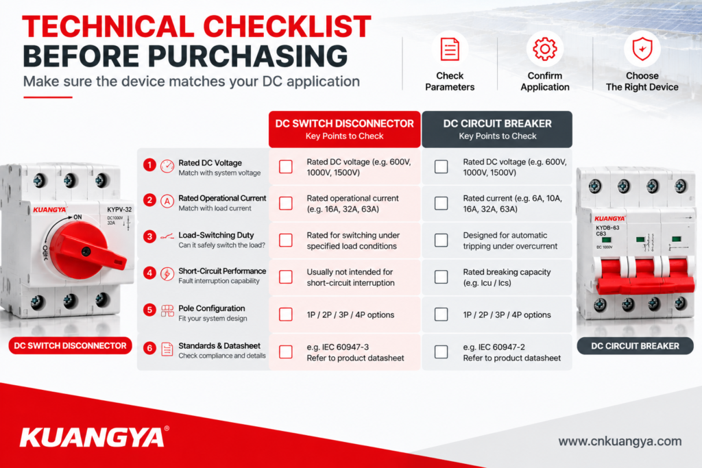
Avoid comparing suppliers solely by voltage, current, or unit price. Two products with similar front-panel markings may have different switching capabilities and short-circuit ratings.
No. A switch disconnector is intended for switching and isolation within its declared ratings. A DC circuit breaker provides automatic overcurrent protection within its rated protective capability. Their functions may overlap in some respects, but the devices are not automatically interchangeable.
Not as a general rule. A switch disconnector does not normally provide standalone automatic overload and short-circuit protection. A suitable protective device must be included where required by the system design.
Not automatically. Confirm that the breaker is suitable for the required isolation function, operating conditions, and maintenance procedures.
Each device must be rated for the actual maximum system voltage and its intended duty. A nominal 1500V system label alone is insufficient; verify the device ratings and approved connection arrangement.
IEC 60947-3 is relevant to switches, disconnectors, and switch-disconnectors. IEC 60947-2 is relevant to industrial circuit breakers. Other standards or requirements may apply depending on the product and installation.
Provide the application, maximum DC voltage, operating current, prospective fault current if known, required poles, switching duty, installation environment, quantity, and any required certifications or documentation. Include the system wiring diagram when possible.
Choosing the right DC switch disconnector vs DC circuit breaker solution starts with understanding the function each device needs to perform. A switch disconnector provides switching and isolation within its rated capabilities, while a circuit breaker provides automatic overcurrent protection within its rated breaking capacity. The final choice should match the system voltage, operating current, fault conditions, and applicable standards.
For solar PV systems, the right choice depends on the maximum DC voltage, operating current, prospective fault current, required isolation functions, and applicable standards. Always verify the manufacturer’s datasheet and ensure that all protective devices work together as intended.
KUANGYA provides DC switch disconnectors and DC protection components for photovoltaic and other electrical applications. If you are selecting components for a new project, contact our team with your system specifications to discuss a suitable solution.
Explore our DC Switch Disconnector and DC MCB product ranges for more information.