Промышленная зона Вэньян Юэцин Вэньчжоу 325000
Рабочие часы
Понедельник - пятница: 7AM - 7PM
Выходные: 10AM - 5PM
Промышленная зона Вэньян Юэцин Вэньчжоу 325000
Рабочие часы
Понедельник - пятница: 7AM - 7PM
Выходные: 10AM - 5PM
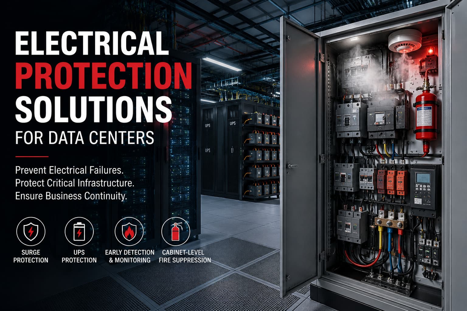
Data centers are designed around continuity. Redundant utility supplies, N+1 generators, dual UPS paths and multiple network connections are installed because even a brief interruption can affect thousands—or millions—of users.
Yet redundancy alone does not guarantee electrical safety.
The Uptime Institute’s 2025 survey found that power-related problems accounted for 45% of reported impactful data center outages. UPS failures were the most frequently identified cause among power-related incidents, followed by transfer-switch and generator failures. One in five respondents who experienced a significant outage estimated the total cost at more than USD 1 million.
These findings explain why Data Center Fire Protection cannot be treated as a separate system added after the electrical design is complete. It must be integrated into the complete power architecture, from the utility entrance and switchgear to UPS systems, battery cabinets, PDUs, busways, server racks and control panels.
A fire alarm may warn operators after combustion has already started. Effective electrical protection aims to detect abnormal conditions earlier, isolate the smallest affected circuit and suppress a developing fire before it spreads beyond the original enclosure.
TL;DR
- Power-related problems accounted for 45% of reported impactful data center outages in the Uptime Institute Global Data Center Survey 2025.
- Data center AC surge protection should be coordinated according to IEC 61643-11 and IEC 61643-12, while IEC 62305-4 addresses protection against lightning electromagnetic effects.
- UPS cabinets, server racks and electrical distribution panels require early detection, selective electrical isolation and appropriately engineered local fire suppression.
- A practical protection sequence is: incoming power assessment → coordinated SPD protection → UPS and battery protection → rack-level monitoring → cabinet-level fire suppression.
A data center power system contains many layers between the utility connection and the server processor:
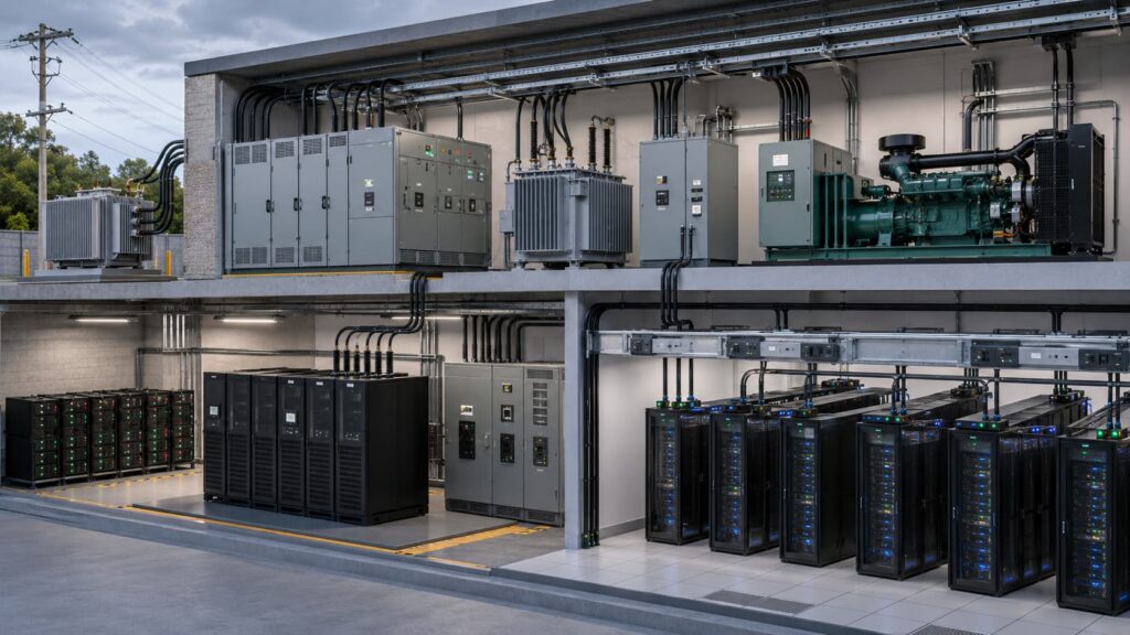
Every transfer point introduces conductors, terminals, switching devices and protective components. Each of these can become a source of heat, arcing or electrical instability.
A loose connection in a main switchboard may create localized resistance and overheating. A degraded UPS capacitor may fail internally. A battery module can develop an abnormal temperature condition. A damaged cable may produce an arc fault that remains below the instantaneous trip threshold of an upstream breaker.
The protection strategy must therefore consider both catastrophic faults and slow-developing conditions.
| Power-chain area | Typical risk | Potential result | Principal protection measures |
|---|---|---|---|
| Utility entrance | Lightning-induced surge, switching transient, voltage disturbance | Damage to switchgear, controls or downstream UPS equipment | Lightning protection, Type 1 SPD, grounding and bonding |
| Main switchboard | Loose connection, insulation breakdown, excessive fault current | Arc flash, busbar damage, fire and site-wide outage | Selective breakers, thermal monitoring, arc-flash assessment |
| Automatic transfer switch | Contact wear, mechanical failure, control fault | Failed transfer, overheating or simultaneous source conflict | Preventive maintenance, interlocking and temperature supervision |
| UPS input and output | Semiconductor failure, capacitor degradation, overload | Loss of conditioned power, smoke or internal fire | Internal protection, external isolation, monitoring and local suppression |
| Battery room or cabinet | Internal short circuit, thermal runaway, gas release | Prolonged fire, toxic products and loss of backup capacity | Battery management, ventilation, detection, separation and suppression |
| PDU or busway | Loose tap-off, overloaded conductor, poor coordination | Localized heating and downstream outage | Correct cable sizing, selective protection and thermal inspection |
| Server rack | Overloaded rack PDU, damaged cord, failed power supply | Rack-level smoke, equipment damage and service interruption | Rack monitoring, branch protection and server rack fire protection |
| Control cabinet | Relay, fan, power supply or terminal failure | Hidden enclosure fire and loss of control functions | Electrical cabinet fire suppression and early detection |
The objective is not simply to install more protective devices. Poorly coordinated protection can cause a minor branch fault to shut down an entire electrical path.
A correctly engineered system isolates the smallest practical section while maintaining power to unaffected loads. This principle is particularly important in 2N and distributed-redundant architectures, where a protection device that trips too broadly can defeat the benefit of redundancy.
Availability protection and fire protection are closely related, but they are not identical.
Availability engineering focuses on keeping the IT load energized. Fire protection focuses on preventing ignition, limiting fire growth, protecting occupants and controlling damage. In some situations, these objectives can conflict.
For example, immediately de-energizing an entire UPS path may reduce fire risk but cause an avoidable service interruption. Keeping equipment energized for too long may preserve uptime temporarily while allowing an internal fault to grow.
A mature Data Center Fire Protection plan establishes clear operating priorities before an emergency occurs.
| Protection objective | Main question | Typical response |
|---|---|---|
| Personnel safety | Could the fault expose staff to electric shock, arc flash or hazardous smoke? | Restrict access and isolate the hazardous circuit |
| Fire containment | Can the fault spread beyond the original cabinet or room? | Activate local suppression and maintain compartmentation |
| Защита оборудования | Can high-value equipment be saved without increasing risk? | Isolate the affected branch and maintain unaffected systems |
| Service continuity | Can workloads transfer to another electrical or IT path? | Initiate controlled failover before broader shutdown |
| Восстановление | Can the failed equipment be inspected without disturbing evidence or creating secondary damage? | Secure the area and follow a documented recovery procedure |
The protection sequence should be developed jointly by electrical engineers, fire protection engineers, facilities teams, IT operations and the local authority having jurisdiction.
NFPA 75, Standard for the Fire Protection of Information Technology Equipment, specifically addresses the protection of IT equipment and IT equipment areas against fire damage and associated effects. It should be considered together with applicable electrical, building, fire alarm, clean-agent, sprinkler, battery and local code requirements.
Most electrical failures do not begin as visible flames. They develop through heat, insulation deterioration, unstable voltage, abnormal current or mechanical degradation.
Identifying these conditions early is one of the most effective ways to improve Data Center Electrical Protection.
Bolted connections can loosen because of vibration, thermal cycling, incorrect installation torque or conductor movement. As contact resistance rises, the connection generates more heat under load.
Because the current may remain within the normal operating range, an upstream breaker may not trip. The first obvious indication may be discoloration, insulation odor, thermal-camera detection or smoke.
High-resistance connections are especially concerning at:
Routine infrared thermography is useful, but it only shows the condition at the time of inspection. Permanently installed temperature sensors provide better protection for continuously loaded or inaccessible connections.
Data center loads change frequently. Servers are replaced, rack densities rise and temporary equipment becomes permanent. A branch circuit that was correctly sized during commissioning may later operate near its thermal limit.
Three-phase imbalance can also increase neutral current and create uneven loading across distribution equipment.
Circuit breakers and fuses must be selected according to conductor capacity, available fault current, load characteristics, ambient temperature and coordination requirements. Oversizing protection to avoid nuisance trips is not an acceptable solution because it can allow conductors and terminals to operate above safe temperatures.
An arc can occur across damaged insulation, contaminated surfaces, loose connections or improperly separated conductors. Some series arc faults draw less current than a conventional short circuit and may not immediately operate an upstream overcurrent device.
The resulting plasma can produce extreme localized heat, molten metal and rapidly expanding gases. In higher-voltage distribution systems, the event also creates a severe hazard for maintenance personnel.
Arc-flash analysis, equipment labeling, remote operation, appropriate personal protective equipment and disciplined maintenance procedures remain essential. However, personnel protection measures do not eliminate the need to prevent the initiating fault.
A UPS is intended to protect the IT load from power interruption, but the UPS itself contains components subject to electrical and thermal stress.
Potential failure points include:
UPS systems should be selected and evaluated under applicable safety requirements. UPS systems used in critical data center facilities should be selected and evaluated under recognized electrical and fire safety requirements. Equipment supplied for North American projects is commonly assessed according to UL 1778 for Uninterruptible Power Systems, which covers safety requirements for UPS equipment, including electrical, mechanical, fire and abnormal operating hazards.
The Uptime Institute’s 2025 data reinforces the importance of UPS Cabinet Protection: UPS failures accounted for 42% of power-related IT service outages in the separate resiliency research cited by the survey.
Data centers may use valve-regulated lead-acid batteries, lithium-ion systems or other battery technologies. Each chemistry has different failure mechanisms and response requirements.
Lead-acid installations require consideration of short-circuit current, hydrogen generation, electrolyte leakage and connection heating. Lithium-ion systems add the possibility of cell-level thermal runaway, propagation and flammable gas release.
A battery management system is an important control layer, but it should not be treated as an absolute guarantee against failure. Detection, physical separation, ventilation, current interruption and an appropriate suppression strategy must be designed around the selected battery chemistry.
NFPA research notes that several standards—including NFPA 75, NFPA 76, NFPA 111 and NFPA 855—address aspects of fire risk associated with larger battery installations. The applicable requirements depend on the battery type, installation purpose, energy capacity and local code interpretation.
A data center can experience transient overvoltages from lightning, utility switching, transformer energization, generator transfer, capacitor switching and the operation of inductive loads.
These transients may not cause an immediate outage. Instead, repeated stress can weaken insulation and damage sensitive control boards, UPS electronics, monitoring systems, network equipment and server power supplies.
That makes surge protection both an availability measure and a fire-prevention measure.
| Failure mode | Early warning signs | Why normal protection may be insufficient | Recommended control |
|---|---|---|---|
| Ослабленное соединение | Rising terminal temperature, odor or discoloration | Current may remain below breaker trip level | Torque control, thermal monitoring and inspection |
| Деградация изоляции | Leakage current, partial discharge or intermittent alarms | Fault may develop gradually | Insulation testing and condition monitoring |
| Перегрузка | Sustained high current and elevated conductor temperature | Protection may be oversized or thermally affected | Load monitoring and correctly rated OCPDs |
| Series arc | Irregular current waveform, localized heat or noise | Arc current may be too low for instantaneous trip | Arc-fault assessment and early smoke detection |
| UPS internal failure | Fan alarm, capacitor warning, temperature increase | Internal fault may be downstream of external protection | UPS diagnostics, isolation and cabinet-level suppression |
| Battery fault | Cell-temperature deviation, swelling or gas alarm | Failure may propagate after circuit isolation | BMS, separation, ventilation, detection and suppression |
| Переходное перенапряжение | Repeated control failures or SPD status alarm | Event duration is too short for a breaker to respond | Coordinated SPD system |
| Rack power fault | Hot plug, damaged cord or repeated PDU alarm | Upstream protection may cover many racks | Branch-level protection and rack monitoring |
Data center fires are relatively uncommon, but their consequences can be disproportionate.
Uptime Institute reported that its member database contained only 11 data center fires among more than 8,000 abnormal incidents recorded from 1994 to 2021. Most were contained successfully. However, the same organization later identified 14 publicly reported, high-profile outages caused by fires or fire-suppression systems between 2020 and early 2023.
The correct conclusion is not that fire protection is unnecessary. It is that containment normally works—but the small number of failures that escape containment can become catastrophic.
On March 10, 2021, a fire occurred at the OVHcloud Strasbourg data center site, affecting the SBG2 facility and forcing the wider site to suspend operations.
According to OVHcloud’s official incident update, SBG2 was largely destroyed and four of the twelve rooms in the adjacent SBG1 facility were also destroyed. SBG3 and SBG4 were not physically damaged, but their servers were shut down during the emergency. No injuries were reported.
The event demonstrated that physical proximity and shared site dependencies can expand the operational impact beyond the building in which the fire begins.
It also highlighted several essential questions for Data Center Fire Protection:
A redundant server located in the same fire zone is not true disaster recovery. Similarly, two electrical paths passing through the same vulnerable room may be electrically redundant but not physically independent.
In October 2022, a fire occurred at an SK C&C data center in Pangyo, South Korea. Uptime Institute reported that the fire began in a battery room and took approximately eight hours to control.
The incident took tens of thousands of servers offline and disrupted services associated with KakaoTalk, mobile payments, transportation, gaming, music and other digital platforms used by millions of people. Naver services were also affected.
The precise technical cause was disputed publicly, but the operational lesson is clear: a fire in supporting electrical infrastructure can disable far more than the equipment inside the original room.
| Incident | Initial area | Wider impact | Principal design lesson |
|---|---|---|---|
| OVHcloud Strasbourg, 2021 | Data center building | Destruction of SBG2, partial damage to SBG1 and shutdown of unaffected site facilities | Separate buildings, power paths and recovery systems physically |
| SK C&C Pangyo, 2022 | Battery room | Large-scale interruption of messaging, payment, transport and online services | Treat battery rooms as critical fire zones with independent detection and containment |
| Accidental suppression events | Data halls or electrical rooms | Equipment damage or service interruption without a major fire | Protect against false activation and excessive discharge pressure |
These cases show why suppression-system selection requires the same engineering discipline as electrical protection.
Uptime Institute has noted that accidental discharge from high-pressure clean-agent systems has caused serious disruption in some financial and trading data centers. Its 2025 survey also recorded fire-suppression systems as the reported cause of 6% of respondents’ most recent impactful incidents.
A suppression system that creates unacceptable pressure, triggers unnecessarily or damages storage hardware does not provide resilient protection.
No single protective device can cover the complete data center power chain.
A well-designed system uses several layers, each addressing a different fault type and operating timescale.
| Уровень защиты | Main function | Typical equipment |
|---|---|---|
| Grounding and bonding | Establish a controlled fault-current and surge path | Grounding conductors, bonding bars and equipotential connections |
| Lightning protection | Intercept and conduct direct lightning current | Air terminals, down conductors and earth termination |
| Защита от перенапряжения | Limit transient overvoltage | Type 1, Type 2 and Type 3 SPDs |
| Защита от перегрузки по току | Interrupt overloads and short circuits | Fuses, circuit breakers and electronic trip units |
| Arc-energy reduction | Reduce arc duration or incident energy | Zone-selective interlocking, maintenance switches and arc relays |
| Тепловой мониторинг | Identify abnormal heat before ignition | Fixed sensors and infrared inspection |
| Smoke and gas detection | Identify combustion or battery off-gassing | Aspirating detection, point detectors and gas sensors |
| Local suppression | Control fire inside the initiating enclosure | Cabinet aerosol, clean agent or other listed systems |
| Room suppression | Control fire at room level | Sprinkler, water mist, clean agent or hybrid systems |
| Compartmentation | Restrict smoke, heat and flame spread | Fire-rated walls, doors and cable-sealing systems |
| Operational resilience | Maintain or restore service | Redundant power paths, workload failover and recovery procedures |
These layers should be independent enough that one failure does not remove every form of protection.
For instance, a building management system should not be the only means of identifying an overheated UPS terminal if that same terminal failure can interrupt power to the monitoring network. Critical alarms require resilient power, communication and escalation paths.
The same principle applies to fire suppression. Room-level protection may be necessary, but localized Electrical Cabinet Fire Suppression can control an enclosure fire before room conditions reach the main-system activation threshold.
An SPD for Data Centers protects equipment against short-duration overvoltage events that conventional circuit breakers and fuses cannot interrupt quickly enough.
IEC 61643-11:2025 defines performance and safety requirements for SPDs connected to AC low-voltage power systems. The standard describes SPDs as devices intended to limit surge voltage and divert surge current caused by lightning effects or other transient overvoltages.
Installing one SPD at the main switchboard is rarely enough for a large data center. For facilities requiring coordinated protection at service entrances, ATS panels, UPS inputs and downstream distribution boards, KUANGYA’s AC surge protective device range includes Type 1, Type 1+2, Type 2 and Type 2+3 configurations for commercial and industrial power systems.Cable length, distribution impedance and internally generated switching transients can expose downstream systems even when the service entrance is protected.
A coordinated approach is more effective.
| Installation location | Typical SPD class | Protection objective |
|---|---|---|
| Service entrance or lightning protection boundary | Type 1 or combined Type 1+2 | Discharge high-energy lightning and utility-originated surges |
| Main low-voltage switchboard | Тип 2 | Limit residual voltage entering the internal distribution system |
| Generator and ATS distribution | Тип 2 | Control switching and transfer-related transients |
| UPS input | Тип 2 | Protect rectifier and control electronics |
| UPS output or critical distribution board | Selected Type 2 or Type 3 | Protect downstream PDUs and sensitive equipment |
| Remote power panel | Type 2 or Type 3 | Reduce voltage stress close to the load |
| Sensitive control or monitoring equipment | Тип 3 | Provide fine protection at equipment level |
| Network and signal circuits | Signal-line SPD | Protect communication, control and monitoring ports |
Engineers who need a clearer comparison of protection classes, installation positions and backup-power applications can review this guide to surge protective devices for electrical systems.
Several parameters must be checked before selecting an SPD:
The SPD’s maximum continuous operating voltage must suit the actual system voltage and grounding arrangement. Selecting a value that is too low can cause premature degradation or failure during temporary overvoltage conditions.
Selecting a value that is unnecessarily high may result in a higher voltage protection level and weaker protection for sensitive electronics.
The required discharge capability depends on exposure, lightning protection design, installation position and coordination with upstream devices.
A service-entrance SPD is exposed to different energy than an SPD installed beside a UPS control cabinet. Applying the same device at every level is rarely the best engineering decision.
The voltage protection level must be low enough to protect the connected equipment after cable-related voltage drop and coordination effects are considered.
A high-current SPD with a poor residual-voltage characteristic may survive the surge while still allowing damaging voltage to reach the load.
The selected SPD and its backup protection must be suitable for the available short-circuit current at the installation point.
Data centers often have high fault levels because of large transformers, parallel sources and generator configurations. An SPD without adequate short-circuit withstand or correctly selected backup protection can become a hazard during failure.
Remote status contacts allow SPD alarms to be connected to the building management or data center infrastructure management platform.
Monitoring is essential because an SPD may reach end of life after repeated surge exposure without causing an immediate outage. A failed or disconnected SPD can leave the distribution path unprotected while appearing normal during routine operation.
The conductors between the SPD and the protected circuit should be kept as short and direct as practical. Excessive lead length adds inductive voltage during a surge and reduces the effective protection at the equipment terminals.
This detail is often more important than selecting a device with a slightly higher nominal discharge rating.
The UPS is one of the most critical and concentrated electrical systems in a data center.
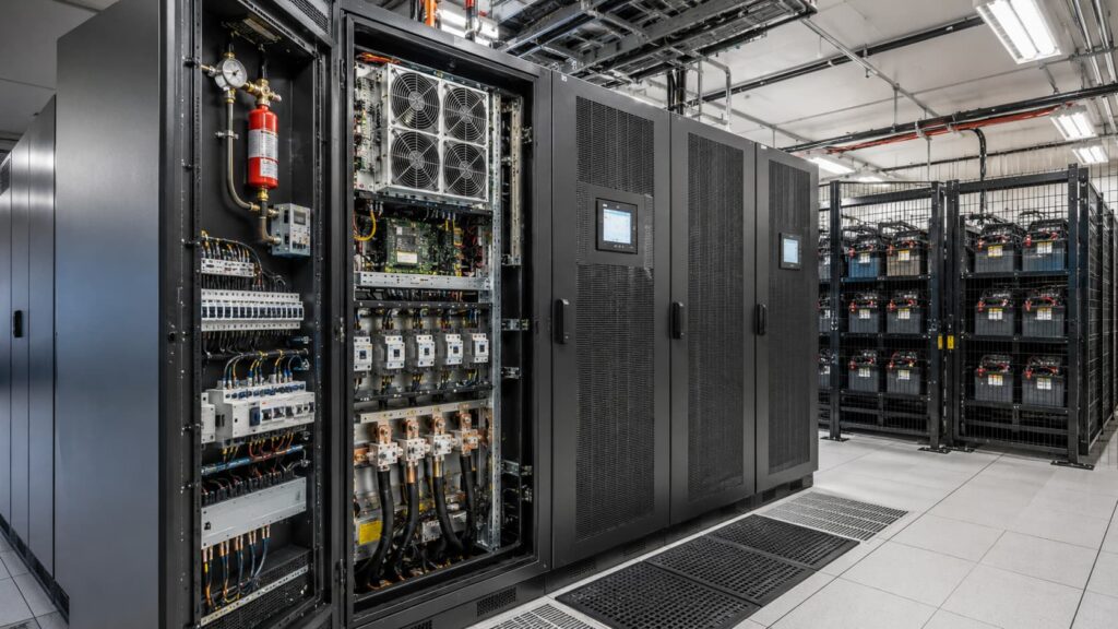
It connects utility power, generators, batteries, bypass circuits and critical IT loads. A serious UPS failure can therefore affect multiple parts of the facility at once.
Эффективный UPS Cabinet Protection should include:
The design must also consider maintenance bypass arrangements. A bypass circuit that has never been tested under realistic operating conditions may not provide the expected protection during an emergency.
The Uptime Institute’s 2025 survey found that 87% of respondents who had experienced an impactful outage during the previous three years believed the incident could have been prevented through better management, processes or configuration.
That finding is particularly relevant to UPS systems. Many UPS incidents involve more than a single component failure. Alarm handling, maintenance procedures, bypass configuration, protection settings and operator decisions can determine whether a manageable equipment fault becomes a site-wide outage.
Once incoming power, switchgear and UPS risks have been controlled, the protection boundary moves closer to the IT load. Power distribution units, busway tap-offs, rack PDUs, cable bundles and server power supplies require a more localized approach, where Server Rack Fire Protection, early detection and enclosure-level suppression become decisive.
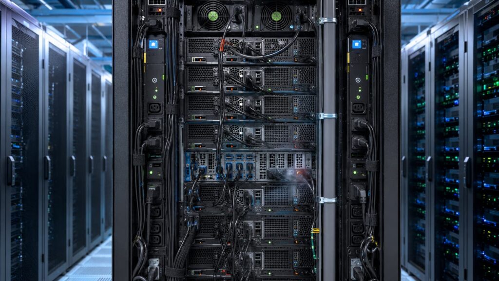
Once electrical power reaches the data hall, the protection challenge changes.
Upstream switchgear and UPS systems carry high fault energy, but an electrical fault inside a server rack may begin with only a damaged power cord, an overloaded rack PDU, a failed server power supply or a loose plug connection. The initial current may not be high enough to trip the upstream protective device immediately.
Modern racks also contain dense cable bundles, plastic connectors, printed circuit boards, fans and multiple power conversion components. A small electrical failure can therefore produce smoke and heat inside a narrow enclosure before conventional room-level detectors respond.
Эффективный Server Rack Fire Protection should address four stages:
| Rack-level risk | Typical cause | Early warning method | Recommended protective response |
|---|---|---|---|
| Overheated rack PDU | Continuous overload, loose receptacle or poor connection | Outlet-level current and temperature monitoring | Transfer workload, isolate the branch and inspect the PDU |
| Failed server power supply | Component aging, capacitor failure or fan obstruction | Server diagnostics, odor or localized smoke detection | Shut down the affected server and isolate its power feed |
| Damaged power cord | Excessive bending, crushing or poor connector engagement | Visual inspection and thermal monitoring | Replace the cable and inspect the upstream outlet |
| Cable-bundle heating | Excessive density, poor airflow or overloaded conductor | Temperature sensors and airflow alarms | Reduce load, improve routing and separate power cables |
| Rack-level arcing | Loose connector, damaged insulation or contamination | Very early smoke detection and waveform monitoring | Isolate the rack branch and initiate local response |
| Cooling failure | Fan failure, blocked airflow or loss of cooling supply | Inlet-temperature and pressure monitoring | Reduce IT load and activate controlled shutdown |
| Liquid-cooling leak | Failed fitting, damaged hose or condensation | Leak detection cable and pressure monitoring | Isolate coolant and electrical power according to procedure |
Rack power systems should provide branch-level visibility rather than relying only on the total load reported by the upstream PDU.
Intelligent rack PDUs can monitor current, voltage, power, energy and environmental conditions. The most useful systems also provide outlet-level data and configurable alarms. These functions help operators identify a deteriorating load before it becomes a fire risk.
Monitoring alone, however, does not remove the fault. Alarm thresholds must be linked to a documented response procedure. An alarm that remains unacknowledged for several hours provides little practical protection.
Data centers use large volumes of moving air to remove heat from IT equipment. Hot-aisle containment, cold-aisle containment and high-capacity cooling systems improve thermal efficiency, but they can also dilute and redirect smoke.
Research conducted through the NFPA Fire Protection Research Foundation has found that airflow containment and high-airflow environments create challenges for both smoke detection and extinguishing-agent distribution. Smoke may be pulled away from ceiling detectors, diluted below alarm thresholds or transported into another area before detection occurs.
For this reason, detector placement cannot be based only on room area.
The design should consider:
Aspirating smoke detection is often used in critical data center areas because it continuously draws air through a pipe network and analyzes the sample for very small smoke particles. UL notes that traditional detection can be less effective in high-airflow data centers and that aspirating systems can provide very early warning when sampling points are positioned close to server racks and airflow paths.
| Detection method | Main strength | Principal limitation | Suitable application |
|---|---|---|---|
| Ceiling point detector | Simple and widely understood | Smoke may be diluted or redirected by airflow | General room protection |
| Aspirating smoke detection | Very early warning and adjustable sensitivity | Requires engineered pipe layout and commissioning | Data halls, UPS rooms and high-value equipment areas |
| Rack-level smoke detector | Detects smoke near its source | More devices and maintenance points are required | High-density or high-risk racks |
| Linear heat detector | Detects temperature rise along a cable path | May respond later than smoke detection | Cable trays, busways and enclosed routes |
| Fixed temperature sensor | Provides continuous local condition data | Detects heat rather than smoke | PDUs, terminals, busway joints and cabinets |
| Battery off-gas detector | Can identify abnormal battery conditions before visible smoke | Must match the selected battery chemistry | Lithium-ion battery rooms or cabinets |
| Leak detection cable | Detects water or coolant release | Does not detect electrical overheating | Liquid-cooled racks and piping routes |
Detector sensitivity must be selected carefully. An excessively sensitive system may generate nuisance alarms from dust, maintenance work or environmental contamination. A system that is not sensitive enough may provide little advantage over conventional detection.
The correct approach is staged alarming.
A low-level alert can initiate investigation. A higher-level alarm can prepare electrical isolation and suppression systems. Confirmed detection from multiple inputs can then initiate the final emergency sequence.
Power distribution units, remote power panels and busways sit between the UPS output and the IT rack. They are often less visible than main switchboards, but their failure can interrupt an entire group of racks.
Common problems include:
These systems should be included in the same Data Center Electrical Protection program as the main switchgear.
| Protection measure | PDU | Remote power panel | Busway |
|---|---|---|---|
| Branch current monitoring | Требуется | Требуется | Recommended at each tap-off |
| Тепловой мониторинг | Рекомендуем | Рекомендуем | Important at joints and tap-off points |
| Selective breaker coordination | Требуется | Требуется | Требуется |
| SPD installation | Often appropriate | Site dependent | Site dependent |
| Remote alarm contact | Рекомендуем | Рекомендуем | Рекомендуем |
| Local fire detection | Risk based | Risk based | Useful in concealed routes |
| Cabinet-level suppression | Appropriate for selected enclosed units | Possible after engineering review | Usually limited to enclosed tap-off boxes |
| Periodic torque inspection | Required where permitted by manufacturer | Требуется | Required at accessible joints |
Busway systems require particular attention because one continuous run may supply many racks. A fault at one tap-off unit should not cause unnecessary loss of the entire busway section.
Protection settings must be coordinated with the available fault current, conductor ratings and downstream branch devices. Where electronic trip units are used, changes should be controlled through a formal management-of-change process.
An undocumented adjustment made to prevent nuisance tripping can increase both fire exposure and arc-flash energy.
Room-level suppression is important, but it does not always address the fire at its earliest point.In enclosed UPS, PDU and control panels, automatic fire suppression for electrical cabinets can provide an additional response layer close to the potential ignition source.
An electrical fault may remain contained inside an enclosed UPS cabinet, PDU, control panel, network power cabinet or battery auxiliary cabinet. The enclosure can delay the movement of smoke toward room detectors while heat continues to rise around the failed component.
Electrical Cabinet Fire Suppression places the extinguishing agent closer to the potential ignition source.
Potential applications include:
Cabinet-level protection is not intended to replace the building fire alarm, sprinkler system or room-level suppression system. It forms an additional layer designed to limit fire growth before the room system is required.
There is no single extinguishing technology suitable for every cabinet or data hall.A detailed comparison of aerosol and traditional fire suppression systems can help project teams evaluate installation space, maintenance requirements, discharge behavior and equipment recovery considerations.
Selection should consider the fire hazard, enclosure volume, ventilation, electrical status, personnel exposure, required cleanup, equipment sensitivity and local approval requirements.
| Suppression technology | Main advantage | Important design concern | Типичное применение |
|---|---|---|---|
| Clean agent | Low residue and suitable for many sensitive equipment areas | Enclosure integrity, agent concentration and discharge pressure | Data halls and enclosed electrical rooms |
| Inert gas | No chemical residue | High storage pressure and pressure-relief requirements | Large protected rooms |
| Water mist | Strong cooling effect with reduced water use | Equipment compatibility, nozzle design and water supply | Selected rooms and machinery areas |
| Sprinkler system | Established building-level fire control | Water exposure to IT equipment | General room and building protection |
| Condensed aerosol | Compact storage and no pressure cylinder in many designs | Residue, discharge temperature, clearances and equipment approval | Selected electrical cabinets and enclosed equipment |
| Direct-release tubing system | Detection and discharge close to the heat source | Tube routing, environmental limits and maintenance | Small electrical or equipment enclosures |
| CO₂ system | Effective extinguishing in enclosed machinery spaces | Serious personnel-safety restrictions | Normally limited to unoccupied specialized areas |
Before specifying an enclosure-level system, engineers should understand how to choose an aerosol fire extinguisher for electrical cabinets according to cabinet volume, operating temperature, activation method and equipment compatibility.
NFPA 2010 for Fixed Aerosol Fire-Extinguishing Systems provides requirements covering the design, installation, testing, inspection, operation and maintenance of fixed aerosol systems. Any aerosol-based Electrical Cabinet Fire Suppression installation should therefore be engineered and approved as a complete system rather than treated as a standalone device attached inside a cabinet.
For sensitive data center equipment, the evaluation should include:
A compact aerosol unit may be practical inside an electrical distribution cabinet where space is limited and a high-pressure cylinder is undesirable. For compact enclosed power and control panels, the 30g hot aerosol fire extinguishing device provides a thermally activated cabinet-level solution designed for protected volumes of up to 0.3 m³. It should not automatically be installed inside every server rack.
Server racks contain sensitive electronics, powerful fans and open airflow paths. The discharge behavior, residue, airflow interaction and recovery impact must be evaluated before selecting aerosol suppression for direct rack protection.
In many data halls, aerosol systems are better suited to enclosed power cabinets than to open IT racks.
The strongest Data Center Fire Protection design uses coordinated layers rather than relying on a single suppression system.
A developing cabinet fault may follow this sequence:
| Event stage | Detection or action | System response |
|---|---|---|
| Abnormal condition | Terminal temperature rises above warning level | Send alarm to DCIM or building management system |
| Early degradation | Repeated thermal or current alarm | Dispatch technician and prepare load transfer |
| Incipient smoke | Aspirating detector reaches first threshold | Investigate affected zone and verify equipment status |
| Confirmed cabinet event | Second detector or local thermal activation confirms fire | Isolate affected circuit and activate cabinet suppression |
| Room smoke development | Room detector confirms continued fire | Initiate room-level suppression sequence |
| Escalating event | Multiple alarms, heat or flame confirmed | Shut down affected zone and begin emergency response |
| Post-discharge condition | Fire appears controlled | Maintain isolation and inspect before re-energization |
The actual sequence must be determined through a site-specific cause-and-effect matrix.
Automatically shutting down cooling immediately after a smoke alarm may reduce smoke movement, but it can also accelerate overheating in unaffected servers. Keeping fans operating may preserve IT equipment temporarily while interfering with extinguishing-agent concentration.
These decisions require fire modeling, airflow analysis, electrical studies and consultation with the authority having jurisdiction.NFPA research on gaseous suppression systems in high-airflow environments further shows that airflow velocity, containment design and ventilation operation can influence agent transport and concentration.
Research commissioned through NFPA has specifically identified high airflow as a challenge for gaseous-agent distribution in IT and telecommunications environments.
A poorly designed or accidentally activated suppression system can itself damage equipment and interrupt service.
Uptime Institute has documented an incident in which an accidental inert-gas system discharge during testing damaged servers in a mission-critical facility. It has also warned that acoustic energy and pressure effects from high-pressure gas discharge can affect hard disk drives and other equipment.
Its 2025 survey reported an increase in the share of respondents identifying fire-suppression systems as the cause of their most recent impactful outage, potentially reflecting wider system deployment and accidental discharges.
Risk controls should therefore include:
A suppression control panel should also be powered from a reliable source and supervised for wiring faults, device removal, loss of communication and disabled zones.
An SPD for Data Centers should be coordinated with the electrical distribution system rather than installed as an isolated accessory.
IEC 61643-11:2025 applies to SPDs connected to AC low-voltage systems and covers devices intended to limit surge voltage and divert surge current caused by lightning effects and other transient overvoltages. IEC 61643-21:2025 separately addresses devices connected to telecommunications and signaling networks, including lines that may also deliver power through technologies such as Power over Ethernet.
This distinction matters because data centers contain both power and signal interfaces.
A complete strategy may require protection for:
Installing an SPD only on the main incoming power supply may leave control and communication paths exposed.
At the same time, SPDs must not interfere with normal signal operation. Signal-line devices should be selected for the operating voltage, data rate, transmission frequency, connector type and grounding arrangement of the protected circuit.
Every SPD has a maximum permissible backup fuse or breaker arrangement.
The upstream protective device must:
Remote status contacts should report SPD failure to the facility monitoring platform. A failed cartridge or disconnected SPD can otherwise remain unnoticed until the next surge event.
Electrical and suppression systems cannot compensate for poor physical separation.
Fire-rated walls, floors, doors and cable penetrations help stop smoke and flame from moving between data halls, UPS rooms, battery rooms, generator spaces and network areas.
NFPA 75 covers fire protection requirements for information technology equipment and areas containing that equipment. The current 2024 edition is intended to address protection against fire damage and associated effects in IT environments.
Cable penetrations deserve particular attention because data centers are constantly modified.
New network cables may be installed without restoring the original firestop system. Temporary openings may remain after old cables are removed. Bundles may exceed the tested configuration of the penetration seal.
A practical inspection should verify:
| Inspection point | Common deficiency |
|---|---|
| Wall penetration | Missing or damaged firestop material |
| Floor opening | Unsealed space around new cable bundle |
| Raised-floor boundary | Smoke path between fire zones |
| Door assembly | Door held open or damaged closer |
| Cable tray transition | Fire barrier interrupted by support system |
| Cooling-pipe penetration | Incorrect sealing material |
| Busway penetration | Gap around enclosure or missing fire-rated assembly |
| Decommissioned cable route | Empty opening left unsealed |
Physical separation should also apply to redundant systems.
Two UPS paths located in the same room, two network routes passing through the same cable shaft or primary and backup storage housed within the same fire compartment may create only logical redundancy—not genuine resilience.
Most data center electrical fires can be traced to a combination of equipment condition, installation quality and operational control.
A preventive-maintenance program should be based on risk rather than a fixed generic checklist.
| Частота | Recommended activity |
|---|---|
| Непрерывно | Monitor load, temperature, battery condition, SPD status and fire-alarm faults |
| Daily or weekly | Review critical alarms, disabled systems and unusual environmental trends |
| Ежемесячно | Inspect accessible cabinets, indicator lights, ventilation paths and housekeeping |
| Ежеквартально | Test alarm communication, supervisory circuits and selected interlocks |
| Раз в полгода | Inspect suppression devices, aspirating pipework and battery conditions |
| Ежегодно | Perform infrared thermography, protection review, suppression-system testing and firestop inspection |
| After modification | Recalculate loads, update drawings and verify protective-device coordination |
| After any discharge | Isolate, investigate, clean, replace activated devices and recommission the system |
Maintenance activities must be coordinated with operations.
Opening an energized cabinet, bypassing a UPS or disabling a suppression zone can temporarily increase risk. These actions should require an approved method statement, defined responsibility and clear restoration checks.
UL emphasizes that testing, certification and field evaluation can help demonstrate the safety and compliance of integrated data center power systems, including generators, inverters and UPS equipment.
Before approving a new data center or expansion project, the engineering team should confirm the following:
Надежный Data Center Fire Protection is not created by installing one detector or one extinguishing system.
It depends on the interaction between electrical design, overcurrent protection, surge protection, thermal monitoring, early smoke detection, battery safety, compartmentation, suppression and operating procedures.
The most effective strategy begins at the utility entrance and continues through switchgear, automatic transfer systems, UPS equipment, batteries, PDUs, busways and individual server racks.
A coordinated SPD for Data Centers limits transient overvoltage before it damages critical electronics. Selective fuses and circuit breakers isolate faulted circuits without unnecessarily shutting down healthy loads. Continuous monitoring identifies slow-developing heat and load problems. UPS Cabinet Protection и Electrical Cabinet Fire Suppression control faults close to their source, while room-level systems provide the final containment layer.
The goal is not merely to extinguish a fire.
The real objective is to prevent a minor electrical fault from becoming a prolonged outage, a multi-room event or a business-wide service failure.
Circuit breakers primarily respond to overloads and short circuits. Some dangerous conditions, including high-resistance connections, low-current arcing and component overheating, may not draw enough current to trip a breaker immediately.
Data Center Fire Protection therefore requires additional layers such as thermal monitoring, smoke detection, electrical isolation and suppression.
Usually not.
A service-entrance SPD can reduce high-energy external surges, but cable impedance, distribution distance and internally generated switching events can still expose downstream equipment.
A coordinated SPD for Data Centers strategy normally includes protection at the service entrance, main distribution boards, UPS boundaries and sensitive downstream equipment.
SPD placement depends on the UPS topology, grounding system, bypass arrangement and manufacturer instructions.
Common locations include the upstream distribution board, UPS input, bypass supply and critical downstream distribution. An engineer should confirm that the installation will not conflict with UPS operation, maintenance bypass functions or protective-device coordination.
UPS systems contain power semiconductors, capacitors, busbars, cooling fans, control electronics and connections to high-current batteries.
A failure can create heat, smoke or arcing while also threatening the power supply to critical IT equipment. This is why UPS Cabinet Protection should include electrical isolation, internal monitoring, battery supervision and an appropriate suppression strategy.
Не всегда.
Smoke may take time to leave a rack, especially when server fans and containment systems redirect airflow. Room-level suppression remains important, but high-risk racks may also need closer detection, branch-level isolation or localized protection.
The appropriate Server Rack Fire Protection method depends on rack density, airflow, equipment value and recovery requirements.
It can be considered for selected enclosed electrical cabinets when the system is correctly sized, approved and compatible with the protected equipment.
The design must evaluate enclosure volume, leakage, airflow, discharge temperature, residue, electrical clearances and maintenance requirements. Fixed aerosol systems should follow applicable requirements such as NFPA 2010 and local approval rules.
Condensed aerosol systems can produce particulate residue. The amount and impact depend on the agent formulation, discharge quantity, equipment layout, ventilation and cleanup procedure.
For this reason, an aerosol system should not be selected solely because it is compact. Compatibility with sensitive electronics must be evaluated before installation, particularly inside open server racks.
High airflow can dilute or redirect smoke before it reaches conventional ceiling detectors.
Aspirating systems continuously sample air through a pipe network and can identify very small smoke concentrations near racks, return-air paths or critical cabinets. Correct pipe layout and commissioning are essential because poor sampling-point placement can reduce performance.
Да.
High-pressure discharge can create pressure and acoustic effects, while accidental activation can cause unnecessary shutdowns and equipment damage. Data center systems therefore require pressure-relief design, confirmed detection, controlled testing and protection against accidental discharge.
The electrical system should use selective branch protection, intelligent rack PDUs, clear circuit labeling and coordinated breaker settings.
The operational plan should also support rack-level workload migration and controlled isolation. A branch fault should disconnect the smallest possible load without removing power from unaffected racks.
Critical loads and temperatures should be monitored continuously. Visual inspections, alarm reviews and housekeeping checks should occur regularly, while infrared thermography and detailed protection reviews are commonly performed at planned intervals.
The exact frequency should reflect loading, equipment age, environmental conditions, manufacturer requirements and previous inspection findings.
The most common strategic mistake is treating the fire alarm, electrical protection and IT resilience systems as separate projects.
A detector may identify smoke, but the facility still needs to determine which circuit should be isolated, whether cooling should remain operational, whether workloads can transfer and when suppression should activate.
A complete design connects detection, electrical isolation, airflow control, suppression and recovery through one tested cause-and-effect plan.
