WengYang Industrial Zone Yueqing Wenzhou 325000
Horas de trabalho
De segunda a sexta-feira: das 7h às 19h
Fim de semana: 10:00 - 17:00
WengYang Industrial Zone Yueqing Wenzhou 325000
Horas de trabalho
De segunda a sexta-feira: das 7h às 19h
Fim de semana: 10:00 - 17:00

Solar inverters operate at the electrical boundary between a continuously energized DC array and an AC distribution system. This position exposes them to lightning-induced surges, switching transients, reverse currents, insulation faults, overheating and sustained DC arcs.
Replacing a damaged inverter does not solve the underlying problem when the failure originated in the PV strings, combiner boxes, grounding system or AC network. Effective Proteção do inversor solar must therefore be designed as a coordinated system rather than as a single protective device.
This engineering guide explains how to combine surge protective devices, gPV fuses, disconnectors, grounding, arc-fault detection and thermal monitoring. It is intended for electrical engineers, EPC contractors, electricians, system integrators and operation and maintenance teams.
| Camada de proteção | Função principal | Typical equipment |
|---|---|---|
| Prevention | Reduce the probability of faults | Correct design, cable management, compatible connectors |
| Surge limitation | Divert transient energy | DC SPD, AC SPD, signal-line SPD |
| Overcurrent interruption | Stop excessive fault current | gPV fuse, circuit breaker |
| Fault detection | Identify abnormal electrical conditions | Insulation monitor, ground-fault detector, AFCI |
| Seccionamento | Disconnect the affected circuit | DC isolator, AC disconnect, remote shutdown |
| Thermal control | Prevent heat accumulation | Ventilation, derating, temperature monitoring |
| Containment | Limit fire propagation | Enclosure design, detection and suppression system |
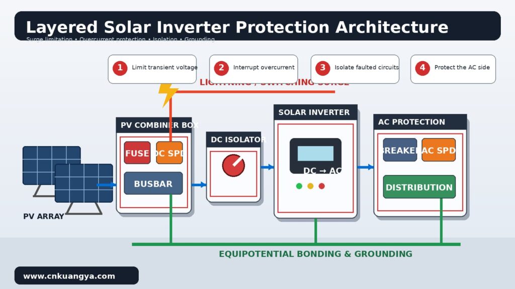
Solar Inverter Protection is the coordinated control of transient voltage, excessive current, insulation failure, electrical arcing and thermal hazards around a photovoltaic inverter.
The inverter is only one part of the protection zone. The zone normally includes PV strings, string cables, combiner boxes, DC isolators, DC inputs, AC outputs, grounding conductors and communication interfaces.
This means an inverter with internal protection functions can still be damaged by an external event. Internal electronic protection is not automatically a substitute for external SPDs, fuses, disconnectors or array-level fault detection.
IEC 62109-1 establishes general safety requirements for photovoltaic power conversion equipment against electrical shock, energy, fire, mechanical and related hazards. IEC 62109-2 adds requirements specifically applicable to PV inverters.
On the DC side, the inverter is connected to long outdoor conductors that can collect lightning-induced voltage. Multiple parallel strings may also feed reverse current into a faulted string.
On the AC side, the inverter is connected to a network that may experience utility switching, capacitor-bank switching, load rejection, transformer events or lightning-related disturbances.
Communication ports introduce a third path. RS485, Ethernet, monitoring and sensor cables can carry common-mode voltage into low-energy control electronics even when the main power terminals are protected.
Most severe failures develop through a sequence rather than a single event:
Bom Inverter Electrical Protection breaks this sequence before thermal damage becomes irreversible.
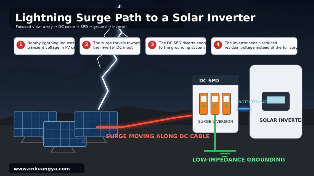
A direct lightning strike can inject a high-energy impulse into a structure, external lightning protection system, array frame, cable route or nearby ground.
A nearby strike can also induce transient voltage without directly hitting the PV installation. Long DC cable loops are particularly sensitive because electromagnetic coupling increases with loop area and conductor length.
A Solar Inverter SPD is designed to limit this transient voltage and divert surge current through a controlled path. It does not prevent lightning and does not absorb unlimited energy.
IEC 61643-31 covers SPDs intended for the DC side of PV installations up to 1,500 V DC. IEC 61643-32 provides principles for selecting, installing and coordinating SPDs on the DC and AC sides of PV systems.
The IEC 62305 series addresses lightning risk management, external lightning protection and surge protection measures. The 2024 editions cover the protection of structures, physical lightning damage and internal electrical or electronic systems.
Not every damaging surge is caused by lightning. Switching operations can also produce short-duration overvoltage.
Potential sources include transformer energization, inductive load switching, capacitor-bank operation, grid faults and disconnection of large electrical loads.
The resulting transient may enter through the inverter’s AC terminals. For this reason, installing only a DC SPD does not provide complete Proteção do inversor solar.
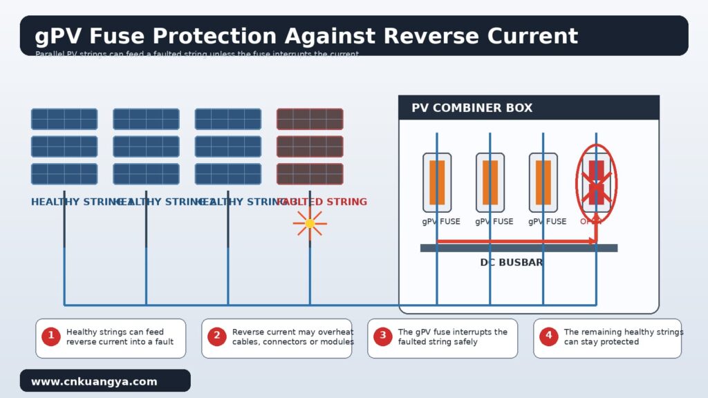
A PV module normally limits its own short-circuit current. However, when several strings are connected in parallel, healthy strings can feed reverse current into a faulted string.
This reverse current may exceed the safe current of the module cable, connector or junction box. A correctly selected gPV fuse can interrupt this current before the conductor or module is thermally damaged.
IEC 60269-6 contains supplementary requirements for fuse-links used to protect PV strings and arrays at nominal circuit voltages up to 1,500 V DC.
A fuse does not limit transient voltage. It also may not interrupt a high-resistance series arc because the arc current can remain close to normal operating current.For a more detailed comparison of their operating principles, see our engineering guide to DC Fuse vs DC SPD in Solar PV Systems.
A ground fault occurs when current flows from an energized conductor toward an exposed conductive part, grounded structure or protective conductor.
Moisture, damaged cable insulation, crushed conductors, connector contamination and incorrect cable routing can all reduce insulation resistance.
Continuous ground-fault current may create resistive heating and arcing. The IEA PVPS fire-safety report notes that ground faults can create both fire and electric-shock hazards.
Ground-fault detection must therefore be treated as a fire-prevention function, not merely as a personnel-protection function.
A series arc often develops at a loose connector, damaged crimp, broken conductor or poorly tightened terminal. Because the current still flows through the load, a normal overcurrent device may not operate.
A parallel arc occurs between conductors of different potential or between a live conductor and earth. It can produce higher current, but its magnitude still depends on array configuration and fault impedance.
DC arcs are dangerous because direct current does not cross zero every half-cycle.
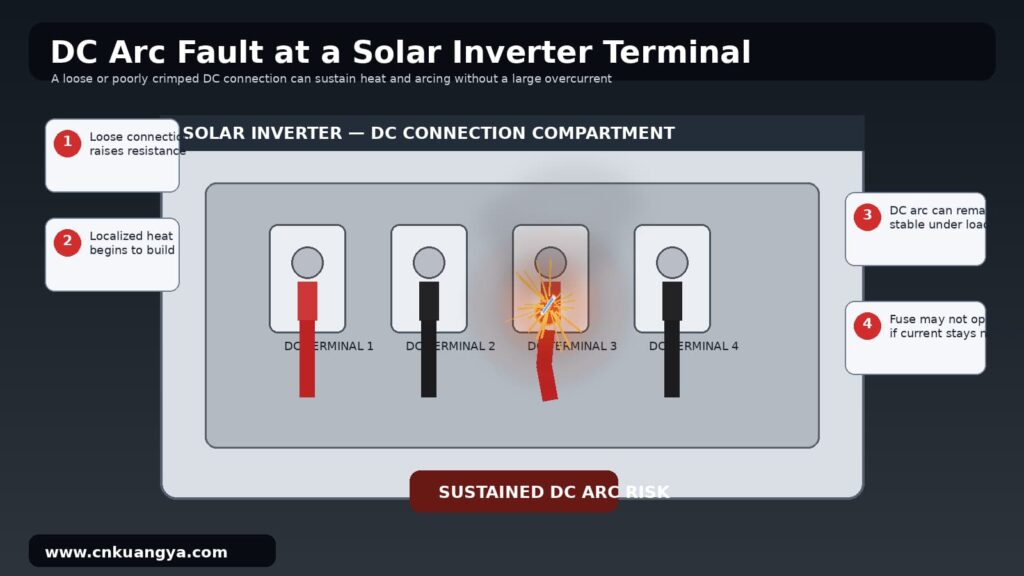
The arc can remain stable as long as the PV array continues supplying sufficient voltage and current.
IEC 63027:2023 applies to equipment used to detect and optionally interrupt DC arcs in photovoltaic circuits. It covers series-arc detection testing and the response of interruption equipment.
UL 1699B is used for photovoltaic DC arc-fault protection equipment in the North American market. Such equipment may be integrated into an inverter or installed as a separate protection device.
Power semiconductors, magnetics, busbars and terminals generate heat during normal operation. High ambient temperature, blocked ventilation, dust or inadequate clearance reduces the inverter’s thermal margin.
A loose terminal can create localized resistance heating without immediately causing a protective trip. This type of fault may remain invisible until discoloration, insulation damage or arcing occurs.
Fire protection therefore begins with electrical design, thermal management and maintenance. Similar failure mechanisms—including loose terminals, overheated fuse holders and degraded SPDs—also contribute to solar PV distribution box fire risks. An automatic suppression unit can limit fire development, but only after a failure has already escalated.
No single device can protect an inverter against every failure mechanism. This principle is part of a broader Solar PV protection strategy combining SPD, fuse and fire suppression, in which each device addresses a different stage of the electrical failure chain. Engineers should divide the system into protection zones and assign a specific function to each component.
The first step is to determine whether the site requires an external lightning protection system and how lightning current could enter the PV installation.
Os fatores importantes incluem:
IEC 62305-2 provides a procedure for assessing lightning risk and selecting measures that reduce risk https://webstore.iec.ch/en/publication/28137to an acceptable level.
A risk assessment is more reliable than selecting an SPD only from the inverter’s nominal voltage.
A correctly selected photovoltaic DC surge protective device protects the inverter input against transient overvoltage arriving from the PV array.
It must be specifically rated for photovoltaic DC applications. An AC SPD should not be installed on the DC array merely because its nominal voltage appears suitable.
A PV SPD must be capable of safely disconnecting at the end of its service life. DC systems can sustain follow current, so thermal disconnection and internal fault behavior are important.
For long DC cable runs, one SPD near the inverter may not be enough.A second coordinated SPD may be required inside the Caixa combinadora fotovoltaica near the array, particularly when the cable distance between the array and inverter is significant.
The AC-side SPD limits transients arriving from the utility network or facility distribution system.
Its voltage rating, protection mode and short-circuit withstand must match the actual earthing arrangement. TN, TT and IT systems may require different connection modes.
The AC SPD should be coordinated with upstream protection in the main distribution board. Poor coordination can leave the inverter exposed or cause one SPD to carry more energy than intended.
A Solar Inverter Fuse is required when the available reverse current from parallel strings can exceed the safe current of a module, cable or connector.
The need for string fusing depends on array topology, number of parallel strings, module maximum series fuse rating and conductor ampacity.
A gPV fuse is designed to interrupt DC faults across the operating range relevant to photovoltaic circuits. A general-purpose AC fuse should not be treated as an equivalent substitute.
For common 1,000 V DC string applications, a properly coordinated 10×38 gPV fuse link can provide overcurrent and short-circuit protection for PV strings, combiner boxes and inverter input circuits.
Disconnectors allow technicians and emergency personnel to isolate the inverter from external circuits.
The DC isolator must be rated for the full DC voltage, operating current, utilization category and circuit configuration. Pole arrangement matters because opening only part of a high-voltage DC circuit may leave hazardous potential present.
IEC 60947-3 applies to switches, disconnectors, switch-disconnectors and fuse-combination units up to 1,000 V AC or 1,500 V DC.
Isolation equipment must also remain accessible. A disconnect that cannot be safely reached during smoke, flooding or an electrical event has limited emergency value.
Grounding provides a controlled reference and a path for fault or surge current. Bonding reduces dangerous potential differences between conductive parts.
However, grounding is not simply the act of connecting everything to earth. Incorrect conductor routing can increase inductance and raise the residual voltage seen by the inverter.
The following practices improve Lightning Protection for Solar Systems:
At lightning frequencies, conductor length and geometry strongly affect impedance. A high-quality SPD connected through long, looped conductors may provide poor protection at the inverter terminals.
An insulation monitoring or ground-fault system should identify deterioration before it becomes a sustained thermal fault.
An AFCI should detect the electrical signature of a series arc and initiate interruption. The interruption method must remove the energy source rather than only generating an alarm.
Arc detection can produce nuisance trips when inverter switching noise, electromagnetic interference or unusual array conditions resemble an arc signature. Commissioning should therefore include verification under representative operating conditions.
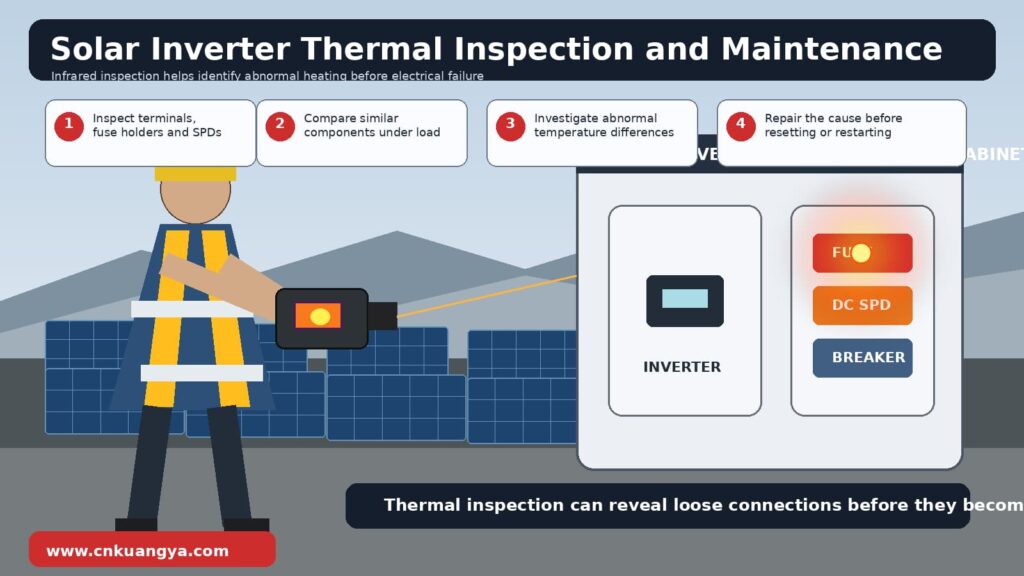
Thermal monitoring can reveal loose connections, overloaded components and ventilation problems before failure.
Useful methods include:
Alarm thresholds must be connected to an operating procedure. Recording a high-temperature alarm without assigning a response time does not reduce risk.
Power-side protection is incomplete when an unprotected communication cable enters the inverter.
RS485, Ethernet, weather sensors, external meters and remote I/O can introduce transient common-mode voltage into sensitive control boards.
Signal SPDs should be selected for the communication voltage, signal frequency, conductor arrangement and grounding system. Excessive capacitance or an incorrect SPD can degrade communication quality.
SPD selection should begin with the electrical system, not with a catalogue current rating.Engineers who need a parameter-based selection process can follow this guide on como dimensionar um DPS CC para um arranjo fotovoltaico solar.
The following parameters must be evaluated together.
| SPD parameter | Engineering purpose | Selection principle |
|---|---|---|
| Ucpv or maximum continuous operating voltage | Prevent unwanted SPD conduction | Must exceed the highest array voltage under the lowest design temperature |
| Up or voltage protection level | Limit residual voltage at equipment | Must remain below the inverter’s impulse withstand level with installation effects considered |
| Em | Nominal discharge-current capability | Used to compare repetitive Type 2 surge performance |
| Imax | Corrente máxima de descarga | Indicates the maximum Type 2 discharge test value |
| Iimp | Impulse current capability | Relevant to Type 1 protection and lightning-current waveforms |
| Modo de proteção | Defines protected conductor paths | Must match positive, negative and earth arrangement |
| Short-circuit capability | Ensures safe failure behavior | Must be compatible with available fault current |
| End-of-life indication | Supports maintenance | Local indication and remote contact are preferred for critical sites |
| Classificação de temperatura | Ensures environmental suitability | Must match enclosure temperature, not only outdoor ambient temperature |
The SPD voltage rating must be based on the maximum possible open-circuit voltage of the PV string.
Module open-circuit voltage increases as cell temperature falls. Engineers should calculate string voltage using the module temperature coefficient and the lowest expected cell or site temperature.
Using only the labels “1,000 V system” or “1,500 V system” can produce a dangerous selection error. The actual cold-condition voltage may approach or exceed the SPD’s continuous operating limit.
| Installation condition | Typical SPD approach |
|---|---|
| No external lightning protection system and mainly induced surge exposure | Type 2, subject to risk assessment |
| External lightning protection system with maintained separation distance | Coordinated Type 2 protection may be appropriate |
| Separation distance cannot be maintained | Type 1 or combined Type 1+2 generally required at the relevant boundary |
| Direct lightning current may enter incoming conductors | Type 1 protection required |
| Long cable distance between array and inverter | Coordinated SPDs at both ends may be required |
| High-consequence or critical installation | Multi-stage coordinated protection with monitoring |
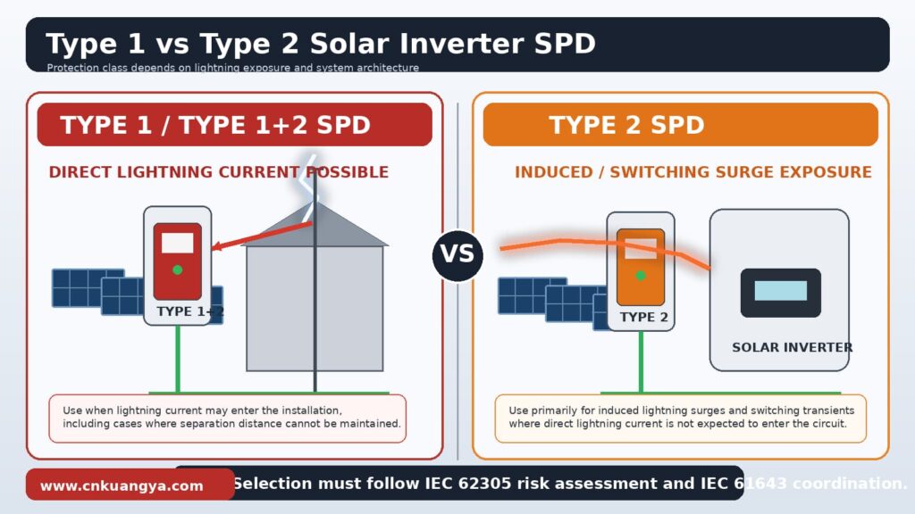
This table is a design guide, not a replacement for the project-specific requirements of IEC 62305, IEC 61643-32 and local electrical codes.
Buyers often compare SPDs only by Imax. This is incomplete because the inverter is affected by the residual voltage that remains after the SPD operates.
An SPD with a very high discharge-current rating may still provide unsuitable equipment protection if its Up value is too high.
The effective voltage at the inverter also includes voltage developed across the connection conductors. Shorter and straighter SPD connections reduce this additional voltage.
Pluggable SPD modules simplify maintenance because a failed cartridge can be replaced without rewiring the entire base.
Visual status indication allows basic inspection. A remote signalling contact is more useful for utility-scale plants, inaccessible rooftops and unmanned installations.
The remote alarm should be integrated into the plant monitoring platform. Otherwise, an exhausted SPD may remain unnoticed until the next inspection.
Fuse selection is not based only on normal string current. It must coordinate the module, conductor, connector and expected fault current.
| Fuse criterion | Required engineering check |
|---|---|
| Utilization category | Use a gPV fuse designed for photovoltaic protection |
| Rated DC voltage | Equal to or greater than maximum cold-condition circuit voltage |
| Corrente nominal | Above expected operating current after environmental correction |
| Module coordination | Must not exceed the module maximum series fuse rating |
| Cable coordination | Must protect conductor ampacity under actual installation conditions |
| Capacidade de ruptura | Must exceed the prospective DC fault current |
| Fuse-holder rating | Voltage, current and temperature ratings must match the fuse |
| Perda de energia | Must be acceptable inside the enclosure at full operating current |
| Certificação | Verify applicable IEC, UL or local-market compliance |
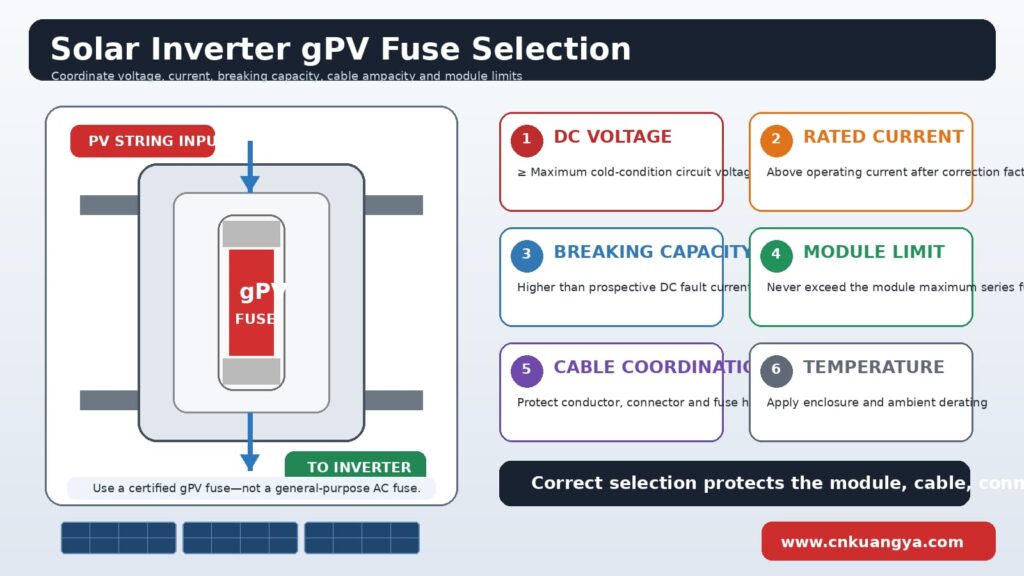
IEC 60269-6 applies specifically to fuse-links for PV strings and arrays. This distinction matters because PV circuits combine high DC voltage with fault currents that may be relatively close to normal operating current.
Oversizing a fuse reduces nuisance operation, but it may allow a damaged conductor or connector to overheat.
The final rating must remain below the weakest permitted current in the protected circuit. That limit may be set by the module, connector, cable, fuse holder or terminal.
A series arc can operate at nearly normal string current. Because no large overcurrent is present, the fuse may remain intact while the arc releases heat.
This means the Solar Inverter Fuse and AFCI perform different functions:
Complete Proteção do inversor solar normally requires several of these functions.
Protective components must operate as a system.
An SPD may require backup overcurrent protection. The backup device must follow the SPD manufacturer’s coordination instructions and must withstand the operating conditions of the PV circuit.
A fuse or breaker that operates too quickly may disconnect the SPD during a survivable surge. A device that operates too slowly may allow a failed SPD to overheat.
PV array → string fuse when required → combiner-box SPD → DC isolator → inverter DC input → inverter AC output protection → AC SPD → distribution board
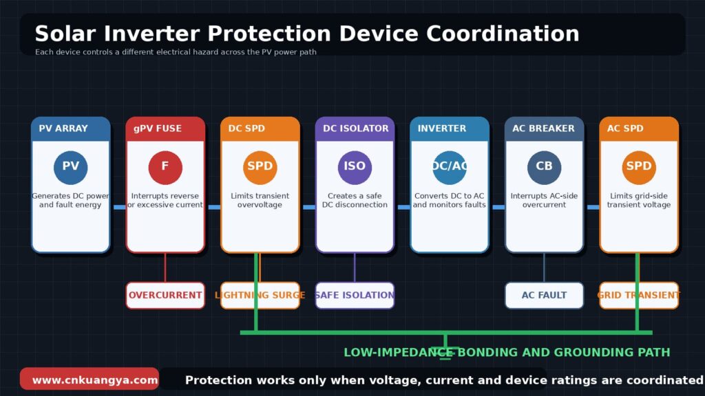
The exact sequence depends on enclosure design, national regulations and the inverter manufacturer’s requirements.
A common mistake is to select a breaker, fuse holder or SPD by voltage magnitude without confirming whether the device is suitable for DC interruption.
DC current does not naturally pass through zero. Contact spacing, arc chambers, pole configuration and magnetic polarity may therefore affect interruption performance.
Only components with clearly stated DC ratings should be used on the PV side.
The inverter manufacturer should provide maximum DC voltage, insulation category, impulse withstand information and permitted external protection.
The selected SPD must reduce the surge below a tolerable level at the actual inverter terminals. Cable inductance and installation distance must be included in this assessment.
The selected fuse or breaker must interrupt the available fault current without exceeding the inverter’s terminal, conductor or enclosure capability.
Even correctly rated components can fail when installation quality is poor.
Many field failures originate at interfaces: terminals, connectors, cable entries, fuse holders, isolators and grounding points.
Complete the following checks:
Crimping tools must match the specific contact system. A contact that appears mechanically secure may still have excessive resistance.
Mixing connector components from different manufacturers is especially risky when dimensional compatibility has not been verified. A connector may latch physically while producing insufficient contact pressure.
Cable entries should prevent water tracking into enclosures. Drip loops, gland orientation and cable support reduce mechanical stress at connectors and terminals.
The conductor between the protected line, SPD and grounding point should be as short and direct as practical.
Avoid coils, unnecessary bends and large loops. Route incoming unprotected conductors separately from outgoing protected conductors.
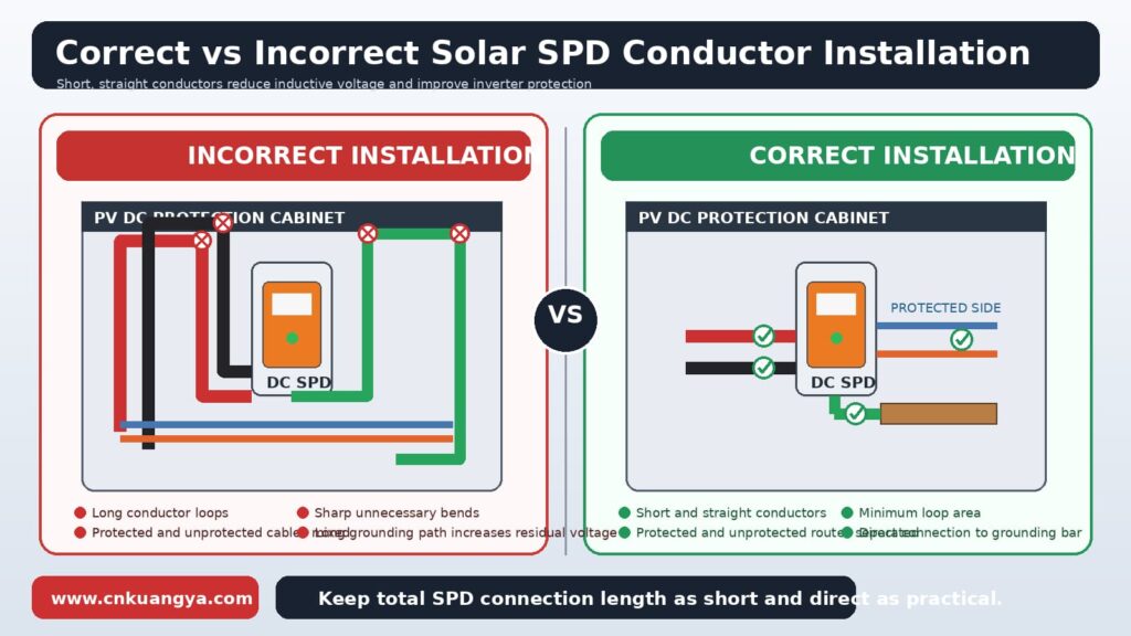
Where the distance between the SPD and inverter is excessive, evaluate whether an additional coordinated SPD is needed close to the equipment.
Measure terminal and enclosure temperatures after the system has operated near full output.
Infrared inspection can identify abnormal temperature differences between similar phases, poles, fuse holders or string circuits.
The important indicator is often the temperature difference between comparable components rather than one universal temperature threshold.
Protection devices are not “install and forget” components.
SPDs age after repeated surge exposure. Fuse holders can loosen through thermal cycling. Fans and filters accumulate dust. Cable insulation can be damaged by ultraviolet radiation, animals or mechanical movement.
| Inspection item | What to check | Typical response |
|---|---|---|
| estado do DPS | Indicator, alarm contact, physical damage | Replace failed module and investigate event |
| Fuse and holder | Discoloration, heat marks, contact pressure | Replace damaged components as a matched set |
| DC connectors | Cracks, loose locking, contamination | Isolate and replace correctly |
| Terminais | Torque, oxidation, temperature difference | Re-terminate under approved procedure |
| Aterramento | Continuity and corrosion | Restore bonding path |
| Insulation | Declining insulation resistance | Locate damaged circuit before restart |
| Inverter cooling | Fans, filters, airflow and alarms | Clean or replace components |
| Roteamento de cabos | Abrasion, sagging, water exposure | Repair support and insulation |
| Arc-fault logs | Repeated alarms or nuisance trips | Investigate connector and cable condition |
| Event logs | Surge, grid and insulation alarms | Correlate with weather and maintenance data |
Inspection frequency should be based on environment and consequence of failure. Coastal corrosion, desert dust, high humidity and severe lightning exposure justify shorter intervals.
Repeated insulation, arc or overvoltage alarms are evidence of an unresolved condition.
Resetting the inverter may restore production temporarily, but it can also allow a deteriorating fault to continue.
The affected string or circuit should be isolated and tested before returning it to operation.
Um IEA PVPS report on photovoltaic systems and firefighters’ operations summarized a German survey covering the period from 1995 to 2012.
The survey identified about 400 fire cases in which a PV system was present. In 180 cases, a PV component was determined to be the fire source.
Inverters and power electronics, connectors and terminals, and junction boxes were identified among the major ignition locations.
Engineering lesson: Inverter protection cannot stop at the inverter enclosure. Connection quality, combiner-box design and DC wiring must be included in the fire-risk assessment.
A 380 kW rooftop installation in Bakersfield, California, experienced two separate fires associated with a “blind spot” ground fault.
The report states that the absence of DC disconnect switches at the combiner boxes required an electrical worker to manually pull 56 fuses.
A later analysis indicated that an initial ground fault went undetected. A second ground fault changed the current path and contributed to an arc fire.
Engineering lesson: Ground-fault protection must detect credible multiple-fault conditions. Accessible isolation points are also essential for emergency response.
A Sandia and NREL analysis of PV connector failures reviewed hundreds of connector-related operation and maintenance records from utility-scale PV installations.
Within those 522 records, “ground fault” appeared 136 times, “burn” 90 times, “melt” 56 times, “arc fault” 40 times and “fire” 32 times. These categories were word occurrences and were not necessarily mutually exclusive.
The same analysis included field reports describing arcing connectors and small fires caused by short circuits at PV arrays.
For a modeled 100 MW utility-scale system, connectors represented approximately 6% of lifetime O&M cost and inverters approximately 5% in the component breakdown.
Engineering lesson: Small balance-of-system components can create inverter shutdown, lost production, fire exposure and substantial maintenance cost.
| Erro | Why it fails | Correct approach |
|---|---|---|
| Installing an SPD only on the AC side | Surges can enter through PV strings | Protect both DC and AC boundaries |
| Installing an SPD only on the DC side | Utility switching can affect AC terminals | Coordinate AC distribution protection |
| Selecting SPD voltage from nominal system voltage | Cold-condition Voc may be higher | Calculate maximum actual array voltage |
| Comparing only Imax | Imax does not define residual voltage | Check Up, Ucpv, type and coordination |
| Using an AC fuse in a PV circuit | DC interruption behavior may be inadequate | Use a certified gPV fuse |
| Oversizing string fuses | Cable or connector may overheat first | Coordinate with the weakest component |
| Assuming a fuse stops every arc | Series arcs may not create overcurrent | Use arc detection and interruption |
| Using long SPD conductors | Inductive voltage increases residual stress | Keep conductors short and direct |
| Mixing connector brands | Mechanical fit does not prove electrical compatibility | Use verified matching components |
| Ignoring communication ports | Surge can enter control electronics | Protect signal and data lines |
| Resetting repeated alarms | The fault remains active | Isolate, test and repair |
| Adding fire suppression but ignoring faults | Suppression acts after escalation | Prioritize electrical prevention and isolation |
A technical RFQ should contain enough information for the supplier to select and verify the component.
Provide:
Provide:
The supplier should also receive the single-line diagram, string configuration, cable distances, inverter model and local environmental conditions.
This allows the SPD, fuse, holder, isolator and enclosure to be evaluated as a coordinated system.
Kuangya supplies photovoltaic DC and AC surge protective devices, gPV fuse links, fuse holders and low-voltage protection components for solar and energy infrastructure projects.
For OEM, EPC and project applications, the most useful request includes the electrical diagram and technical parameters rather than only a product photograph.
Confiável Proteção do inversor solar requires more than installing one SPD beside the inverter.
Engineers must control the complete failure chain: lightning exposure, transient overvoltage, reverse current, ground faults, DC arcs, terminal heating and fire propagation.
A Solar Inverter SPD limits transient voltage. A Solar Inverter Fuse interrupts excessive current. Arc-fault and ground-fault systems detect conditions that may not produce sufficient overcurrent for a fuse to operate.
Grounding, cable geometry, connector compatibility, terminal torque and maintenance determine whether these protective devices can perform as designed.
The correct objective is not to make the inverter impossible to damage. The objective is to reduce fault probability, limit fault energy, isolate the affected circuit and prevent one component failure from escalating into a plant-level outage or fire.
For project-specific SPD and gPV fuse selection, provide Kuangya with the system voltage, string configuration, inverter model, cable distance and required standards. A coordinated protection proposal can then be prepared for the actual PV architecture.
Yes. The DC SPD protects against surges arriving from the PV array, while the AC SPD protects against transients arriving through the utility or facility distribution network.
Protecting only one side leaves another electrical path exposed.
Not automatically. Internal components may provide limited protection, but their surge rating, location and replacement method may not be sufficient for the site risk.
External protection should follow the inverter manufacturer’s instructions, IEC 61643-32, IEC 62305 and local regulations.
Type 2 is commonly used for induced surge protection where direct lightning current is not expected to enter the circuit.
Type 1 or combined Type 1+2 protection is generally required where lightning current may enter, such as when separation from an external lightning protection system cannot be maintained.
The final choice must be based on a project-specific lightning risk assessment.
Repeated failure can indicate an underrated Ucpv, excessive lightning exposure, incorrect grounding, long connection conductors, poor SPD coordination or temporary overvoltage.
Replacing the cartridge without investigating the cause may result in another failure.
No. A gPV fuse responds to overcurrent, while lightning protection requires an SPD capable of limiting transient overvoltage and diverting surge current.
A fuse and SPD perform different protection functions.
A series arc may carry approximately the same current as the normal operating string.
Because there is no significant overcurrent, the fuse may not operate. Arc-fault detection and circuit interruption are required for this type of fault.
Common causes include loose terminals, incorrect torque, undersized conductors, damaged contacts, contamination, poor crimping and repeated thermal cycling.
Infrared inspection and torque-controlled installation help detect or prevent these faults.
Fire suppression requirements depend on enclosure design, installation environment, equipment value and local regulations.
A suppression system may limit fire spread, but it must not interfere with ventilation, insulation or service access. Installation inside an inverter should not be performed without equipment-manufacturer approval.
Inspection frequency should reflect the site environment, lightning exposure, equipment criticality and manufacturer recommendations.
High-risk sites should include routine SPD status checks, thermal inspection, grounding verification, connector inspection and review of inverter event logs.

