주소
304 북쪽 추기경
세인트 도체스터 센터, MA 02124
근무 시간
월요일~금요일: 오전 7시~오후 7시
주말: 주말: 오전 10시 - 오후 5시
주소
304 북쪽 추기경
세인트 도체스터 센터, MA 02124
근무 시간
월요일~금요일: 오전 7시~오후 7시
주말: 주말: 오전 10시 - 오후 5시
When lightning strikes within a mile of your solar installation or EV charging station, the resulting surge can travel through your electrical system in microseconds, destroying inverters worth thousands of dollars, frying charge controllers, and rendering expensive battery banks useless. Yet most system owners discover they need surge protection only after catastrophic failure—when it’s already too late.
The question isn’t whether you need Surge Protection Devices (SPD), but which type belongs where in your system architecture. Installing a Type 2 SPD where a Type 1 is required, or placing devices at incorrect coordination points, creates dangerous protection gaps that leave your investment vulnerable. This comprehensive guide cuts through the confusion, providing actionable selection criteria and precise placement strategies for both solar photovoltaic systems and electric vehicle charging infrastructure.
The Type 1, Type 2, and Type 3 designations defined in IEC 61643-11 represent fundamentally different surge waveforms, energy handling capabilities, and installation locations—not simply a progression from “good” to “better.” Each type addresses specific threat scenarios in your electrical distribution system.
Type 1 surge protective devices stand as the first line of defense against direct lightning strikes and the massive energy they deliver. These devices must withstand the 10/350 μs impulse current waveform—a slow-rising, long-duration surge that carries enormous energy content. The “10/350” notation indicates a current that rises to peak value in 10 microseconds and decays to half that value in 350 microseconds, simulating the actual behavior of lightning current flowing through your grounding system.
Key Technical Specifications:
Type 1 SPDs employ spark-gap technology or heavy-duty metal oxide varistors (MOVs) capable of conducting massive fault currents to ground without self-destructing. For solar PV systems with rooftop arrays acting as lightning collectors, or EV charging stations with exposed outdoor equipment, Type 1 protection at the service entrance is non-negotiable.
Type 2 devices form the backbone of most surge protection strategies, defending against indirect lightning effects, switching transients from nearby equipment, and surges that penetrate past the service entrance. These SPDs handle the 8/20 μs waveform—a faster-rising, shorter-duration surge typical of induced voltages and grid disturbances.
Key Technical Specifications:
Type 2 SPDs are the most commonly deployed devices in residential and commercial installations. In solar applications, they protect inverter AC outputs and distribution panels. For EV charging, Type 2 units safeguard subpanels feeding wallbox circuits. Their lower voltage protection level (Up) compared to Type 1 devices provides tighter clamping for sensitive electronics while still handling substantial surge energy.
Type 3 surge protectors deliver the finest voltage clamping at the final connection point, protecting individual sensitive devices from residual surges that pass through upstream protection layers. These devices feature the lowest protection level (Up ≤ 1.5 kV) but have limited energy handling capacity.
Key Technical Specifications:
Critical limitation: Type 3 devices cannot function safely as standalone protection. They must always be installed downstream of a Type 2 SPD with proper coordination distance (typically 10+ meters of cable or a decoupling inductor). Installing Type 3 alone violates IEC 61643-11 requirements and creates a dangerous failure scenario where the device may be destroyed by surge energy exceeding its capacity.
Type 1+2 (also written T1/T2 or Type 1/2) devices combine both Class I and Class II test requirements in a single DIN-rail module. These hybrid units can handle both 10/350 μs lightning impulses and 8/20 μs induced surges, making them ideal for installations where space is limited or where a single protection point must serve dual functions.
Advantages:
Considerations:
For solar PV systems under 50 kW or EV charging stations with 1-4 charging points, Type 1+2 combined SPDs often represent the optimal balance of protection, cost, and simplicity.
Choosing the correct SPD type is only the first step. Three additional parameters determine whether your protection strategy succeeds or fails catastrophically.
The Uc rating defines the highest continuous voltage the SPD can withstand without degrading or entering a conduction state. This parameter must account for your system’s nominal voltage plus any temporary overvoltage (TOV) conditions that may occur during grid disturbances or ground faults.
Selection Rules:
For AC Systems:
For DC Solar PV Systems:
Common mistake: Selecting Uc based only on nominal voltage without accounting for open-circuit conditions, temperature effects, or grid TOV scenarios. An undersized Uc rating causes the SPD to conduct continuously, leading to thermal runaway and device failure—often accompanied by fire risk.
The Up value represents the maximum voltage that appears across the SPD terminals during a surge event. This let-through voltage directly impacts the stress experienced by downstream equipment. Lower Up values provide better protection but typically come with higher cost and may require more frequent replacement after surge events.
Coordination Strategy:
The Up values must be coordinated in a cascading system:
Each downstream device must have a lower Up than its upstream neighbor, creating a “staircase” of progressively tighter voltage clamping. This ensures surges are attenuated at each stage rather than bypassing protection layers.
Three current ratings define an SPD’s energy handling capability:
Iimp (Impulse current): Type 1 only. The 10/350 μs lightning current the device can conduct. Minimum 12.5 kA per IEC, but 25-50 kA recommended for exposed installations.
Imax (Maximum discharge current): The largest 8/20 μs surge the device can handle. Typically 40-65 kA for Type 2 devices in solar/EV applications.
In (Nominal discharge current): The 8/20 μs current used for classification and aging tests. The device must withstand this surge 15-20 times without degradation. Typical values: 5-20 kA for Type 2, 1.5-5 kA for Type 3.
Selection guideline: For critical installations (large solar arrays, fast-charging EV stations), specify Imax at least 2× higher than the calculated prospective surge current at that location.
Solar photovoltaic installations present unique surge protection challenges. Arrays mounted on rooftops or ground-mounted structures act as lightning collectors, while long DC cable runs between panels and inverters create inductive coupling paths for surge energy. Both the DC and AC sides require coordinated protection. 인용
Location 1: PV Array Combiner Box (if cable run > 10m)
When the distance between your solar array and inverter exceeds 10 meters, install a DC Type 2 SPD in the combiner box or junction box near the array. This first protection stage intercepts surges induced in the long DC cables before they propagate toward the inverter.
Specifications:
Wiring critical point: The SPD must be installed between any string fuses/breakers and the combiner output. If placed before the fuses, strings remain unprotected when fuses open. Keep connection leads to PE/ground under 0.5m total length (both L+ and L- leads combined). 인용
Location 2: Inverter DC Input (mandatory for all systems)
Every solar inverter requires DC surge protection at its input terminals, regardless of cable length. Modern inverters contain sensitive IGBT switching circuits, DSP controllers, and MPPT tracking electronics that are highly vulnerable to surge-induced failure.
Specifications:
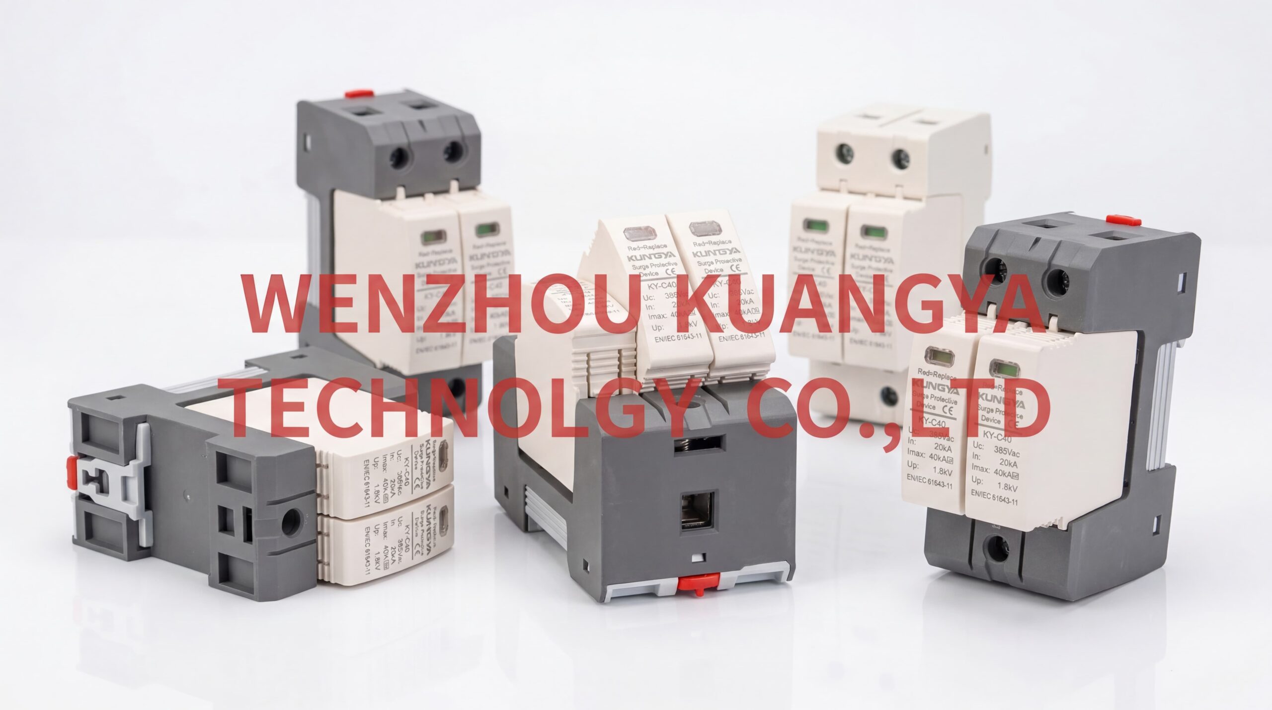
Product recommendation: Kuangya offers DC SPD modules specifically rated for 1000V and 1500V PV systems with Imax ratings from 20kA to 65kA, suitable for both residential and commercial installations. These units feature visual fault indicators and replaceable protection modules for easy maintenance. 인용
Location 3: Inverter AC Output
The AC side of your solar system connects to the building’s electrical distribution, creating a pathway for grid-side surges to enter the inverter. Install AC Type 2 SPDs at the inverter AC output or in the AC disconnect/distribution panel.
Specifications:
Location 4: Main Distribution Board
If your solar system connects to a building’s main distribution board (rather than a dedicated solar subpanel), install additional Type 2 AC SPDs at the main board to protect the entire facility.
Coordination distance: Maintain at least 10 meters of cable between the inverter AC SPD and main board SPD, or use SPDs with built-in decoupling inductors. This separation ensures proper energy sharing between protection stages.
System parameters:
Protection scheme:
| 위치 | 디바이스 유형 | Uc Rating | Imax | Product Example |
|---|---|---|---|---|
| Array combiner box | DC Type 2, 2P+PE | 1200V | 40 kA | Kuangya DC SPD 1000V series |
| Inverter DC input | DC Type 1+2, 2P+PE | 1200V | 65 kA | Kuangya DC SPD Type 1+2 combined |
| Inverter AC output | AC Type 2, 3P+N | 440V | 40 kA | Kuangya AC SPD Type 2 |
| 주요 배포 | AC Type 1, 3P+N | 440V | 50 kA | Kuangya AC SPD Type 1 |
Total protection investment: Approximately $800-1,200 to protect a $45,000+ system investment.
Electric vehicle charging infrastructure requires multi-stage surge protection, particularly for outdoor installations where charging pedestals are exposed to direct lightning strikes and for DC fast-charging stations where high-power electronics are vulnerable to surge damage. 인용
Location 1: Service Entrance / Main Panel
For commercial charging stations or residential installations adding significant load, install Type 1 SPD at the service entrance to protect against direct lightning strikes on overhead service drops or nearby ground strikes coupling into the service lateral.
Specifications:
Location 2: EV Charging Subpanel / Distribution Point
When charging stations are fed from a dedicated subpanel (common in commercial parking structures), install Type 2 SPDs at this distribution point. This provides secondary protection for the charging circuits and associated control equipment.
Specifications:
Location 3: Individual Charging Station (optional for sensitive installations)
For charging stations with sophisticated communication equipment, payment terminals, or network controllers, consider Type 3 SPDs installed within the charging pedestal or wallbox enclosure.
Specifications:
Product recommendation: Kuangya’s AC SPD series includes Type 1, Type 2, and Type 1+2 combined models with configurations from single-phase to three-phase, suitable for all EV charging protection scenarios. The modular design allows easy replacement of protection elements after surge events without replacing the entire unit. 인용
DC fast-charging stations present more complex protection requirements due to high-power rectification equipment, battery management communication systems, and often exposed outdoor installations.
DC Side Protection:
DC fast chargers contain internal rectifiers converting AC grid power to DC charging voltage (200-920V depending on protocol). The DC output cables to the vehicle require surge protection, particularly for installations with long cable runs or overhead cable routing.
Specifications:
AC Side Protection:
The AC input to DC fast chargers requires robust Type 1+2 protection due to the high power levels and sensitive power electronics.
Specifications:
System parameters:
Protection scheme:
| 위치 | 디바이스 유형 | 구성 | Imax/Iimp | 수량 |
|---|---|---|---|---|
| Service entrance | AC Type 1 | 3P+N, 275V Uc | 50 kA Iimp | 1 |
| Charging subpanel | AC Type 2 | 3P+N, 275V Uc | 40 kA Imax | 1 |
| Individual stations | AC Type 3 | 1P+N, 275V Uc | 5 kA In | 6 |
Total protection cost: $600-900 for comprehensive three-stage protection of a $65,000 installation.
Even correctly specified SPDs fail to provide adequate protection when installation practices violate fundamental surge physics principles. Three factors dominate installation success: connection lead length, grounding topology, and coordination spacing.
Every meter of cable between the SPD and the protected equipment introduces inductive voltage drop during surge events. At the nanosecond rise times of lightning-induced surges, even short conductors exhibit significant inductance (approximately 1 μH per meter). A 10 kA surge through 2 meters of lead creates an additional 20 kV of voltage drop beyond the SPD’s protection level—completely negating the device’s function.
Mandatory requirements:
Practical tip: For DIN-rail SPDs installed in distribution panels, mount the device as close as possible to the main bus bars or the protected circuit breaker. A 30cm connection is dramatically better than a 1m connection.
SPDs function by diverting surge current to ground/earth. The effectiveness of this diversion depends entirely on the quality of your grounding system and the impedance of the connection between the SPD and the grounding electrode.
Grounding requirements:
Critical error: Isolated or “floating” ground connections. Some installers mistakenly create separate grounds for PV arrays or EV charging stations. This creates dangerous ground loops and potential differences that can exceed the SPD’s protection level. All grounds must be bonded to a common grounding electrode system.
When multiple SPD stages protect a system (Type 1 at service entrance, Type 2 at subpanel, Type 3 at equipment), proper coordination ensures surge energy is shared appropriately between devices rather than destroying one stage while others remain idle.
Coordination methods:
1. Cable length separation: Minimum 10 meters of cable between SPD stages provides natural inductive decoupling. The cable inductance creates impedance that forces upstream SPDs to conduct before downstream devices.
2. Decoupling inductors: When physical separation is impossible, install decoupling inductors (typically 10-15 μH) between SPD stages. These small coils provide the necessary impedance without requiring long cable runs.
3. Selectivity through Up values: Ensure each downstream SPD has a lower Up rating than its upstream neighbor. This voltage gradient naturally directs surge energy to the appropriate protection stage.
Coordination verification: After installation, the Up values should form a descending staircase:
Surge protective devices are sacrificial components—they degrade with each surge event they intercept. Unlike circuit breakers that can operate thousands of times, SPDs have finite service lives measured in surge events rather than years.
Modern SPDs incorporate visual fault indicators—typically LED lights or mechanical flags—that signal when the device has reached end-of-life and requires replacement.
Indicator states:
Critical warning: A red indicator means your equipment is currently unprotected. Replace failed SPDs immediately—do not delay. Operating with failed SPDs provides false confidence while leaving systems vulnerable. 인용
Mandatory replacement scenarios:
Modular vs. complete replacement: Premium SPDs like those from Kuangya feature replaceable protection modules. When the device reaches end-of-life, you replace only the protection cartridge (typically $30-80) rather than the entire unit ($150-400). Over a 20-year system lifetime, modular designs reduce total cost of ownership by 40-60%.
Annual inspection checklist:
Testing equipment: A simple multimeter suffices for basic continuity checks. For professional installations, consider annual thermographic inspection to detect overheating connections or degraded components before failure.
System owners frequently question whether surge protection justifies its cost. The calculation is straightforward: compare the total protection investment against the replacement cost of unprotected equipment, multiplied by the probability of a damaging surge event.
Solar PV system (10kW residential):
Protection investment:
ROI calculation: Protection costs 3.4-10% of potential loss. If surge probability over 25-year system life is >5% (highly likely in most regions), protection provides positive expected value.
EV charging station (commercial Level 2):
Protection investment:
ROI calculation: Protection costs 3.5-12.7% of potential loss, with positive expected value at >5% surge probability.
Many equipment manufacturers void warranties if adequate surge protection is not installed. Similarly, some commercial insurance policies require documented surge protection for coverage of lightning-related damage. The cost of protection often pales in comparison to the cost of denied warranty claims or insurance disputes.
Documentation requirements:
Maintain these records for the life of the installation—they may be required to validate warranty or insurance claims after surge events.
With technical requirements established, the final step is selecting specific products that meet your specifications while providing reliable long-term performance.
Essential certifications:
Kuangya SPDs carry multiple international certifications including IEC, CE, and RoHS compliance, ensuring compatibility with global installation standards and local electrical codes. 인용
Standard SPD features:
Premium SPD features (recommended for commercial installations):
Residential Solar PV (3-10 kW):
Commercial Solar PV (50-500 kW):
Residential EV Charging (Level 2, 7 kW):
Commercial EV Charging Plaza (multiple Level 2 stations):
DC Fast Charging Station (50-150 kW):
Even experienced installers make critical errors that compromise surge protection effectiveness. Awareness of these common pitfalls helps ensure your protection strategy succeeds.
Mistake 1: Undersizing Uc/MCOV rating\
Installing an SPD with Uc below the system’s maximum operating voltage causes continuous conduction, thermal runaway, and device failure. Always calculate Uc based on worst-case voltage conditions, not nominal values.
Mistake 2: Excessive lead length\
Long connection leads between SPD and bus bars create inductive voltage drop that negates protection. Keep total lead length under 0.5m—this is non-negotiable.
Mistake 3: Installing Type 3 without upstream Type 2\
Type 3 SPDs cannot safely handle surge energy without upstream protection. This configuration violates IEC 61643-11 and creates fire risk when the Type 3 device is destroyed by surge energy exceeding its capacity.
Mistake 4: Neglecting DC/AC distinction\
AC-rated SPDs must never be used on DC circuits. DC systems lack the current zero-crossing that allows AC SPDs to extinguish arc follow-through current, leading to sustained short circuits and catastrophic failure.
Mistake 5: Ignoring failed indicators\
Operating with red-LED indicators or triggered mechanical flags leaves equipment unprotected. Replace failed SPDs immediately—they provide zero protection once degraded.
Mistake 6: Poor grounding connections\
High-impedance ground connections prevent effective surge current diversion. Ensure grounding electrode resistance ≤10Ω and PE conductor connections are tight and corrosion-free.
Effective surge protection for solar PV systems and EV charging infrastructure requires coordinated device selection, precise placement, and proper installation technique. The Type 1, Type 2, and Type 3 classifications represent different threat scenarios and installation locations—not simply a hierarchy of protection quality.
Type 1 SPDs defend against direct lightning strikes at service entrances, handling massive 10/350 μs impulse currents. Type 2 devices form the backbone of distribution protection, safeguarding subpanels and equipment from induced surges and switching transients. Type 3 SPDs provide point-of-use fine clamping for sensitive electronics, but only when installed downstream of Type 2 protection with proper coordination.
For solar installations, protect both DC and AC sides with appropriately rated devices: DC SPDs at array combiners and inverter inputs, AC SPDs at inverter outputs and distribution panels. For EV charging, implement multi-stage protection from service entrance through charging pedestals, with special attention to DC fast-charging installations requiring both AC and DC protection.
The investment in proper surge protection—typically 1-3% of total system cost—provides exceptional value when compared to the catastrophic expense of unprotected equipment failure, extended downtime, and potential safety hazards. Products from established manufacturers like Kuangya deliver certified performance, modular serviceability, and comprehensive technical support that ensures long-term protection reliability.
Design surge protection into your system from the beginning, specify devices based on calculated parameters rather than guesswork, install with attention to lead length and grounding quality, and maintain through regular inspection and timely replacement. This disciplined approach transforms surge protection from a compliance checkbox into a robust defense that preserves your energy infrastructure investment for decades.
About the Products: Kuangya Electrical Equipment Supply offers a comprehensive range of surge protection devices for solar PV and EV charging applications, including DC SPDs rated for 1000V and 1500V systems, AC SPDs in Type 1, Type 2, and Type 1+2 configurations, and modular designs with replaceable protection cartridges. All products carry international certifications (IEC 61643-11, CE, RoHS) and are backed by extensive technical documentation and global customer support. Visit cnkuangya.com to explore the full product range and access technical selection guides.