温州市岳陽工業区 325000
勤務時間
月曜日~金曜日:午前7時~午後7時
週末午前10時~午後5時
温州市岳陽工業区 325000
勤務時間
月曜日~金曜日:午前7時~午後7時
週末午前10時~午後5時

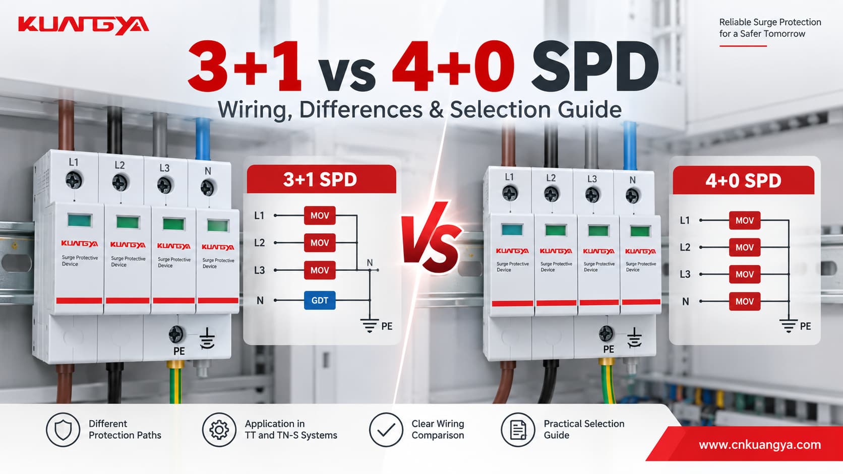
3+1構成と4+0構成のSPDの比較は、外観から始まることがよくあります。どちらもDINレールモジュールを4つ占有する場合、外見上はほぼ同一に見えるためです。.
しかし、電気的な特性は同一ではありません。.
主な違いは、 サージ保護経路です。.
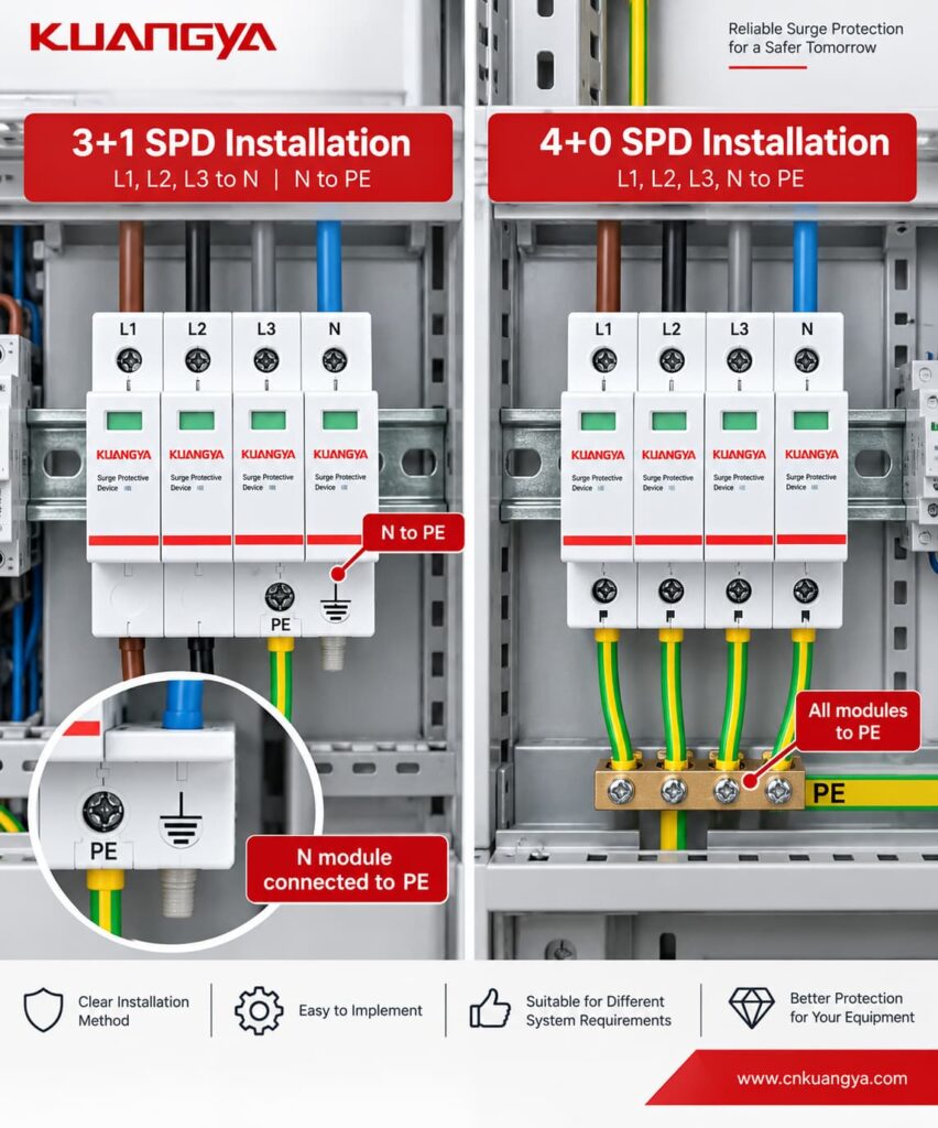
一般的な3+1構成のサージ保護デバイスは、相導体から中性線(N)へ向かう3つの保護経路を使用します。
L1 → N
L2 → N
L3 → N
追加の保護経路が1つ:
N → PE
一般的な4+0構成では、直接PEに基準化された保護経路が提供されます。通常は以下の通りです:
L1 → PE
L2 → PE
L3 → PE
N → PE
この違いは、線間、中性線、保護接地間におけるサージ電圧の制御方法に影響するため、 3+1構成と4+0構成は、モジュール数や極数だけで選択すべきではありません。.
正しい構成は、接地システム、必要な保護モード、設置場所、およびSPDメーカーが規定する実際の内部回路によって決まります。.
クイックアンサー: 3+1はTTシステムで一般的に使用され、TN-Sシステムでも利用可能です。4+0は適切なTN-Sアプリケーションで一般的に使用されます。すべての4極SPDが電気的に同等であると想定せず、必ず配線図と適用される設置要件を確認してください。.
| 特徴 | 3+1 SPD | 4+0 SPD |
|---|---|---|
| 代表的な相保護経路 | L1-N, L2-N, L3-N | L1-PE, L2-PE, L3-PE |
| 中性線保護 | N-PE分離経路 | 4極構成の一部としてのN-PE経路 |
| 標準的な内部設計 | L-N間のMOV + N-PE間のスイッチング素子/GDT | PEを基準とした電圧制限素子(一般的) |
| 直接的なL-N保護 | はい | 専用のL-N要素である必要はない |
| 直接的なL-PE経路 | 協調されたL-N + N-PE経路経由 | はい |
| 一般的な適用 | TTシステムおよび一部のTN-Sシステム | TN-Sシステム |
| 物理モジュール | 4極(4P)が一般的 | 4極(4P)が一般的 |
| 「4P」と同じですか? | 自動的ではありません | 自動的ではありません |
| 選定の主な基準 | 接地方式 + 配線図 + 定格 | 接地方式 + 配線図 + 定格 |
最も重要な点は以下の通りです。
4つのモジュールが見えるからといって、そのSPDが3+1構成か4+0構成かを見分けることはできません。.
必ず結線図を確認してください。.
3+1構成と4+0構成のSPDを選定する鍵は、単に目に見えるモジュールの数を数えることではなく、内部の保護経路を理解することです。.
一般的な三相4線式において 3+1構成のSPD, 3相導体は中性線に対して保護されています。.
保護経路は以下の通りです:
| 保護要素 | 経路 |
|---|---|
| 要素1 | L1 → N |
| 要素2 | L2 → N |
| 要素3 | L3 → N |
| 追加要素 | N → PE |
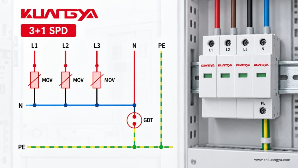
最初の3つの保護素子は、一般的に以下のような電圧制限デバイスです。 MOV(金属酸化物バリスタ).
追加のN-PE間保護素子は、一般的に以下のようなものです。 スパークギャップまたはガス放電管ベースのスイッチング素子, (製品設計によって異なります)。.
例えば、KUANGYAの 3+1タイプ2 AC SPD L1/L2/L3とNの間に3つのMOV保護経路を使用し、NとPEの間にGDT保護経路を組み合わせています。.
ルグラン社も同様に、3P+N / 3+1構成について、L-N間およびN-PE間の保護を提供し、中性極は密閉型放電管によって保護されていると説明しています。.
L1 ──[MOV]──┐
これは簡略化された図です。実際の内部回路および保護技術については、必ずメーカーのデータシートで確認してください。.
典型的な例 4+0 SPD 保護接地(PE)を基準とした4つの保護経路を使用します。.
一般的な構成は以下の通りです:
L1 ──[SPD]── PE
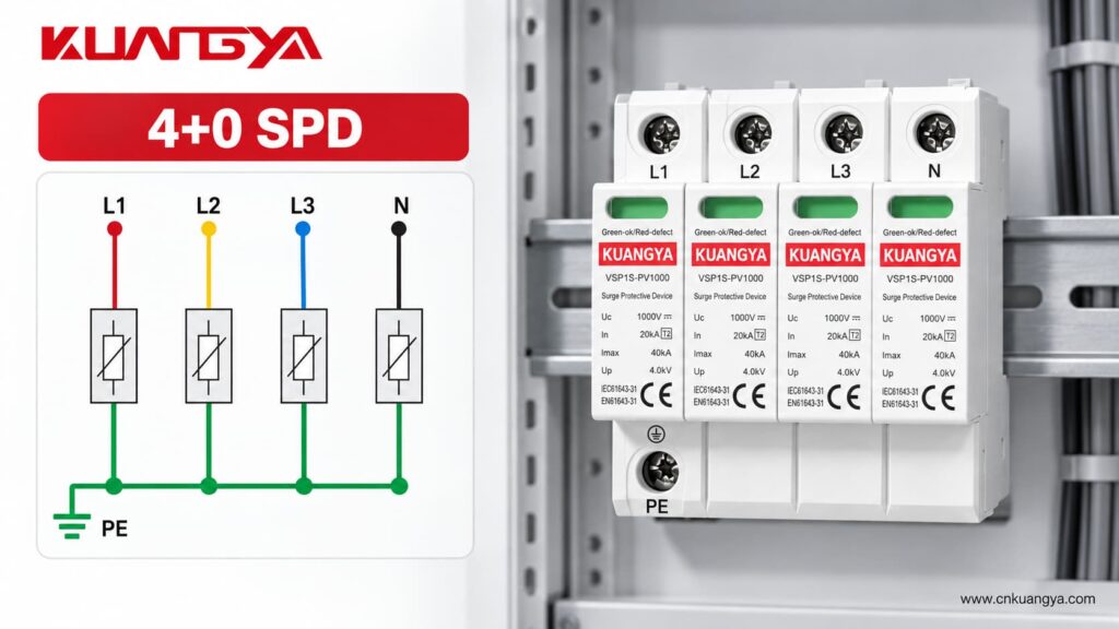
この構成では、3相および中性線のそれぞれがPEに向かう保護経路を有しています。.
例えば、KUANGYA社のVSP1S40 4+0モデルはTN-Sシステム向けであり、L-PEおよびN-PEの保護モードを提供します。.
DEHN社も同様に、4つの経路を持つTN-Sモデルを以下のように定義しています。 4+0構成, 一方で、TTシステムおよびTN-Sシステム向けに、個別の3+1製品も提供しています。.
ただし、この点については購入時に注意が必要です。.
メーカーによって、以下のような用語が使用される場合があります:
4P
3P+N
4+0
3+1
カタログのタイトルにおいて、わずかに異なる方法で使用されることがあります。.
したがって:
製品名だけで内部のSPDトポロジーを判断しないでください。回路図を確認してください。.
本当の違いはモジュールの数ではありません。.
それは サージ電圧がどこで制御され、サージ電流がどこへ逃がされるかという点です。.
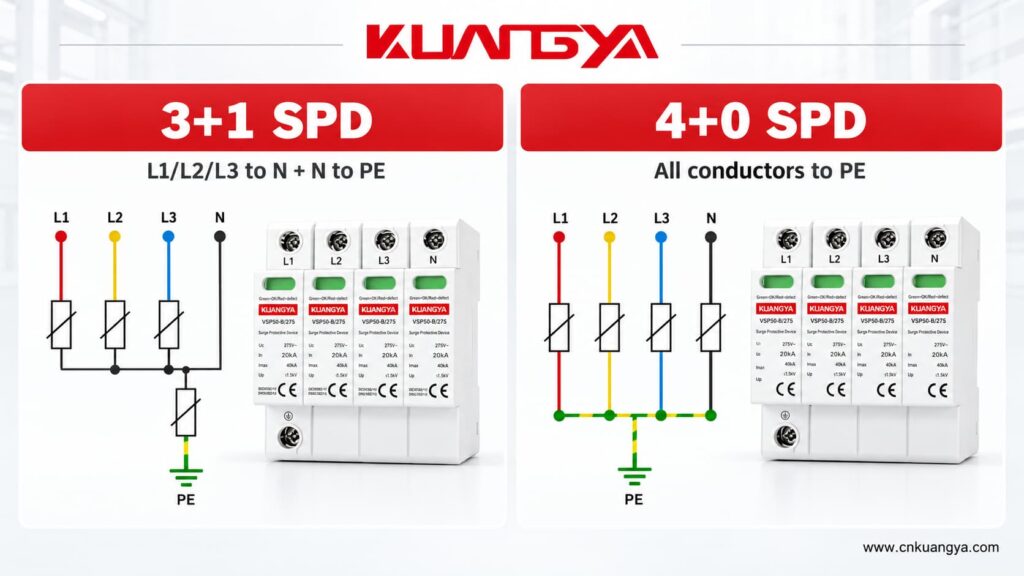
3+1構成は、以下の間を直接保護します:
L1-N間
L2-N間
L3-N間
続いて、以下の間に独立した経路を設けます:
N-PE間
これにより、相と中性線の間に接続された負荷に対して、直接的な線間・中性線間保護を提供します。.
一般的な4+0配置は、活線導体とPE(保護接地)との間に直接的な保護を提供します。
L1-PE
L2-PE
L3-PE
N-PE間
The line-to-neutral voltage may also be influenced during a surge through the combined operation of protection elements, but this is not the same topology as providing a dedicated L-N protective element.
This is why two SPDs with:
can still have very different internal circuits.
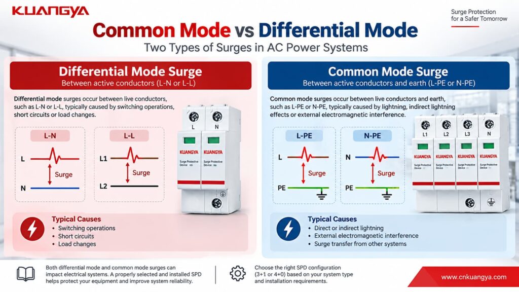
理解する common-mode and differential-mode surge voltage makes the 3+1 vs 4+0 difference easier to understand.
A differential-mode surge appears between active conductors.
例を挙げよう:
L-N
L1-L2
L2-L3
For a single-phase load connected between L and N, the L-N voltage is particularly important.
A typical 3+1 topology provides a direct L-N protective path.
A common-mode surge appears between an active conductor and earth.
例を挙げよう:
L1-PE
L2-PE
L3-PE
N-PE間
Lightning-induced transients can create significant common-mode voltage relative to earth.
A typical 4+0 configuration provides direct active-conductor-to-PE paths.
A 3+1 configuration handles the surge through its coordinated L-N and N-PE protection network.
Therefore, when comparing SPDs, asking:
“How many poles does it have?”
is less useful than asking:
“Which protection modes does it provide?”
This is one of the most important differences buyers notice when opening a 3+1 SPD.
The N-PE module may look different from the three L-N modules.
That is not necessarily a manufacturing inconsistency.
It may use a different protection technology because it performs a different electrical function.
In many 3+1 designs:
L-N = MOV
while:
N-PE = GDT or spark-gap-based element
DEHN, for example, offers dedicated N-PE spark-gap arresters intended for 1+1 and 3+1 configurations in TT systems.
KUANGYA’s Type 2 3+1 AC SPD similarly uses MOV protection between the phases and neutral, with a GDT between neutral and PE.
One advantage of a suitable switching N-PE element is that it does not create the same continuous leakage path between N and PE as a permanently voltage-limiting element might.
However, the exact technology, follow-current capability, TOV behavior and ratings remain product-specific.
Never assume that every 3+1 SPD uses exactly the same internal components.
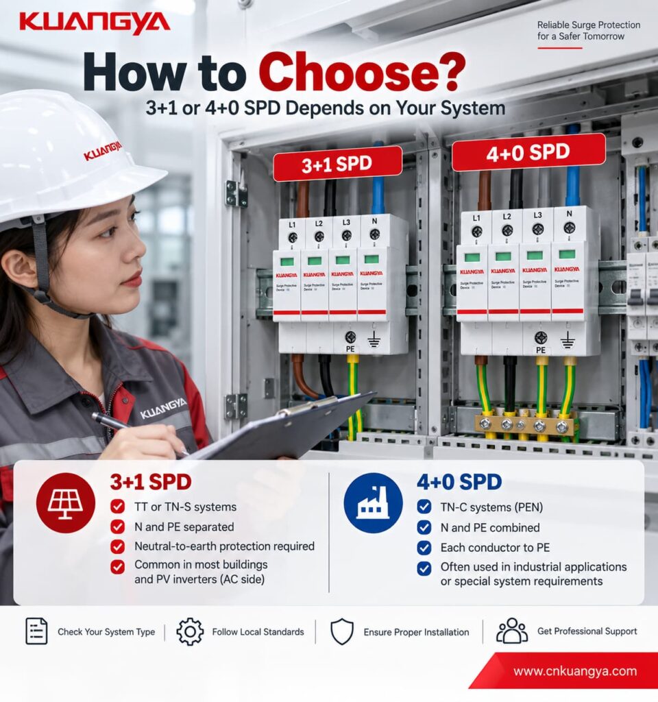
For 3+1 vs 4+0 SPD selection, the earthing system is one of the most important factors to confirm. For a typical IEC-based TT earthing system, a 3+1 configuration is widely used.
In a TT system:
A 3+1 SPD provides:
L1 → N
L2 → N
L3 → N
plus:
N → PE
This topology is commonly used to coordinate surge protection with the TT earthing arrangement.
DEHN’s technical guidance shows the 3+1 circuit for TT systems, and current DEHN products are specifically offered for TT and TN-S installations using this configuration.
It is tempting to remember:
TT = 3+1
That is useful as a starting point, but it is not a complete SPD specification.
You must still check:
TN-S systems have separate:
N — Neutral
そして
PE — Protective Earth
conductors.
Both 3+1 and suitable 4+0 products can be found for TN-S applications.
For example, DEHN currently offers:
4+0 products specifically for TN-S
そして:
3+1 products for TT and TN-S systems.
KUANGYA follows a similar product distinction: the VSP1S40 4+0 version is specified for TN-S, while the corresponding 3+1 configuration is available for TT and TN-S systems.
Therefore, it is not technically correct to say:
“TN-S always needs 4+0.”
または:
“3+1 is only for TT.”
Instead, the required protection modes, installation rules and manufacturer-approved configuration should determine the selection.
This is where pole-count mistakes become particularly common.
In a TN-C section of an installation, neutral and protective-earth functions are combined in a single:
PEN conductor
A typical three-phase arrangement therefore uses:
L1-PEN
L2-PEN
L3-PEN
often described as a 3+0 configuration.
There is no separate N conductor and PE conductor at that point, so a separate N-PE protection path would not describe the conductor arrangement correctly.
A TN-C-S installation contains two different sections.
Before the PEN conductor is separated:
TN-C principles apply.
After PEN is separated into:
N + PE
the downstream section behaves as TN-S.
したがって:
The correct SPD configuration depends on where the SPD is installed relative to the PEN separation point.
Do not select a 3P or 4P SPD simply because the overall building supply is described as TN-C-S.
Check the actual conductor arrangement at the SPD installation point.
The easiest way to identify a 3+1 vs 4+0 SPD configuration is to check the manufacturer’s wiring diagram rather than count the cartridges.
Look at the wiring diagram.
L1 ── SPD ── N
L2 ── SPD ── N
L3 ── SPD ── N
N  ── SPD ── PE
Look for three phase-to-neutral paths plus one neutral-to-earth path.
The N-PE element may also have a different symbol from the L-N elements.
L1 ── SPD ── PE
L2 ── SPD ── PE
L3 ── SPD ── PE
N  ── SPD ── PE
Look for four protection paths referenced toward PE.
When requesting a quotation, do not write only:
“Need 4P SPD.”
Instead, provide:
システム: AC230/400 V
Earthing system: TT / TN-S / TN-C / TN-C-S
Required SPD type: Type 1 / Type 2 / Type 1+2
Topology: 3+1 / 4+0 if known
Uc: required value
In / Imax / Iimp: required values
Remote signal: はい/いいえ
This greatly reduces the chance of receiving a product with the correct number of modules but the wrong internal connection.
Neither topology is universally “better.”
They solve surge-protection paths differently.
A correctly selected 4+0 SPD can be appropriate for a suitable TN-S application.
A correctly selected 3+1 SPD can be appropriate for TT and suitable TN-S applications.
The important question is not:
Which one is stronger?
正しくは次の通りです。
Which topology matches the electrical network and the protection modes required at this installation point?
Performance must then be evaluated using the actual electrical specifications.
これらには次のようなものがある:
| パラメータ | What to check |
|---|---|
| ウク | 最大連続使用電圧 |
| 上へ | 電圧保護レベル |
| で | 公称放電電流 |
| アイマックス | Maximum discharge current for applicable Type 2 products |
| インプ | Lightning impulse current for applicable Type 1 products |
| Isccr / short-circuit rating | Compatibility with available fault current |
| Backup protection | Required fuse or circuit breaker |
| TOV performance | Behavior under temporary overvoltage |
| Remote contact | Whether remote monitoring is required |
Do not judge SPD performance simply by the largest kA number on the label.
そうだ。.
This is an easy naming mistake.
3+1 describes the SPD protection topology.
It does not mean:
Type 3 + Type 1.
If you are unsure about the difference between SPD classifications, see our guide to Type 1, Type 2 and Type 3 SPDs.
SPD classification and topology are separate characteristics.
AC power SPDs are covered by IEC 61643-11, which specifies performance and safety requirements, tests and ratings for surge protective devices connected to AC low-voltage power systems.
For example, a 3+1 SPD may be:
タイプ1
タイプ2
または
タイプ1+2
depending on its tested performance.
Likewise, a 4+0 product can also be offered in different SPD Types.
したがって:
3+1 tells you how the protection paths are arranged. Type 1, Type 2 and Type 1+2 tell you about the SPD’s test classification and surge-current duty.
Not automatically.
Even if both products have:
their protection modes can be different.
Before replacing one topology with another, verify:
The replacement should be based on the complete electrical design, not only mechanical compatibility.
Circuit breakers and SPDs should not be interpreted in exactly the same way.
A four-pole circuit breaker normally refers to conductors passing through switching/protection poles.
An SPD generally works in parallel with the circuit and provides a temporary low-impedance surge path.
So “four-pole SPD” does not automatically tell you everything about:
If you are unfamiliar with this difference, see our guide なぜSPDは直列ではなく並列に接続されるのか?
The circuit diagram remains more important than the number of visible modules.
Four cartridges do not automatically mean a particular topology.
Check the internal diagram.
A four-module product can use different internal protection arrangements.
“4P” and “3+1” should not be treated as synonyms without checking the manufacturer’s circuit.
3+1 products are widely used for TT, but manufacturers such as DEHN and KUANGYA also specify certain 3+1 products for TN-S systems.
The network arrangement before and after the PEN separation point is different.
Confirm where the SPD will actually be installed.
A 40 kA SPD is not automatically more suitable than a 20 kA product simply because the number is larger.
Topology, SPD Type, Uc, Up, In, Iimp, fault-current conditions and coordination must all be considered.
The SPD’s surge-current rating is not the same thing as the rating of its backup fuse or circuit breaker.
Do not calculate:
Imax 40 kA = 40 A backup fuse.
That is incorrect.
Backup protection must be selected according to the manufacturer requirements and the installation’s overcurrent and prospective short-circuit conditions.
For a detailed explanation, see our guide SPDバックアップヒューズ:適切な選定のための7つのルール.
SPD selection and installation should also follow applicable requirements such as IEC 60364-5-53 and local electrical regulations.
During a fast surge event, conductor inductance creates additional voltage.
Long or looped connecting wires can therefore increase the effective voltage reaching the protected equipment.
Use the shortest practical routing permitted by the installation design and applicable requirements.
Never create an unauthorized N-PE connection simply to make SPD wiring easier.
This is particularly important in TT and TN-C-S systems.
The neutral, PE and PEN arrangement is part of the earthing system itself.
The SPD manufacturer may specify:
Follow the product data rather than estimating the backup device from In or Imax.
In installations containing RCDs or RCCBs, SPD location and topology can affect the current path during transient or fault conditions.
TT systems require particular attention to the relationship among:
SPD + RCD + N + PE
Follow the applicable installation rules and manufacturer guidance.
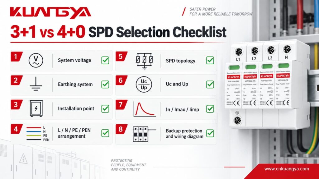
Before ordering or approving an AC SPD, confirm the following:
| チェック | 質問 |
|---|---|
| システム電圧 | Is it 230/400 V, 120/208 V or another system? |
| 頻度 | 50 Hz or 60 Hz? |
| 接地方式 | TT, TN-S, TN-C, TN-C-S or IT? |
| Installation point | Before or after the PEN split? |
| ニュートラル | Is N distributed at the SPD location? |
| PE/PEN | Is the protective conductor PE or PEN? |
| トポロジー | 3+0, 4+0, 3+1 or another configuration? |
| 保護モード | L-N, L-PE, N-PE and/or L-L? |
| SPDタイプ | Type 1, Type 2 or Type 1+2? |
| ウク | Is the maximum continuous voltage suitable? |
| 上へ | Is the protection level suitable for downstream equipment? |
| イン / アイマックス | Are the Type 2 discharge ratings suitable? |
| インプ | If Type 1 is required, is Iimp specified? |
| Short-circuit rating | Is the SPD compatible with available fault current? |
| Backup device | Is the required fuse/MCB confirmed? |
| TOV | Is temporary-overvoltage behavior specified? |
| Remote signal | Is remote monitoring required? |
| Wiring diagram | Has the actual manufacturer circuit been checked? |
A buyer who completes this checklist is much less likely to purchase the wrong SPD simply because two products look similar.
Consider two Type 2 AC SPDs.
Internal paths:
L1-N
L2-N
L3-N
N-PE
Internal paths:
L1-PE
L2-PE
L3-PE
N-PE
From the front, these two devices may appear very similar.
Their surge-current ratings may even be identical.
But their protection topology is different.
That is why:
Same voltage + same kA + same number of modules does not mean the SPDs are electrically interchangeable.
KUANGYA offers a range of ACサージ保護デバイス for different low-voltage distribution systems.
For example, the VSP1S40 Type 2 series includes:
| 構成 | Typical network application | Protection arrangement |
|---|---|---|
| 3+0 | TN-C | L-PEN |
| 4+0 | TN-S | L-PE / N-PE |
| 1+1 | TT / TN-S single phase | L-N + N-PE |
| 3+1 | TT / TN-S three phase | L1/L2/L3-N + N-PE |
The 3+1 design uses high-energy MOV elements for the L-N paths together with a GDT in the N-PE path, while the 4+0 version uses a different protection arrangement suited to its declared network application.
When requesting a model, provide the actual:
network voltage + earthing system + SPD Type + required surge ratings + remote contact requirement
rather than ordering only by the number of poles.
Physically, a 3+1 SPD may use four positions or modules, but “3+1” describes the protection topology rather than merely the mechanical pole count.
Check the product wiring diagram.
Not universally.
The correct choice depends on the earthing system, required protection modes, installation rules and product design.
A correctly selected 4+0 device can be suitable for TN-S applications, while 3+1 is widely used in TT and also in suitable TN-S systems.
In many 3+1 designs, the three phase-to-neutral protection elements use MOV technology, while the N-PE path uses a GDT or spark gap.
The fourth module therefore performs a different electrical function.
Potentially, yes.
Manufacturers including DEHN and KUANGYA offer 3+1 products declared for TT and TN-S applications. Final selection should still follow the product datasheet and applicable installation requirements.
Do not assume that a generic 4+0 product is suitable.
TT systems require careful consideration of the protection arrangement, N-PE path, RCD location and applicable installation requirements.
Use an SPD specifically declared by the manufacturer for the intended TT configuration.
そうだ。.
3+1 is a connection topology.
Type 1, Type 2 and Type 3 are SPD classifications associated with different test and application requirements.
They are separate concepts.
そうだ。.
Manufacturers may use terms such as 4P, 3P+N, 3+1 and 4+0 differently in short product descriptions.
Always verify the internal wiring diagram and declared protection modes.
Start with the earthing system and actual conductor arrangement at the installation point.
Then check:
protection topology → SPD Type → Uc → Up → surge-current ratings → short-circuit conditions → backup protection → installation requirements.
Do not start with the largest kA value.
The most important point in a 3+1 vs 4+0 SPD comparison is that the difference is not simply the number of modules.
A typical 3+1 SPD provides three phase-to-neutral protection paths plus a separate neutral-to-earth path:
L1-N + L2-N + L3-N + N-PE
A typical 4+0 SPD instead provides four protection paths referenced toward PE:
L1-PE + L2-PE + L3-PE + N-PE
3+1 is widely used in TT systems and can also be used in suitable TN-S applications. 4+0 is commonly available for TN-S systems.
However, the earthing system alone is not the complete specification.
Before selecting an SPD, verify the actual wiring diagram, protection modes, Uc, Up, In, Imax or Iimp, short-circuit conditions, backup protection and manufacturer installation requirements.
The most useful rule is simple:
Do not choose an SPD by counting modules. Choose it by checking the network, protection paths and electrical ratings.
Technical references used to verify the concepts in this guide include:
IEC/EN 61643-11 — Low-voltage surge protective devices for AC power systems.
IEC 60364-5-53 — Selection and erection of electrical equipment, including SPD connection and application principles.
デーン — Technical documentation for 3+1 TT/TN-S and 4+0 TN-S surge arrester configurations.
ルグラン — Technical documentation identifying 3P+N / 3+1 L-N and N-PE protection modes.
クアンニャ — VSP1S40 Type 2 AC SPD technical data and internal connection configurations.

