温州市岳陽工業区 325000
勤務時間
月曜日~金曜日:午前7時~午後7時
週末午前10時~午後5時
温州市岳陽工業区 325000
勤務時間
月曜日~金曜日:午前7時~午後7時
週末午前10時~午後5時

サージ防護デバイス(SPD)は電気機器を過渡過電圧から保護しますが、SPD自体に内部故障や短絡が発生した場合、何がSPDを保護するのでしょうか?
ここで重要となるのが、 SPDバックアップ用ヒューズまたは配線用遮断器です。 しかし、「すべてのタイプ2 SPDには125Aのヒューズが必要である」といった普遍的なルールは存在しません。.
However, there is no universal rule such as:
“Every Type 2 SPD needs a 125 A fuse.”
または:
“「40 kAのSPDには40 Aのブレーカーを使用すべきである。」”
どちらの記述も誤りである可能性がある。.
正しい SPDバックアップヒューズ 選定は、特定のSPDモデル、上流側の過電流保護、想定短絡電流、導体サイズ、システム構成、およびメーカーの指示に依存する。.
一部のSPDは既存の上流側ヒューズや回路遮断器を使用できる。一方で、個別のバックアップ保護を必要とするものもある。製品によっては、バックアップ保護をSPD内部に統合しているものさえある。.
したがって、最も重要なルールは単純である:
SPDのIn、Imax、またはタイプ分類のみに基づいてSPDバックアップヒューズを選定してはならない。必ずメーカーが規定するバックアップ保護と、実際の設置条件を確認すること。.
SPDにはバックアップヒューズや回路遮断器が必要な場合がありますが、すべての設置において個別の保護機器が必要なわけではありません。.
既存の上位過電流保護装置がSPDメーカーの許容する保護構成を満たしている場合、追加のバックアップヒューズは不要な場合があります。.
上位の保護装置がメーカーの許容値を超えている場合、またはSPDの指示書で専用の分岐保護が指定されている場合は、追加の SPDバックアップ用ヒューズまたは配線用遮断器です。 保護装置が必要になることがあります。.
つまり、正しい問いは単に次のようなものではありません。
“「どのサイズのヒューズを取り付けるべきか?」”
代わりに、次のように問いかけてください。
“既存の上流側保護機器は、このSPDの要件を正確に満たしていますか?”
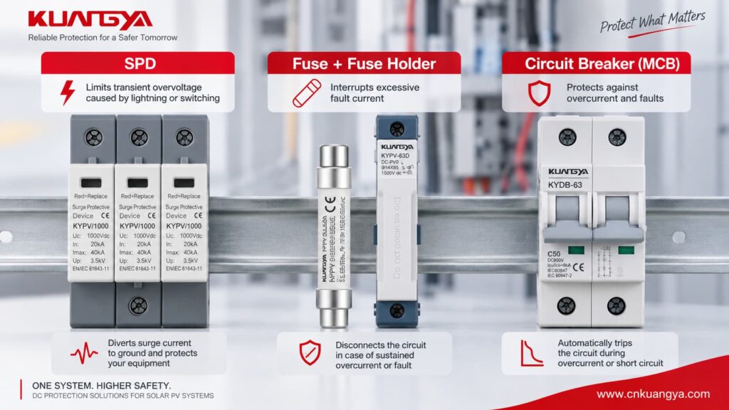
SPDと過電流保護装置は、それぞれ異なる電気的問題を解決するものです。.
一般的な電源用SPDは、回路に対して並列に接続されます。.
通常動作時、SPDには負荷電流がほとんど、あるいは全く流れません。過渡過電圧が発生すると、SPDは導通状態となり、設計された保護経路を通じてサージ電流を逃がします。.
ヒューズや回路遮断器(ブレーカー)は、それとは異なる目的を持っています。.
主な役割は、持続的な過電流または故障電流を遮断することです。.
| 装置 | 主な機能 | 主な設計用途 |
|---|---|---|
| SPD | 過渡過電圧を制限し、サージ電流を逃がす | 雷および開閉サージ |
| ヒューズ | 過大な電流を遮断する | 過電流および短絡 |
| 配線用遮断器 | 過大な電流を遮断し、絶縁/開閉機能を提供する | 過負荷および短絡 |
| 内部SPD断路器 | 故障または過熱した保護素子を切り離します | SPDの寿命終了または内部異常状態 |
したがって:
SPD ≠ ヒューズ
そして:
ヒューズ ≠ SPD
これらは補完的な保護を提供します。.
多くの電圧制限型SPDは、酸化亜鉛バリスタのような非線形素子を使用しています。.
通常のシステム電圧下では、保護素子は高インピーダンス状態を維持します。.
サージ発生時、その電気的特性は急速に変化し、サージ電流を導通させます。.
しかし、サージ保護素子は最終的に寿命に達するか、あるいは以下のような原因で損傷する可能性があります。
保護素子で低インピーダンス故障が発生した場合、設備は発生する商用周波数または直流の故障電流を安全に遮断できなければならない。.
これが、SPDのデータシートに以下のようなパラメータが含まれる理由である。
交流低圧SPDに関する現在の国際製品規格は、 IEC 61643-11:2025, であり、1,000V RMS以下の交流回路に接続されるSPDの要件および試験方法を規定しています。.
IEC 61643-11:2025 — IEC公式ページ
よくある質問は以下の通りです:
“「SPDに内蔵の遮断器が既に備わっている場合、なぜ別のヒューズが必要なのですか?」”
それらは必ずしも同じ機能を果たすわけではないからです。.
内蔵遮断器は、一般的にSPD内部のサージ保護素子に関連付けられています。.
例えば、MOV(酸化亜鉛素子)が危険な熱状態に達した際、内蔵メカニズムが故障した素子を切り離すことができます。.
多くのモジュール式SPDでは、この状態が機械的にステータスインジケーターと連動しています。.
メーカーの設計により、表示窓が緑色から赤色に変わる場合があります。.
外部ヒューズまたは回路遮断器は、設備の故障電流保護および協調の一部を構成します。.
SPDの種類に応じて、以下の役割を果たすことができます:
したがって:
内部の熱分離器は、外部SPDバックアップヒューズの代替品として自動的に見なされるべきではありません。.
製品ドキュメントを必ず確認する必要があります。.
そうだ。.
一般的な状況は3つあります。.
| Installation Condition | Separate Backup Protection |
|---|---|
| Existing upstream device is within the SPD manufacturer’s permitted conditions | Often not required |
| Existing upstream device exceeds the manufacturer’s permitted limit | Dedicated protection may be required |
| SPD has tested integrated backup protection | Additional backup device may not be required within specified conditions |
This is one of the most important points in SPD backup protection.
You cannot make the decision using only:
Two Type 2 SPDs with similar voltage and Imax ratings may have different backup-protection requirements.
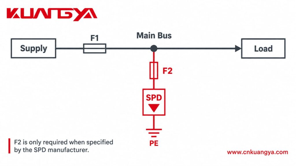
SPD installation diagrams often use two designations:
F1 = upstream system protective device
F2 = dedicated SPD backup protective device
A simplified arrangement may look like:
Supply → F1 → Distribution System
with the SPD connected in parallel through F2 where dedicated F2 protection is required.
When selecting an SPDバックアップヒューズ, the first question should therefore not be:
“What size fuse should I buy?”
Instead ask:
“Can the existing F1 already provide the protection required by this SPD?”
If F1 meets the manufacturer’s conditions, F2 may not be necessary.
If F1 is larger than the permitted value, a dedicated F2 may be needed.
This principle is demonstrated clearly in several manufacturer’s published installation guides, which we will examine later.
There is no universal SPDバックアップヒューズ size.
Always start with the exact manufacturer’s datasheet or installation instructions.
Look for wording such as:
Do not take a fuse value from another SPD simply because both devices are Type 2 or both have Imax = 40 kA.
Product construction and tested coordination can be different.
Suppose an SPD manufacturer allows:
Maximum upstream protection = 125 A gG
and the system already has:
F1 = 63 A gG
If all other manufacturer requirements are satisfied, the existing upstream fuse may already provide the necessary protection.
Installing another 125 A fuse does not automatically make the installation safer.
Now consider:
F1 = 250 A gG
If the SPD is only approved with a maximum 125 A gG backup arrangement, the existing 250 A protection may no longer satisfy the SPD requirements.
A dedicated SPDバックアップヒューズ may then be necessary.
This is why F1 must be checked before adding F2.
Fuse ampere rating alone is not enough.
You must also consider the available fault current at the installation point.
The same SPD can face very different fault conditions depending on where it is installed.
例えば、こうだ:
A small downstream distribution board may have relatively low prospective short-circuit current.
A main industrial panel close to a transformer can have significantly higher available fault current.
Therefore, always evaluate the combination of:
SPD + backup protection + available short-circuit current
This is especially important in:
Consider a Type 2 SPD marked:
In = 20 kA
Imax = 40 kA
A very common mistake is:
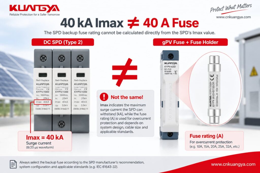
“The SPD is 40 kA, so it should use a 40 A fuse.”
That is incorrect.
Imax = 40 kA describes a surge-current characteristic associated with the relevant impulse waveform.
A 40 A fuse is an overcurrent protective device rating.
These values describe different electrical phenomena.
したがって:
The SPD backup fuse rating cannot be calculated directly from the SPD’s Imax value.
If you are unsure about the difference between In, Imax, Up and Iscpv, see our DC SPD仕様ガイドをご参照ください.
Understanding these parameters prevents one of the most common SPD selection errors.
The manufacturer’s maximum backup-fuse value does not mean that the largest permitted fuse should always be installed.
The protective device must also coordinate with:
For example, if an SPD permits a maximum backup fuse of 125 A, that does not automatically mean every installation should use a 125 A fuse.
Maximum is a limit, not always a recommendation.
A fuse and a circuit breaker can both provide overcurrent protection, but their operating characteristics are different.
| ファクター | ヒューズ | サーキットブレーカー |
|---|---|---|
| Replacement after operation | Must normally be replaced | Can normally be reset after investigation |
| Time-current behavior | Depends on fuse class and rating | Depends on breaker type and trip curve |
| Short-circuit capability | Can be very high | Depends on breaker breaking capacity |
| Surge impulse behavior | Depends on fuse characteristics | Depends on breaker characteristics |
| Isolation | Requires suitable holder/switching arrangement | Often convenient |
| コーディネーション | Must match SPD data | Must match SPD data |
したがって:
Do not assume that a 125 A gG fuse can automatically be replaced by a 125 A circuit breaker.
Manufacturers can specify different protective-device combinations.
For example, Schneider Electric publishes coordination tables pairing particular SPD models with specific protective-device ratings rather than applying one universal breaker value.
Do not copy an AC SPD backup-protection rule directly into a photovoltaic DC system.
PV systems have different:
SPDs designed specifically for the DC side of photovoltaic installations are covered by IEC 61643-31:2018, which applies to PV DC SPDs up to 1,500 V DC.
IEC 61643-31:2018 — official IEC page
This is why an AC SPD backup-fuse example should never automatically be applied to a 1,000 V or 1,500 V PV system.
The following SPD backup fuse examples come from published manufacturer technical information.
They are useful because they demonstrate that backup-protection requirements vary significantly between products.
Do not copy these values to another SPD without checking its own datasheet.
| Manufacturer Example | Published Information | What It Demonstrates |
|---|---|---|
| Schneider Electric Resi MAX | Backup fuse only required if not already provided in mains; published table shows no F2 required in one F1 ≤125 A / Isc <50 kA arrangement | Existing upstream protection may sometimes provide the required backup protection |
| Phoenix Contact VAL-SEC | Published guidance allows installation without additional F2 up to specified upstream conditions; if dedicated F2 is used, 125 A gG is recommended in the example | F2 is not automatically required |
| DEHNguard SE CI | Integrated backup fuse; manufacturer states no additional backup fuse required up to its specified 25 kArms short-circuit condition | Backup protection can be integrated into the SPD |
Let’s look at these examples more closely.
Schneider Electric’s Resi MAX installation instructions provide an especially useful example.
For the documented SPD arrangement, Schneider states that the backup fuse is:
required only if suitable protection is not already provided in the mains.
The document lists ≤125 A gL/gG backup protection and shows a case where:
F1 ≤125 A
そして:
Isc <50 kA
can result in:
No need for F2
under the manufacturer’s stated conditions.
Schneider Electric Resi MAX SPD installation instructions
This is an excellent example of why installing an additional fuse automatically is not always correct.
Phoenix Contact provides a useful Type 2 SPD backup-fuse example for its VAL-SEC range.
Its published technical guidance explains that the device can be installed in the branch line without an additional F2 under specified upstream protection conditions.
Where a dedicated F2 is nevertheless required or desired, the document gives:
125 A gG
as an appropriate value for the example.
More importantly, Phoenix Contact also warns against selecting certain smaller backup fuses below 80 A gG in that specific arrangement because their impulse withstand may result in unwanted operation during surge events.
Phoenix Contact — The Right Backup Fuse for Surge Protective Devices
これは~を行います ない mean that every Type 2 SPD needs an 80 A or 125 A fuse.
It demonstrates something more important:
An SPD backup fuse must be coordinated with the specific SPD. Choosing the smallest possible fuse is not automatically the safest option.
Not every SPD requires an external backup fuse.
DEHN’s DEHNguard SE CI Type 2 SPD includes an integrated backup fuse.
DEHN states that no additional backup fuse is required for installations within the product’s specified maximum short-circuit current of 25 kArms.
DEHNguard SE CI with integrated backup fuse
This example shows why the statement:
“Every SPD must have a separate external fuse.”
is incorrect.
The correct arrangement depends on the tested product design.
そうだ。.
A smaller fuse is not automatically safer.
The protective device must be capable of remaining intact during the surge conditions that the SPD is intended to handle while still interrupting a sustained fault when required.
If an undersized fuse operates unnecessarily during a surge, the SPD can become disconnected.
The electrical installation may then continue operating normally while surge protection has been lost.
This can be particularly difficult to notice in a parallel-connected SPD.
Phoenix Contact’s published example illustrates this issue by warning against certain undersized gG backup fuses in the specific Type 2 SPD arrangement described above.
Again:
This is a product-specific example, not a universal minimum fuse value.
そうだ。.
If the external protective device exceeds the maximum value permitted by the SPD manufacturer, the SPD may no longer be operating within the tested fault-protection arrangement.
For example, if a product states:
Maximum backup fuse: 125 A gG
this should not be interpreted as:
“125 A must always be installed.”
Instead it means that the protection arrangement should not exceed the manufacturer’s stated limit unless another approved configuration is provided.
The actual selection must still consider:
Consider a Type 2 SPD in a small commercial distribution board.
Assume:
Main upstream fuse F1 = 63 A gG
and the selected SPD permits:
Maximum upstream protection = 125 A gG
If:
then the existing 63 A upstream device may already provide the required backup protection.
Adding a second 125 A fuse would not automatically improve the system.
Now consider a larger industrial panel.
Assume:
F1 = 400 A
while the SPD permits:
Maximum backup protection = 125 A gG
The upstream protection now exceeds the manufacturer’s stated limit.
A dedicated F2 may therefore be required.
The simplified arrangement may become:
400 A upstream protection → SPD branch → approved F2 → SPD
However, the designer must still verify:
This is why a backup-protection arrangement that works in a small distribution board cannot simply be copied into an industrial main panel.
Photovoltaic DC systems require additional care.
A PV DC SPD must be suitable for:
The exact SPDバックアップヒューズ arrangement can depend on:
Before choosing backup protection, the SPD voltage itself must also be correct.
For more detail, see our DC SPD voltage selection guide for solar PV systems.
そうだ。.
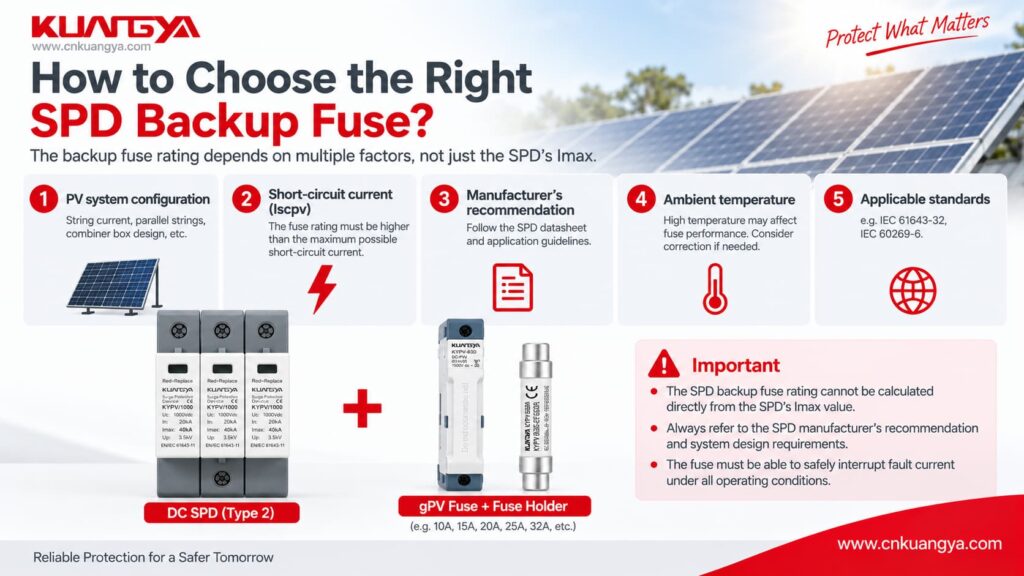
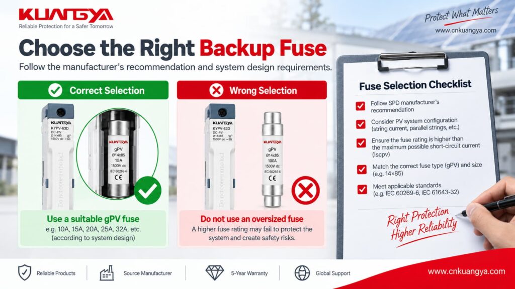
A gPV fuse is specifically designed for photovoltaic applications, but this does ない mean every PV SPD requires a separate gPV backup fuse.
The manufacturer’s instructions must be checked first.
Depending on the system design, existing PV overcurrent protection may already form part of the approved protection arrangement.
If a gPV fuse is required, it must also be suitable for:
For examples of PV-rated fuse links and holders, see KUANGYA’s DC gPV fuse range.
The product page is useful for understanding available PV fuse formats, but final SPD coordination must still follow the SPD manufacturer’s technical data.
Where dedicated backup protection is required, it is normally positioned in the SPD branch so that fault current flowing to the SPD can be interrupted.
A simplified concept is:
Busbar / Supply → F2 → SPD → required protection path
However, the exact wiring depends on:
Always follow the wiring diagram for the exact SPD.
Adding a fuse or breaker should not result in unnecessarily long SPD connections.
SPD connection conductors have inductance.
During a fast-rising surge current, additional lead length can increase the voltage appearing across the protected equipment.
This means backup protection should be coordinated while keeping the SPD connection path short and direct.
For PV systems, there is also another distance issue: the distance between the SPD location and the inverter.
These two distances should not be confused.
For a detailed explanation, see our guide to SPD distance from inverter and SPD connection lead length.
Sometimes.
The existing protective device may be acceptable if:
However, a dedicated SPD breaker can also provide practical advantages such as easier isolation and maintenance.
重要な点は以下の通りです。
Dedicated protection does not automatically mean correctly coordinated protection.
The device must still match the SPD manufacturer’s requirements.
Because many power SPDs are connected in parallel, the main electrical load can continue operating even after the SPD branch is disconnected.
That means:
Power ON does not necessarily mean surge protection ON.
If the backup fuse opens, the cause should be investigated rather than simply replacing the fuse and re-energizing the system.
考えられる原因は以下の通り:
If you suspect the SPD itself has failed, see our guide on SPDの故障を見分ける方法.
| 間違い | Why It Is Wrong |
|---|---|
| 40 kA SPD = 40 A fuse | Imax and fuse current rating describe completely different electrical quantities |
| Every Type 2 SPD needs 125 A | Backup protection is manufacturer-specific |
| Smaller fuse is always safer | It may disconnect unnecessarily during surge events |
| Internal SPD disconnector means no external protection is ever required | Internal and external protective functions are not necessarily identical |
| 125 A fuse = 125 A breaker | Fuse and breaker operating characteristics differ |
| F2 must always be installed | Existing F1 may already meet the SPD requirement |
| Ignore prospective short-circuit current | SPD protection must be coordinated with available fault current |
| Use AC examples for PV DC SPD | AC and PV DC systems have different requirements |
| Choose only by Imax | Imax does not determine backup-fuse rating |
| Use maximum permitted fuse automatically | “Maximum” is a limit, not necessarily the ideal rating |
Before selecting an SPDバックアップ用ヒューズまたは配線用遮断器です。, check the following:
| チェック | 質問 |
|---|---|
| Exact SPD | What manufacturer and model is installed? |
| 申し込み | AC or photovoltaic DC? |
| SPDタイプ | Type 1, Type 1+2 or Type 2? |
| 電圧 | Are Uc/Ucpv suitable for the system? |
| Upstream device | What is F1? |
| Manufacturer limit | What maximum backup protection is specified? |
| Dedicated F2 | Is it actually required? |
| Fault current | What is the prospective short-circuit current? |
| Fuse class | gG, gPV or another specified type? |
| 配線用遮断器 | What curve and breaking capacity are required? |
| Conductors | Is the conductor cross-section suitable? |
| ターミナル | Can the SPD terminals accept the selected conductors? |
| Lead length | Are SPD connection leads short and direct? |
| Earthing | Is the protection path correctly connected? |
| Indication | Can failure or disconnection be detected? |
If several of these answers are unknown, selecting a backup fuse by guesswork is not appropriate.
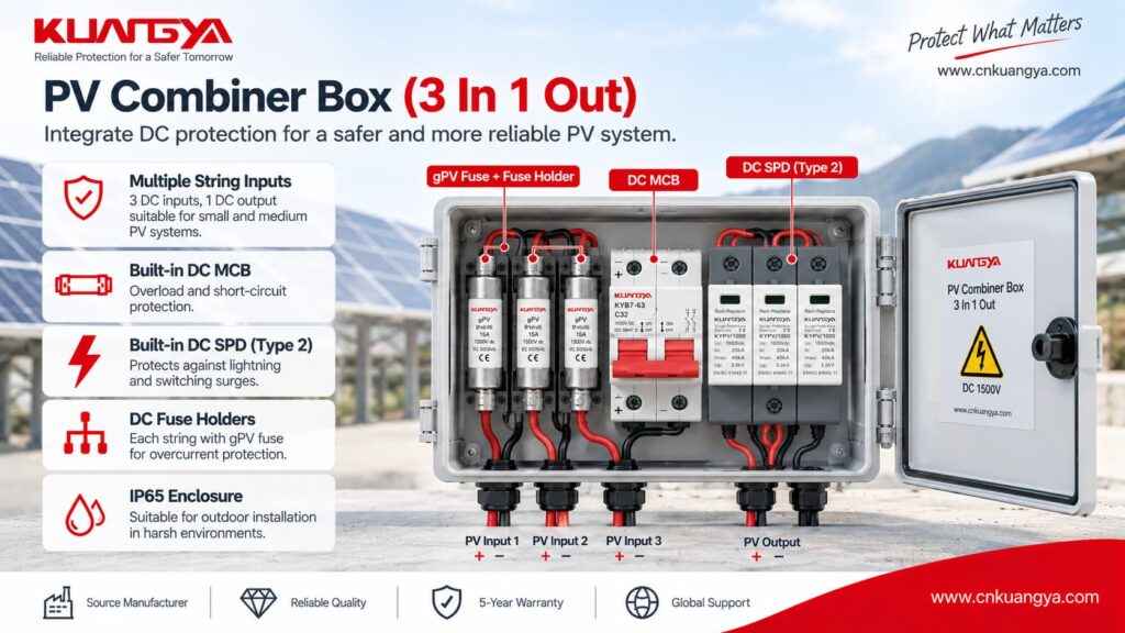
IEC 61643-11 covers SPDs intended for connection to AC low-voltage power circuits and specifies performance and safety requirements, tests and ratings.
IEC 61643-31 applies specifically to SPDs intended for the DC side of photovoltaic installations up to 1,500 V DC.
IEC 60364-5-53 covers the selection and erection of electrical equipment for protection, isolation, switching, control and monitoring.
The current IEC consolidated version includes the 2019 base publication plus amendments from 2020 and 2024.
IEC 60364-5-53:2019+A1:2020+A2:2024
Applicable national standards, installation rules and manufacturer instructions must also be followed.
そうだ。.
A separate SPDバックアップヒューズ is not always necessary.
If the existing upstream protective device already satisfies the manufacturer’s permitted backup-protection conditions, another fuse may not be required.
Some SPDs also include integrated backup protection.
There is no universal fuse size for an SPD.
Use the exact SPD datasheet and check:
Do not calculate the fuse size from Imax alone.
そうだ。.
125 A appears in several manufacturer examples, but it is not a universal Type 2 SPD value.
Published examples show SPDs with different arrangements, including:
Sometimes.
But the circuit breaker’s:
must be suitable.
Do not replace a specified fuse with a breaker simply because both devices have the same ampere rating.
必ずしもそうではない。.
A red status indicator commonly relates to the condition of the SPD’s internal protection module or disconnection mechanism.
An external backup fuse is a separate protective device.
Therefore, both the SPD status and the upstream or branch protection should be inspected.
そうだ。.
Because many power SPDs are connected in parallel, the protected load may remain energized even if the SPD has been disconnected.
This means surge protection can be lost while the equipment appears to operate normally.
そうだ。.
The requirement depends on:
Never assume every PV SPD needs the same gPV fuse.
Not directly.
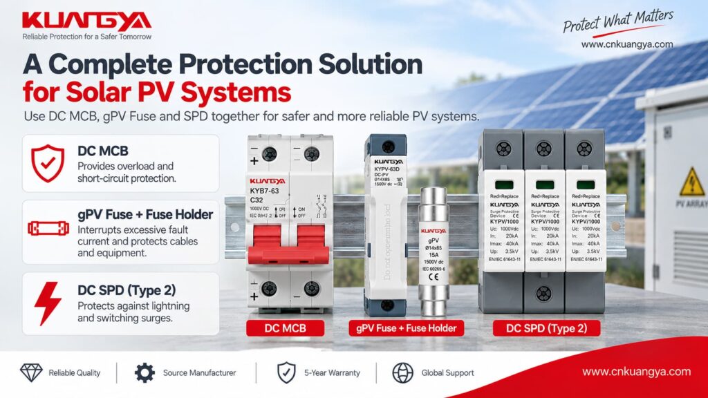
Imax represents a surge-discharge current characteristic.
Fuse current rating relates to overcurrent protection.
A 40 kA Imax rating does not mean a 40 A backup fuse is required.
So, does an SPD need a backup fuse or circuit breaker?
Sometimes yes—but not always as a separate device.
正しい SPD backup fuse selection starts with the manufacturer’s technical data rather than a universal ampere rating.
The correct decision depends on the relationship between:
SPD → F1 → F2 → available fault current → conductors → electrical system
Before installing additional backup protection, first check whether the existing upstream device already satisfies the SPD manufacturer’s requirements.
If dedicated protection is required, verify:
Most importantly:
Never select an SPD backup fuse only from Type 1 / Type 2, In or Imax. Use the exact manufacturer’s backup-protection requirements and the actual system conditions.
For photovoltaic applications, you can also review KUANGYA’s DC surge protective devices for solar PV systems when comparing Type 2 and Type 1+2 DC SPD options.

