温州市岳陽工業区 325000
勤務時間
月曜日~金曜日:午前7時~午後7時
週末午前10時~午後5時
温州市岳陽工業区 325000
勤務時間
月曜日~金曜日:午前7時~午後7時
週末午前10時~午後5時

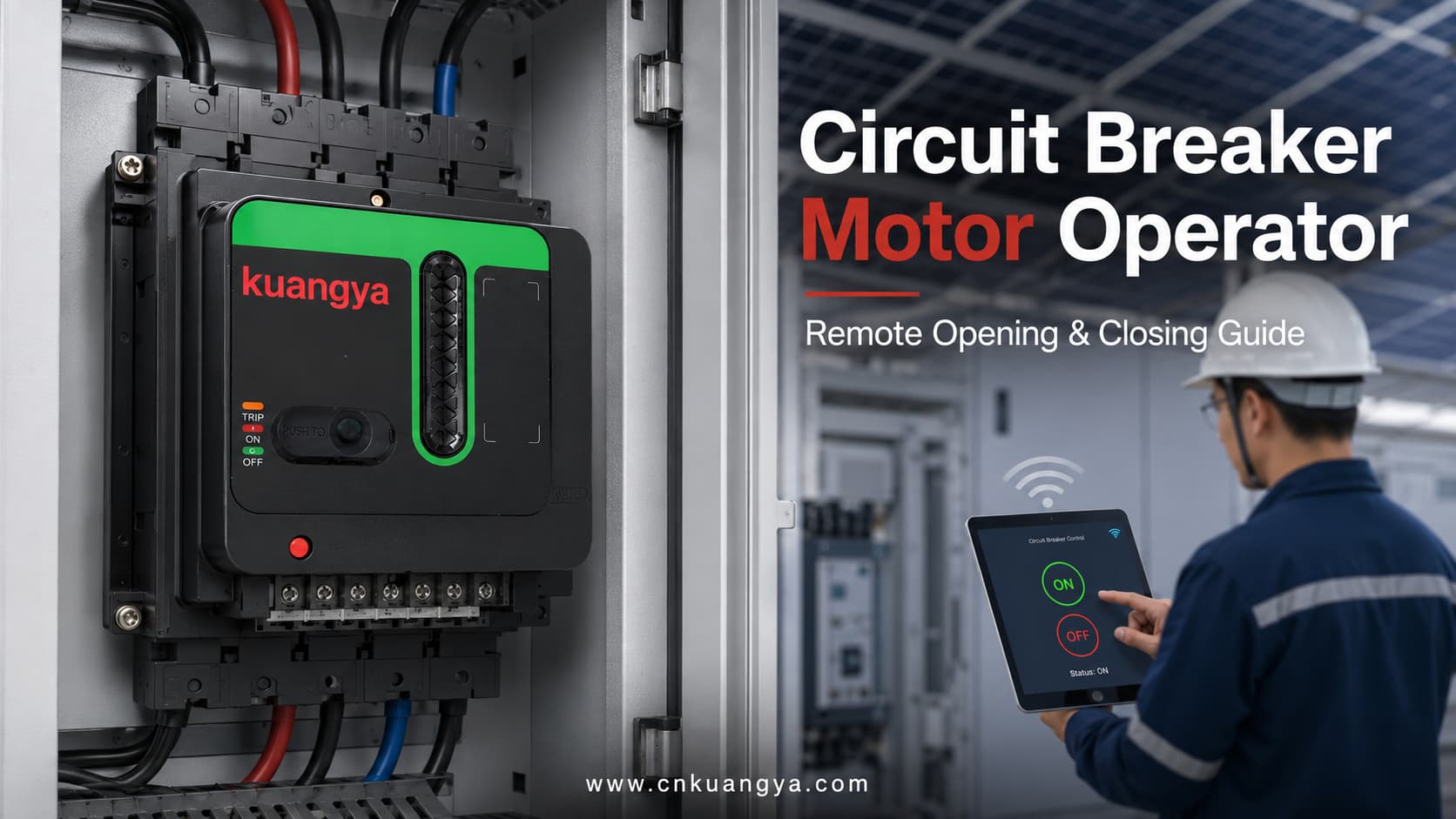
A 配線用遮断器用電動操作機構 互換性のある配線用遮断器を機械的に操作するための電動アクセサリです。.
電気指令を受信すると、電動操作装置が遮断器の機構を駆動し、遠隔での開閉操作を行います。配線用遮断器、電動操作装置、および制御構成に応じて、リセット、現地手動操作、状態表示、インテリジェント制御システムとの統合にも対応可能です。.
電動操作装置は、配線用遮断器の電気的保護機能を代替するものではありません。遮断器は引き続き過負荷保護、短絡保護、その他の適用される保護機能を提供し、電動操作装置は遠隔操作の手段を提供します。.
主要な遮断器メーカーの電動操作機構は、一般的に遠隔開閉、配電自動化、常用・予備電源切替、および負荷管理アプリケーションに使用されます。.
| 項目 | 説明 |
|---|---|
| 主な製品名 | 配線用遮断器用電動操作装置 |
| その他の一般的な名称 | 回路遮断器用電動操作機、MCCB用電動操作装置、電動操作機構 |
| 主な目的 | 電気信号により適合する遮断器を操作すること |
| 主な動作 | 遠隔開閉操作 |
| 追加機能 | リセット、現地操作および状態表示(構成による) |
| 設置方法 | 互換性のある遮断器の前面、側面、または取付構造への取り付け |
| 共通制御電源 | 押しボタン、リレー、PLC、SCADA、ATSコントローラ、または監視システム |
| 代表的な用途 | 太陽光発電(PV)配電盤、産業用パネル、切替システム、および無人サイト |
| 主回路保護 | 配線用遮断器により提供 |
| 制御電源 | 通常、個別のACまたはDC補助電源が必要 |
| 互換性 | 遮断器のモデル、サイズ、およびハンドル動作と照合して確認する必要がある |
| 手動操作 | 多くの設計で利用可能だが、方法は製品によって異なる |
従来の遮断器は通常、手動で操作される。技術者は配電盤の前に立ち、遮断器のハンドルをON、OFF、またはリセット位置に動かす必要がある。.
このアプローチは、アクセスが容易で切り替え頻度が低い小型配電盤には実用的です。しかし、電気設備が広大な工場内に分散している場合や、遠隔地の無人サイトに設置されている場合、手動操作は効率が低下します。.
例を挙げよう:
これらのプロジェクトでは、単純な開閉操作であっても、担当者が盤の場所を特定し、現場へ移動し、アクセス許可を取得した上で、手動でブレーカーを操作する必要があります。.
電動操作機構により、対応するブレーカーはリモートコントロールパネルや自動化システムからの電気指令を受けることが可能になります。これにより、特定の開閉操作を集約し、繰り返される手動介入を削減できます。.
| 比較項目 | 配線用遮断器の手動操作 | 配線用遮断器の電動操作 |
|---|---|---|
| 設置場所 | ブレーカーの正面 | 現地または遠隔操作ポイントから |
| 必要な人員 | 技術者は盤内へアクセスする必要がある | 一部の操作は遠隔で完了可能 |
| 制御方式 | 機械式ハンドル操作 | 電気指令および機械的操作 |
| PLC統合 | 通常、アクセサリなしでは利用不可 | 適切な制御配線により可能 |
| 集中制御 | 限定 | 集中電気制御に適している |
| 位置フィードバック | 目視検査 | 電気的フィードバックの追加が可能 |
| 適切なプロジェクト | 小型でアクセスが容易なシステム | 大規模、遠隔、または自動化された設備 |
| 手動バックアップ | スタンダード | メカニズムの設計により保持されることが多い |
| 設置の複雑さ | より低い | 機械的な適合と制御配線が必要 |
| 初期コスト | より低い | 高くなるが、現場での繰り返しの介入を減らせる可能性がある |
遠隔操作を行っても、有資格者、電気的インターロック、または安全な保守手順の必要性がなくなるわけではありません。これは単に、遮断器が操作指令を受け取り実行する方法を変更するだけです。.
電動操作機構(モーターオペレーターとも呼ばれる)は、 配線用遮断器用電動操作装置, であり、対応する遮断器に取り付けられるか、または接続されます。.
その目的は、電気的な制御指令を制御された機械的動作に変換することです。.
配線用遮断器(MCCB)で一般的に使用される外部電動操作装置の場合、内部のモーターがギア、カム、またはリンク機構を駆動します。この機構が遮断器のハンドルを、サポートされている各操作位置の間で動かします。.
詳細な構造は、遮断器の種類やメーカーによって異なります。一部の外部機構は遮断器のハンドルを直接操作しますが、大型の気中遮断器(ACB)用の電動操作装置は、投入バネの電気的なチャージなどの機能を実行する場合があります。このため、実際の遮断器システムに合わせて、動作原理と付属品の構成を常に確認する必要があります。.
| コンポーネント | 主な機能 |
|---|---|
| 電動機 | 機構を動作させるために必要な力を生成する |
| 歯車伝動装置 | モーターの回転を制御された動きに変換する |
| カムまたはリンク機構 | 動きをブレーカーハンドルに伝達する |
| 取付構造 | 操作装置を正しい位置に固定する |
| 制御端子 | 電源および開閉指令の受信 |
| リミットスイッチ | 目標位置に到達した際にモーターを停止させる |
| 位置表示器 | 機構の動作状態を表示する |
| 手動操作装置 | 必要に応じて現地操作を可能にする |
| 現地/遠隔切替スイッチ | 操作指令の許可ソースを切り替える |
| 補助接点 | Provide ON, OFF or TRIP feedback when included |
| Protective cover | Reduces accidental contact with moving parts |
| Interlocking interface | Helps coordinate operation with other breakers or controllers |
Not every motor operator contains all the components listed above. The actual structure depends on the product design and required functions.
A typical motorized operating sequence consists of five stages.
The operating command may come from:
The command normally instructs the mechanism to open or close the breaker.
After the command is received, the internal motor is powered by the auxiliary control supply.
The control voltage must match the rated voltage of the motor operator. The main-circuit voltage of the breaker and the auxiliary control voltage of the operator are separate specifications.
The motor drives the internal gears, cam or linkage.
This converts the motor’s rotational movement into the mechanical movement required to operate the breaker handle.
The operating mechanism moves the breaker toward the required ON or OFF position.
When the target position is reached, a limit switch or internal position-control component stops the motor. This prevents the motor from continuing to apply force after the operation is complete.
When suitable auxiliary contacts are installed, the breaker or motor operator can send a feedback signal to the control system.
Communicating breaker systems can receive opening, closing and reset commands and transmit states such as OFF, ON and tripped status. The available feedback functions depend on the breaker and control module.
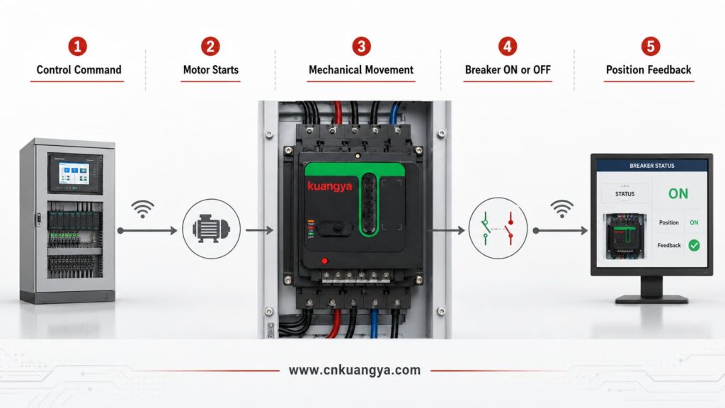
| ステップ | Control-System Action | Motor-Operator Action | Breaker Condition |
|---|---|---|---|
| 1 | Sends an opening or closing command | Receives the control signal | Remains in its previous position |
| 2 | Supplies the required control voltage | Internal motor starts | Begins changing position |
| 3 | Maintains the required operating signal | Gear and linkage transfer movement | Handle moves toward the target position |
| 4 | Monitors the operating process | Limit control stops the motor | Reaches ON or OFF |
| 5 | Receives an auxiliary-contact signal | Returns or supports position indication | Final position is confirmed |
| 6 | Records the result if connected to a monitoring system | Returns to standby condition | Ready for the next permitted operation |
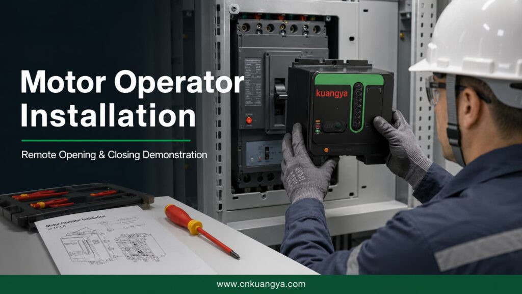
The following video demonstrates the complete installation of a universal motor operator designed for compatible circuit breakers.
It shows how the operating mechanism is positioned and connected to the circuit breaker, followed by a demonstration of remote opening and closing.
This type of motor operator can be used in photovoltaic power distribution cabinets, industrial control panels and intelligent electrical control projects.
| Demonstration Stage | What the Viewer Can See |
|---|---|
| Product preparation | The motor operator and circuit breaker before installation |
| Mounting-position confirmation | The operator is aligned with the circuit breaker |
| Mechanical installation | The motor operator is secured in the required position |
| Handle connection | The operating linkage is connected to the breaker handle |
| Installation adjustment | The mechanism is checked for correct travel and alignment |
| Remote opening | The motor operator moves the breaker from ON to OFF |
| Remote closing | The motor operator moves the breaker from OFF to ON |
| Operation confirmation | The breaker completes the required mechanical movement |
| Final inspection | The installed mechanism is checked for stable operation |
Correct alignment is essential. If the mechanism is installed in the wrong position, the breaker may not complete its full opening, closing or reset movement.
The exact functions of a motor operator for a circuit breaker depend on the breaker model, operating mechanism, wiring arrangement and control system.
The motor operator can move a compatible breaker from its closed position to its open position after receiving an opening command.
Remote opening is useful when a circuit must be isolated from a control room, central panel or monitoring station.
The motor operator can close a compatible breaker after receiving a closing command and after the required system conditions have been satisfied.
Remote closing should be controlled by suitable logic and interlocking. A closing command should not be issued simply because the breaker is open.
After certain trip events, the breaker mechanism must be moved through a reset sequence before it can be closed again.
Some motor operators support resetting, but the method varies considerably. Resetting may be manual, remote or automatic depending on the breaker and control arrangement.
Schneider Electric’s documentation, for example, distinguishes between local reset, remote reset and configurations in which resetting after an electrical-fault trip is restricted unless the system has been specifically configured for it.
Official motor mechanism operating guidance from Schneider Electric shows that a communicating motor mechanism can receive opening, closing and reset commands while transmitting ON, OFF and trip-status information.
Many motor operators retain a local manual operating function.
This may be required during:
The manual operating procedure must follow the instructions for the actual mechanism.
Some mechanisms include a selector that determines whether operation is controlled locally or remotely.
This can help prevent unintended remote commands during maintenance or commissioning.
Position feedback allows a control or monitoring system to determine whether the breaker is:
The available signals depend on the auxiliary contacts and communication modules used in the system.
| 機能 | 説明 | Typical Availability |
|---|---|---|
| Remote opening | Opens the breaker after an electrical command | 共通 |
| Remote closing | Closes the breaker after an electrical command | 共通 |
| Remote reset | Resets a tripped breaker remotely | Model- and configuration-dependent |
| Automatic reset | Resets after a permitted event according to control logic | Model- and system-dependent |
| 手動操作 | Allows the mechanism to be operated locally | Common on many designs |
| Local/remote selection | Selects the source of operating commands | Model-dependent |
| ON indication | Reports or displays the closed position | Requires appropriate indication |
| OFF indication | Reports or displays the open position | Requires appropriate indication |
| TRIP indication | Reports that the breaker has tripped | Requires trip-status contact |
| PLC統合 | Accepts commands from an automation controller | Requires compatible control circuit |
| SCADA integration | Supports remote supervisory control | Requires suitable interface equipment |
| Electrical interlocking | Prevents conflicting operating commands | Requires correct system design |
The presence of a motor operator does not automatically mean that every function in this table is available. The actual functions must be confirmed from the product datasheet and wiring diagram.
Motor operators are often confused with other circuit-breaker accessories.
Although these devices can all be connected to a control circuit, they have different purposes.
| Accessory | 主な目的 | Remote Opening | Remote Closing | リセット機能 | Status Feedback |
|---|---|---|---|---|---|
| Motor operator | Mechanically operates the circuit breaker | はい | はい | Depending on model | Possible |
| シャントトリップ | Trips or opens the breaker after receiving a voltage signal | はい | いいえ | いいえ | いいえ |
| Undervoltage release | Opens or prevents closing when its supply voltage is too low | Yes, under specified conditions | いいえ | いいえ | いいえ |
| Closing release | Initiates closing on supported breaker systems | いいえ | はい | いいえ | いいえ |
| Auxiliary contact | Indicates whether the breaker is open or closed | いいえ | いいえ | いいえ | はい |
| Alarm contact | Indicates that a protective trip has occurred | いいえ | いいえ | いいえ | はい |
| Trip-indication contact | Reports a trip caused by a specified condition | いいえ | いいえ | いいえ | はい |
A shunt trip is designed to open a circuit breaker when its coil receives the specified voltage. It does not normally close or mechanically reset the breaker.
アン undervoltage release responds when its control voltage falls below the required operating range. Depending on the product, it can open the breaker or prevent it from closing.
アン auxiliary switch provides remote electrical indication of whether the breaker is open or closed. It reports status but does not operate the breaker.
Eaton documentation similarly distinguishes a motor operator, which supports electrical operation, from a shunt trip that opens the breaker and an auxiliary switch that provides remote position indication.
| Project Requirement | More Relevant Accessory |
|---|---|
| Remotely open the breaker only | Shunt trip may be sufficient |
| Remotely open and close the breaker | Motor operator or breaker-specific electrical operating system |
| Prevent closing when control voltage is lost | Undervoltage release |
| Report ON and OFF positions | Auxiliary contact |
| Report an electrical-fault trip | Alarm or trip-indication contact |
| Reset and reclose a supported breaker remotely | Compatible motor operator plus appropriate control logic |
| Transfer between two power sources | Motor operators, controllers and interlocking may be required |
| Integrate the breaker into PLC control | Motor operator plus status and control interfaces |
A motorized operating mechanism can be used wherever a compatible circuit breaker needs to be operated remotely or integrated into an automated electrical-control system.
| 申し込み | Why the Motor Operator Is Used | Typical Control Source |
|---|---|---|
| Photovoltaic distribution cabinet | Supports remote switching and centralized PV-system control | PLC or solar monitoring system |
| Industrial control panel | Reduces repeated manual operation across multiple cabinets | PLC or control relay |
| Automatic transfer system | Coordinates switching between normal and backup sources | ATS controller |
| Generator distribution system | Controls selected breakers during generator operation | Generator controller |
| Energy storage system | Supports remote isolation and auxiliary-circuit control | EMS or PLC |
| Telecommunications site | Allows operation at remote or unattended facilities | Remote monitoring system |
| Intelligent building | Integrates breaker operation into centralized building control | BMS(バッテリーマネジメントシステム) |
| Water treatment facility | Supports automated control of distributed electrical equipment | PLC or SCADA |
| Mining or remote infrastructure | Reduces the need for personnel to access distant cabinets | Remote control panel |
| Agricultural power system | Supports centralized operation across distributed equipment | PLC or relay control |
| Data center auxiliary distribution | Supports coordinated switching of selected non-critical circuits | Power-management system |
| Manufacturing production line | Allows circuit operation as part of an automated sequence | PLC |
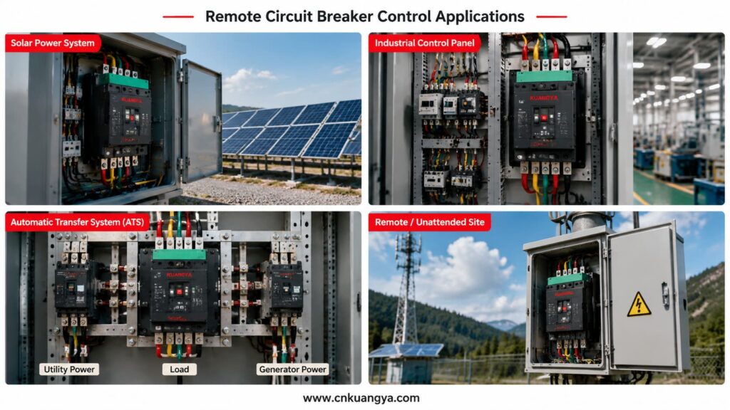
Photovoltaic installations can contain inverters, distribution cabinets, monitoring equipment and auxiliary electrical systems across large areas.
When a breaker must be operated manually, technicians may need to travel to the cabinet even when the required action is relatively simple.
Remote breaker operation should be considered as one part of a coordinated solar PV electrical protection system, together with overcurrent protection, surge protection, electrical isolation and power distribution equipment.
A compatible motor operator can allow selected opening or closing commands to be issued from a monitoring station or control system.
Possible applications include:
For projects that integrate circuit breakers, fuses, SPDs and isolation devices inside one enclosure, explore our 太陽光発電用接続箱ソリューション for residential, commercial and remote solar installations.
However, remote operation must not be confused with unrestricted automatic reclosing.
If a breaker has tripped because of a short circuit, overload, insulation failure or equipment damage, the cause should be identified before the circuit is energized again.
Circuit-breaker manufacturers specifically warn against reclosing after an electrical fault without first inspecting and repairing the downstream equipment when necessary.
Factories often contain numerous electrical panels serving production lines, pumps, ventilation systems, conveyors and other equipment.
A circuit breaker motor operator can allow selected circuits to be controlled from:
The motor operator can form part of a larger sequence. For example, the system may open a breaker before equipment maintenance or close a breaker only after other safety conditions have been confirmed.
Remote operation should be coordinated with:
Automatic transfer systems switch a load between two power sources, such as:
Motor-operated breakers may be used as the switching devices in these systems.
A suitable controller sends opening and closing commands according to source availability and system conditions.
The system must normally include interlocking to prevent two incompatible sources from being connected at the same time.
| Sequence | Source A Breaker | Source B Breaker | Controller Action |
|---|---|---|---|
| 1 | Closed | Open | Monitors Source A |
| 2 | Opens after Source A failure | Remains open | Confirms Source A breaker is open |
| 3 | Open | Closes | Transfers load to Source B |
| 4 | Remains open | Closed | Monitors source recovery |
| 5 | Open | Opens | Prepares transfer back |
| 6 | Closes | Open | Restores supply from Source A |
Motor-operated breakers are also commonly used in automatic transfer switch solutions to coordinate switching between normal, standby and generator power sources.
This is only a simplified example. An actual transfer system requires project-specific timing, protection, interlocking and control logic.
The term universal motor operator is often used for an adjustable mechanism designed to work with several compatible breaker dimensions or frame sizes.
However, “universal” should not be interpreted as “suitable for every circuit breaker.”
Circuit breakers from different manufacturers and product series can have different:
A universal design may provide adjustable mounting positions, but compatibility still needs to be checked.
A safer technical description is:
A universal motor operator designed for a range of compatible circuit breakers.
| Compatibility Factor | Why It Must Be Confirmed |
|---|---|
| Breaker brand | Different manufacturers use different mechanical designs |
| Complete breaker model | Identifies the specific series and construction |
| Frame size | Affects breaker dimensions and operating force |
| Handle position | Must align with the operator mechanism |
| Handle dimensions | Must fit the operating interface correctly |
| Handle travel | The operator must complete the full ON and OFF movement |
| Reset movement | The mechanism must support the required trip-reset sequence |
| Mounting holes | Determine whether the operator can be securely installed |
| Breaker depth | Affects the installation and alignment position |
| ポール数 | May affect overall breaker construction |
| Front accessories | Covers or rotary handles may interfere with installation |
| Required torque | The operator must provide sufficient operating force |
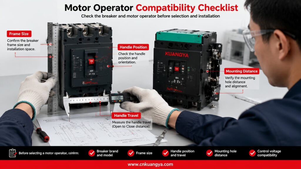
The supplier should receive clear photographs and dimensional information before confirming that a universal motor operator is suitable.
Selecting the correct motorized operating mechanism requires more than knowing the breaker’s rated current.
A 250 A or 400 A description alone is normally insufficient because breakers with the same rated current can have different frame sizes, dimensions and operating mechanisms.
The complete breaker model is one of the most important pieces of information.
Provide:
A nameplate photograph is highly recommended.
The frame size influences:
The breaker’s rated current and frame size are related but are not always identical.
Before selecting the operating mechanism, engineers must first confirm the breaker voltage, rated current, frame size, breaking capacity and accessory requirements. Read our DC MCCB selection guide for a more detailed explanation.
The motor operator normally requires a separate auxiliary power supply.
The buyer must specify:
Writing only “220 V” is incomplete. It should be written as 220 VAC または 220 VDC.
The buyer should state whether the project requires:
The supplier needs to know whether commands will come from:
Remote systems should not rely only on sending commands.
Feedback may be required for:
Provide information about:
| 選定項目 | Information Required from Buyer | なぜ重要なのか |
|---|---|---|
| Breaker brand | Manufacturer name | Identifies the basic mechanical design |
| Complete model | Full breaker model number | Confirms the exact breaker series |
| Frame size | Breaker frame specification | Determines dimensions and operating force |
| 定格電流 | Breaker current rating | Helps confirm the breaker configuration |
| ポール数 | 2P, 3P or 4P | Helps identify the physical version |
| Front photograph | Clear image of the breaker handle and cover | Supports mechanical compatibility checking |
| Side photograph | Clear side view | Helps check depth and mounting arrangement |
| Nameplate photograph | Full readable nameplate | Confirms electrical and model information |
| Control voltage | Voltage value plus AC or DC | Must match the auxiliary power supply |
| Required functions | Opening, closing, reset and manual operation | Determines the mechanism configuration |
| Control source | Button, relay, PLC, SCADA or ATS | Determines wiring and signal requirements |
| Feedback requirement | ON, OFF or TRIP signals | Determines auxiliary contact requirements |
| 申し込み | PV, industrial, ATS or other use | Helps evaluate the operating requirements |
| 数量 | Number of units | Required for quotation and production planning |
| Certification requirement | Required market or project documentation | Determines applicable product and document needs |
The circuit breaker used with a motorized operating mechanism should comply with the applicable low-voltage circuit breaker standards. IEC 60947-2 specifies requirements for industrial and similar low-voltage circuit breakers. The compatibility, control voltage and installation requirements of the motor operator must also be confirmed separately.
Different motor-operator models may be manufactured for different AC or DC control supplies.
The following table provides general examples only. It is not a fixed KUANGYA product-voltage list.
| Example Control Supply | 現在のタイプ | Common Control Environment |
|---|---|---|
| 24 VDC | Direct current | PLC and automation systems |
| 48 VDC | Direct current | Telecommunications and industrial control |
| 110 VDC | Direct current | Utility and substation control systems |
| 220 VDC | Direct current | Specialized industrial control systems |
| 110 VAC | Alternating current | Industrial distribution equipment |
| 220 VAC | Alternating current | General control panels |
| 230 VAC | Alternating current | International low-voltage systems |
The available operating range, inrush current, power consumption and command duration must be confirmed from the datasheet for the selected model.
Installation should be carried out by qualified personnel according to the product wiring diagram, breaker instructions and local electrical requirements.
Installers can also refer to this official motor operator installation instruction for an example of mechanical mounting, control wiring and remote opening, closing and resetting procedures.
Before installation:
After installation:
Motor-mechanism wiring should not be changed casually. Manufacturer documentation warns that incorrect modifications can create repeated closing on an electrical fault and requires the mechanism to be wired according to its specified diagram.
| 点検項目 | Before Installation | After Installation |
|---|---|---|
| Breaker compatibility confirmed | ✓ | - |
| Breaker model recorded | ✓ | - |
| Control voltage verified | ✓ | - |
| Main circuit isolated | ✓ | - |
| Control circuit isolated | ✓ | - |
| Wiring diagram reviewed | ✓ | - |
| Mounting position aligned | ✓ | ✓ |
| Mechanical linkage secured | - | ✓ |
| Full opening movement completed | - | ✓ |
| Full closing movement completed | - | ✓ |
| Reset sequence tested when applicable | - | ✓ |
| Manual operation tested | - | ✓ |
| Remote opening tested | - | ✓ |
| Remote closing tested | - | ✓ |
| Position feedback tested | - | ✓ |
| Interlocking tested | - | ✓ |
| Abnormal noise checked | - | ✓ |
| Mechanical resistance checked | - | ✓ |
Some breaker and motor-operator configurations can support reset and remote reclosing.
However, the fact that a breaker can be closed remotely does not mean that immediate reclosing is safe.
A circuit breaker may trip because of:
Before resetting and closing the breaker, the system or responsible personnel should determine whether the fault has been cleared.
For critical applications, the control logic may include:
After an electrical-fault trip, some manufacturer configurations require local reset by default, while remote reset must be specifically enabled through the relevant communication and control system.
| チェック | Question Before Reclosing |
|---|---|
| Trip cause | Has the reason for the trip been identified? |
| Fault condition | Has the short circuit, overload or equipment fault been cleared? |
| Downstream circuit | Has the connected equipment been inspected when necessary? |
| Breaker condition | Is the breaker mechanically ready to reset and close? |
| Voltage condition | Is the source voltage within the permitted range? |
| Interlocking | Are all interlocking conditions satisfied? |
| 位置フィードバック | Is the breaker’s actual position confirmed? |
| Number of attempts | Has the system exceeded the permitted reclosing attempts? |
| Personnel safety | Are personnel clear of the affected equipment? |
| Authorization | Has the required automatic or manual permission been received? |
Troubleshooting should begin only after the main and control circuits have been made safe.
The following table lists possible causes. It does not replace the actual product manual or electrical testing.
| 問題 | 考えられる原因 | 推奨チェック |
|---|---|---|
| Motor does not operate | No auxiliary power | Measure and confirm the control supply |
| Motor does not operate | Incorrect terminal wiring | Compare the wiring with the product diagram |
| Breaker does not fully close | Operator is not correctly aligned | Check the mounting and handle position |
| Breaker does not fully open | Linkage is blocked | Inspect the mechanical transmission |
| Motor continues running | Limit-switch or position-control problem | Stop operation and inspect the control mechanism |
| Breaker stops between positions | Insufficient travel or mechanical resistance | Check adjustment and breaker compatibility |
| Remote operation is intermittent | Loose terminal or unstable signal | Inspect terminals, relay output and control voltage |
| Position feedback is incorrect | Auxiliary contact wired incorrectly | Verify the contact type and wiring |
| Manual operation is difficult | Mechanical interference | Isolate power and inspect the installation |
| Reset cannot be completed | Reset travel is insufficient | Check the required breaker reset movement |
| Breaker trips again after closing | Electrical fault remains | Stop reclosing and inspect the downstream circuit |
| Operator makes abnormal noise | Gear or linkage is obstructed | Stop operation and inspect the mechanism |
| PLC sends a command but nothing happens | Signal type is incompatible | Confirm pulse, maintained contact and interface requirements |
| Opening works but closing does not | Closing permission or interlocking is absent | Check ready-to-close and interlocking conditions |
そうだ。.
The circuit breaker provides electrical protection and circuit switching. The motor operator is an accessory that operates a compatible breaker through electrical commands.
Yes, compatible motor mechanisms can provide remote opening and closing. The exact operation depends on the breaker, motor operator, control voltage and wiring configuration.
そうだ。.
A universal motor operator may be adjustable for several compatible breaker sizes, but the breaker model, handle position, travel distance, mounting dimensions and required operating force must still be checked.
Some models and configurations support reset operation.
The reset may be manual, remote or automatic. Resetting after an electrical-fault trip may be restricted by the breaker system and control configuration.
そうだ。.
The overload and short-circuit protection functions are provided by the circuit breaker and its trip unit.
そうだ。.
A shunt trip is primarily used to open the breaker after receiving an electrical signal. A motor operator may mechanically open and close a compatible breaker.
Many motor operators retain a manual operating method, but the exact procedure depends on the product design.
Yes, when the control voltage, signal type, wiring and interface are compatible with the PLC system.
A relay interface may be required depending on the PLC output and motor-operator control circuit.
そうだ。.
The cause of a protective trip should be identified before the circuit is energized again. Repeated closing on an unresolved fault can cause equipment damage and create safety risks.
Send the breaker brand, complete model, frame size, pole number, control voltage, required functions, quantity and clear photographs.
Customers can copy the following format when requesting a quotation:
Product required:
Motorized operating mechanism for circuit breaker

Circuit breaker brand:

Complete circuit breaker model:

Breaker frame size:

Rated current:

Number of poles:

Control voltage:
Please specify AC or DC.

Required functions:
Remote opening / remote closing / reset / manual operation

Control method:
Push button / relay / PLC / SCADA / ATS / other

Position feedback required:
ON / OFF / TRIP / other

Application:
PV distribution cabinet / industrial panel / ATS / other

Installation environment:

Quantity:

Required certificates or documents:

Please provide:
Product datasheet
Wiring diagram
Installation dimensions
Compatibility confirmation
Quotation
Delivery time
Attach the following materials whenever possible:
A 配線用遮断器用電動操作機構 converts an electrical command into mechanical breaker operation.
It can enable remote opening, remote closing, local manual operation, centralized control and integration with PLC, SCADA, ATS or intelligent monitoring systems.
Motor operators are particularly useful in:
However, correct selection is essential.
A product described as a universal motor operator is not automatically compatible with every circuit breaker. The breaker model, frame size, handle dimensions, operating travel, control voltage and required functions must all be checked before ordering.
Remote reset and reclosing must also be controlled carefully. A circuit breaker that has tripped because of an electrical fault should not be closed again until the fault condition has been evaluated and cleared.
KUANGYA provides motorized operating mechanisms for circuit breaker control applications, including photovoltaic distribution cabinets and intelligent electrical-control projects.
Send us your circuit breaker model, nameplate photograph, control voltage, required functions and quantity for product matching, technical information and quotation.
Contact KUANGYA for inquiries, model selection and bulk-order quotations.

