温州市岳陽工業区 325000
勤務時間
月曜日~金曜日:午前7時~午後7時
週末午前10時~午後5時
温州市岳陽工業区 325000
勤務時間
月曜日~金曜日:午前7時~午後7時
週末午前10時~午後5時

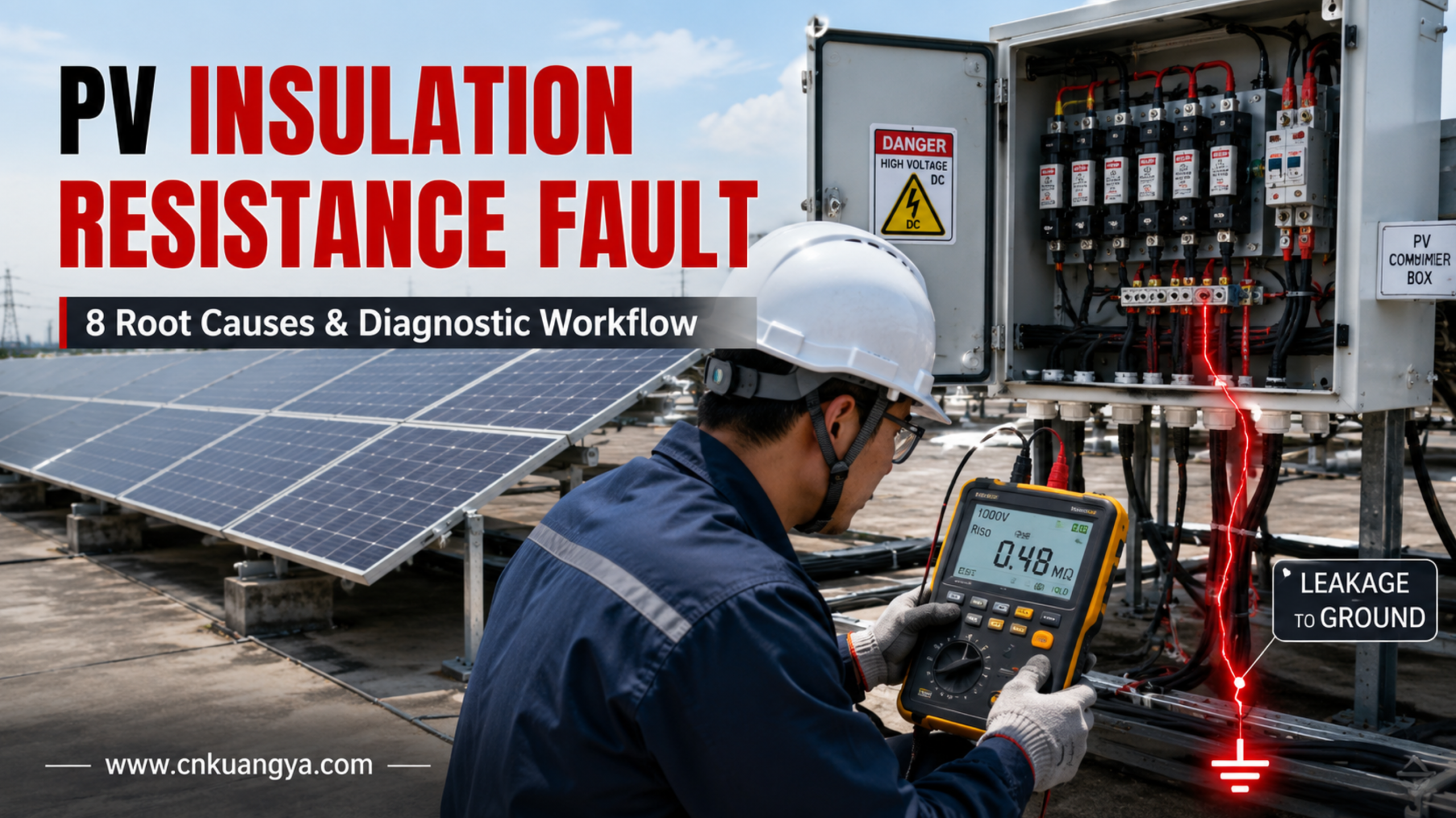
A PV絶縁抵抗故障 は、太陽光発電の運用および保守において最も厄介な問題の一つです。.
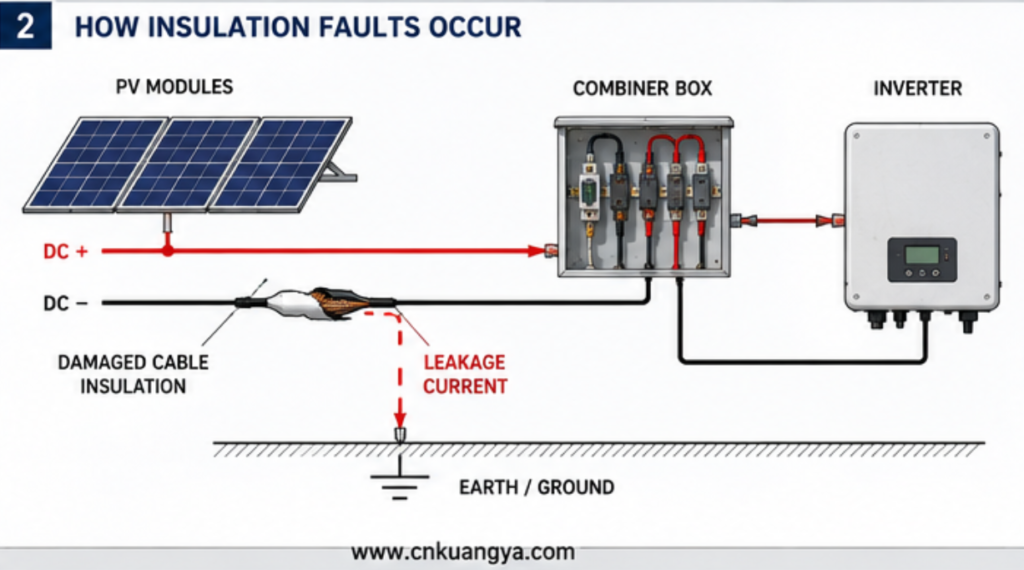
朝、インバータが起動しないことがあります。乾燥した時間が数時間続くと警告が消え、雨が降ると再び表示される場合があります。開放電圧を測定した際には1つのストリングが正常に見えても、PVアレイ全体では依然として絶縁抵抗値の低下が報告されることがあります。.
これらの故障は、必ずしも直接的な短絡が原因ではないため、診断が困難です。.
太陽光発電アレイは、湿気、絶縁被覆の損傷、コネクタの汚染、モジュール部品の劣化、またはDC機器の欠陥によって、DC活線回路と大地との間に不要な導電経路が形成されていても、一見正常な電圧を生成し続けることがあります。.
その結果、以下の事象が発生する可能性があります:
本ガイドでは、太陽光発電システムの絶縁故障が発生する仕組み、故障が間欠的に現れる理由、および技術者が部品を無作為に交換するのではなく、体系的な診断プロセスを用いる方法について解説します。.
PVアレイの設計においては、DC配線、電気的保護、接地、絶縁監視、および地絡検出の要件を考慮する必要があります。これらの安全原則は以下で扱われています。 太陽光発電アレイ設計に関するIEC 62548-1. 現行のIEC 62548-1の枠組みは、PVアレイのDC配線、電気的保護、開閉装置、および接地規定を網羅しています。一方、IEC 62446-1は文書化、試運転試験、および検査を扱い、IEC 62446-2は系統連系型PVシステムの保守およびトラブルシューティングを扱っています。.
最も一般的な原因は以下の通りである:
トラブルシューティングにおける最も重要なルールは以下の通りです:
DCアレイを体系的に切り離してテストするまでは、PV絶縁故障をインバーターの問題として扱わないでください。.
インバーターは、単にPVフィールドの上流のどこかで発生している問題を検知している可能性があります。.
健全なPVアレイでは、正極および負極のDC導体は、システム設計に従い、接触可能な導電部および接地から適切に絶縁されている必要があります。.
直流活線回路と他の導電経路または接地基準との間に意図しない導電路が形成されると、絶縁不良が発生します。.
この経路は、以下のような要因によって形成される可能性があります。
故障は必ずしも完全な金属短絡として始まるとは限らない。.
比較的弱い漏電経路として始まる場合がある。.
そのため、PVシステムは以下のような挙動を示すことがある:
この断続的な挙動は、絶縁不良の特定に多くのメンテナンス時間を要する理由の一つです。.
最新の電力変換装置は、動作前または動作中にPV直流回路と大地間の電気的関係を監視する場合がある。.
検出された絶縁状態がインバータメーカーの許容範囲外となった場合、インバータは以下の動作を行う可能性がある。
正確なアラーム名称はメーカーによって異なる。.
現場で一般的に見られる記述の例は以下の通りです:
重要な点は、アラームが何を特定しているかということです 状態, 、必ずしも故障したコンポーネントとは限らない。.
したがって、アレイのテストを行わずにインバータを交換しても、問題が解決しない可能性がある。.
太陽光発電設備の規格では、アレイの設計、PV機器の設置、および試験・保守活動が区別されている。そのため、適切な診断を行うには、電力変換機器だけでなく、DCシステム全体を調査する必要がある。.
したがって、絶縁アラームは、単なるインバータの問題として扱うのではなく、より広範なDC保護アーキテクチャの一部として調査されるべきである。インバータ周辺のサージ、過電流、アーク故障、接地、および絶縁リスクに関するより広範な検討については、当社のガイドを参照のこと。 太陽光発電用インバータの保護.
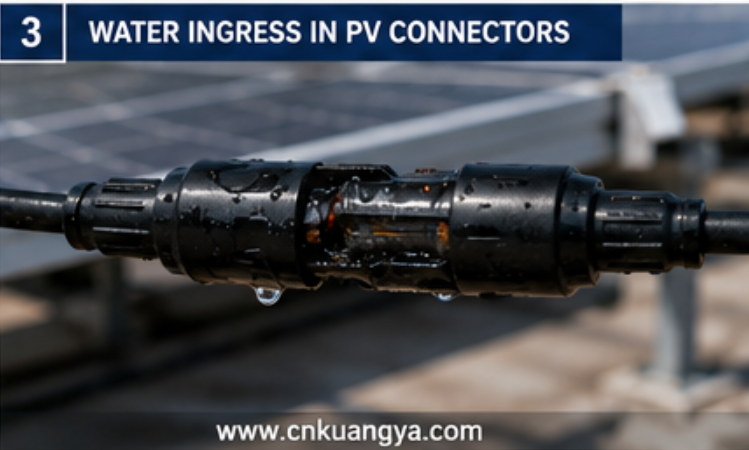
絶縁アラームが天候と強く関連している場合、技術者が最初に調査すべき条件の一つが浸水である。.
コネクタは機械的に接続されているように見えても、導電面に湿気が侵入する可能性があります。.
考えられる理由は以下の通りです。
この不具合は再現が困難な場合があります。.
乾燥した天候の間は、漏電経路が弱まり、インバータが起動する可能性がある。.
雨や結露の後、導電性が高まり、アラームが再発する。.
システム:
このパターンは、湿気に敏感なコンポーネントへ直ちに注意を向けるべきであることを示唆している。.
ただし、最初に見つかった湿ったコネクタが唯一の問題であると技術者が決めつけてはならない。.
大規模なアレイには、複数の劣化箇所が含まれている可能性がある。.
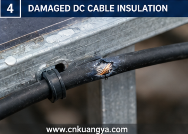
PVケーブルは、長期にわたる環境的および機械的ストレスにさらされている。.
考えられる損傷メカニズムは以下の通りである:
A cable does not need to be completely severed to create an insulation problem.
A small damaged area may expose insulation to:
The resulting leakage path can be intermittent.
Technicians often inspect only visible cable sections.
But cable damage frequently occurs at:
A good inspection therefore follows the actual cable route rather than only the easy-to-see portions.
Not every insulation fault originates in the field wiring.
The PV module itself can become part of the leakage path.
Potential areas include:
Environmental exposure can gradually affect electrical insulation.
The diagnostic challenge is that module output voltage may still appear normal.
A technician may measure acceptable open-circuit voltage and conclude that the module is healthy.
However:
Normal voltage does not prove that insulation to earth is healthy.
These are different electrical conditions.
Module safety requirements are intended to address risks including breakdown of internal or external components that could contribute to electric shock or fire hazards.
Connector problems are frequently discussed only as overheating or arc-fault risks.
However, poor connector installation can also contribute to insulation problems.
Possible issues include:
A connector problem may evolve over time.
The sequence can be:
Mechanical weakness → moisture entry → corrosion or contamination → reduced insulation performance
In another case:
Poor electrical contact → heating → material degradation → carbonized conductive path
This shows why insulation resistance, thermal problems and arc-fault risks should not always be treated as completely separate failure categories.
One defect can develop through several stages.
A surge protective device is installed to manage transient overvoltage.
However, an SPD is also connected electrically between the protected conductors and the relevant protection path.
After repeated electrical stress or internal deterioration, a damaged device may become part of a leakage problem.
Therefore, when troubleshooting an unexplained insulation fault inside a:
the SPD should be included in the diagnostic process.
Do not simply remove an SPD permanently because the insulation alarm disappears.
That only identifies a possible fault source.
The correct action is to:
A failed protection device should not be solved by leaving the system unprotected.
IEC 62548-1 includes the design of DC array wiring and electrical protection devices within PV arrays.
The DC isolator is another component that should not be ignored.
Inside a DC switching device, insulation performance can be affected by:
An isolator may still appear to switch mechanically while its internal electrical condition has deteriorated.Moisture ingress, contaminated insulating surfaces, heat damage, and deteriorated internal contacts can also create broader reliability problems. Our detailed guide to DC Isolator Switch Failure explains how these defects develop and how they should be inspected.
Visible warning signs may include:
However, not every insulation defect is externally visible.
A systematic diagnostic process may require isolating sections of the circuit to determine whether the fault remains upstream or downstream of a particular device.
Many PV insulation faults are created during installation but appear months or years later.Incorrect cable routing, poor terminal preparation, reversed polarity, unsuitable protection devices, and installation errors can also create hidden DC-side defects. See 10 Common DC Protection Wiring Mistakes for a broader review of installation practices that can reduce long-term system reliability.
Consider a cable that is:
On the installation day, the insulation may remain intact.
Later, repeated:
can turn a minor installation defect into an electrical fault.
Projects in different environments may experience different dominant risks.
Possible concerns include:
Possible concerns include:
Possible concerns include:
The same alarm code can therefore have very different physical causes depending on the project environment.
Sometimes technicians search for one dramatically failed component.
But a large array may have no single obvious fault.
Instead, many small leakage paths can combine.
A large installation contains:
Each individual component may contribute only a small leakage path.
Together, however, the total insulation condition seen by the monitoring system can become problematic.
This is especially important when troubleshooting:
The diagnostic method must therefore be capable of dividing the system into smaller sections.
Without sectional isolation, technicians may spend hours looking for one visibly damaged component that does not exist.
This is one of the most useful diagnostic clues.
A solar plant may report:
Low insulation resistance at 6:30 a.m.
Then:
Normal operation at 10:00 a.m.
なぜですか?
One possible explanation is environmental moisture.
Overnight:
After sunrise:
The system appears to “repair itself.”
It has not.
The underlying defect may still exist.
This is why maintenance teams should record:
Fault timing can provide important information before the first electrical test is performed.
These terms are often used incorrectly.
An unwanted conductive path reduces the electrical isolation between the live circuit and earth or other conductive parts.
It may be relatively weak or intermittent.
A live conductor develops an unintended connection toward ground or grounded conductive material.
The severity depends on the electrical system and fault path.
A low-impedance connection occurs between points that should remain at different electrical potentials.
This can produce much higher current.
Current crosses an unintended gap through an electrical arc.
An arc fault may be:
A system can also experience more than one fault mechanism simultaneously.
例えば、こうだ:
Damaged insulation → leakage → carbonization → arc formation
Therefore, accurate diagnosis is more useful than simply assigning one general label such as “electrical fault.”
Random component replacement is one of the least efficient ways to troubleshoot a large PV system.
A better method is progressive isolation.
Before resetting the system, record:
This information may later reveal a pattern.
PV arrays can remain energized when exposed to sufficient light.
Technicians should follow the required site procedures, equipment instructions and applicable electrical safety practices before disconnecting, testing or opening equipment.
IEC 62446-1 addresses commissioning tests and inspection, while IEC 62446-2 provides maintenance-related requirements and recommendations for grid-connected PV systems, including corrective maintenance and troubleshooting.
The key question is:
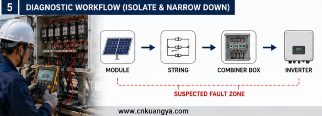
Is the fault in the inverter, main DC circuit, combiner box, string wiring or module section?
Large systems should be progressively divided into smaller electrical sections.
The objective is to determine:
Fault remains → problem is still inside the connected section
または
Fault disappears → investigate the isolated section
This is more efficient than testing every module immediately.
When multiple strings are available, compare the suspected string with healthy strings.
Useful comparisons may include:
The objective is to identify the abnormal branch.
Prioritize locations such as:
Visual inspection should support electrical testing rather than replace it.
Once a problematic string is identified, divide the string or circuit into smaller sections where the system design and safe procedures allow.
This transforms:
“The entire PV plant has an insulation fault.”
into:
“The problem is located within this specific section.”
That is the central principle of efficient fault localization.
After identifying the fault source:
Then verify that the system has returned to an acceptable condition before normal operation.
An intermittent fault creates a dangerous temptation.
The technician resets the inverter.
The system starts.
The service ticket is closed.
Then the alarm returns after the next rain.
Restarting may temporarily restore generation, but it does not answer:
Repeated resets can turn a diagnosable early-stage problem into a more expensive failure.
Avoid:
Connectors should not carry unnecessary cable weight or remain in positions where water and contamination can accumulate.
Combiner boxes and other outdoor enclosures require:
Heavy rain and extreme environmental conditions can reveal developing insulation weaknesses.
Do not wait until an inverter refuses to start.
Periodic inspection and testing can help identify deterioration before it becomes a prolonged production problem.
IEC 62446-2 specifically addresses preventive, corrective and performance-related maintenance of grid-connected PV systems, including maintenance for reliability, safety, fire prevention and troubleshooting.
Experienced troubleshooting teams do not look only at the alarm.
They look at the pattern.
| Fault Pattern | Possible Direction |
|---|---|
| Only after rain | Moisture or ingress |
| Mainly early morning | Condensation-sensitive leakage |
| One specific string | Local string or module fault |
| Entire array | Common DC equipment or distributed leakage |
| After maintenance | Installation or reconnection issue |
| After electrical storm | Inspect affected protective equipment and connected circuits |
| Gradually increasing frequency | Progressive deterioration |
This table is not a substitute for testing.
Its purpose is to help determine where investigation should begin.
It generally means that the electrical isolation between the live PV DC circuit and earth or other conductive parts is lower than the equipment or system expects.
The cause must be identified through inspection and testing.
Moisture may create or strengthen an unintended leakage path in:
The fact that the fault disappears after drying does not mean the system is permanently repaired.
そうだ。.
Possible sources can include the module junction box, external leads or deterioration of the module insulation system.
Normal open-circuit voltage alone does not prove healthy insulation.
A damaged or degraded device connected to the DC protection circuit may need to be considered during diagnosis.
The device should be tested or replaced appropriately rather than permanently removed from the protection system.
Potentially.
Moisture, contamination, heat damage or internal electrical degradation may affect the condition of the device.
Temperature and moisture conditions may change.
Morning condensation or humidity can strengthen a leakage path that becomes less conductive as equipment dries and warms.
Not automatically.
The inverter may simply be detecting an upstream PV array problem.
The DC field should be systematically investigated before the inverter is assumed to be defective.
そうだ。.
They are different electrical fault mechanisms, although deterioration can sometimes allow one fault condition to develop into another.
A PV絶縁抵抗故障 should not be treated as a mysterious inverter error.
It is an electrical condition that requires structured fault localization.
最も一般的な原因は以下の通りである:
The most effective diagnostic strategy is not random replacement.
正しくは次の通りです。
Record → Isolate → Divide → Compare → Inspect → Test → Repair → Verify
This method turns a plant-wide alarm into a manageable electrical problem.
As photovoltaic systems become larger and DC architectures become more complex, insulation integrity remains a fundamental part of safe and reliable PV operation. Current IEC frameworks separately address PV array design, electrical installation, testing, inspection and maintenance, reinforcing the need to treat insulation performance as a system-level engineering issue rather than simply an inverter alarm.

