Zone industrielle WengYang Yueqing Wenzhou 325000
Heures de travail
Du lundi au vendredi : de 7h00 à 19h00
Le week-end : 10H00 - 17H00
Zone industrielle WengYang Yueqing Wenzhou 325000
Heures de travail
Du lundi au vendredi : de 7h00 à 19h00
Le week-end : 10H00 - 17H00
Last Updated: July 4, 2026
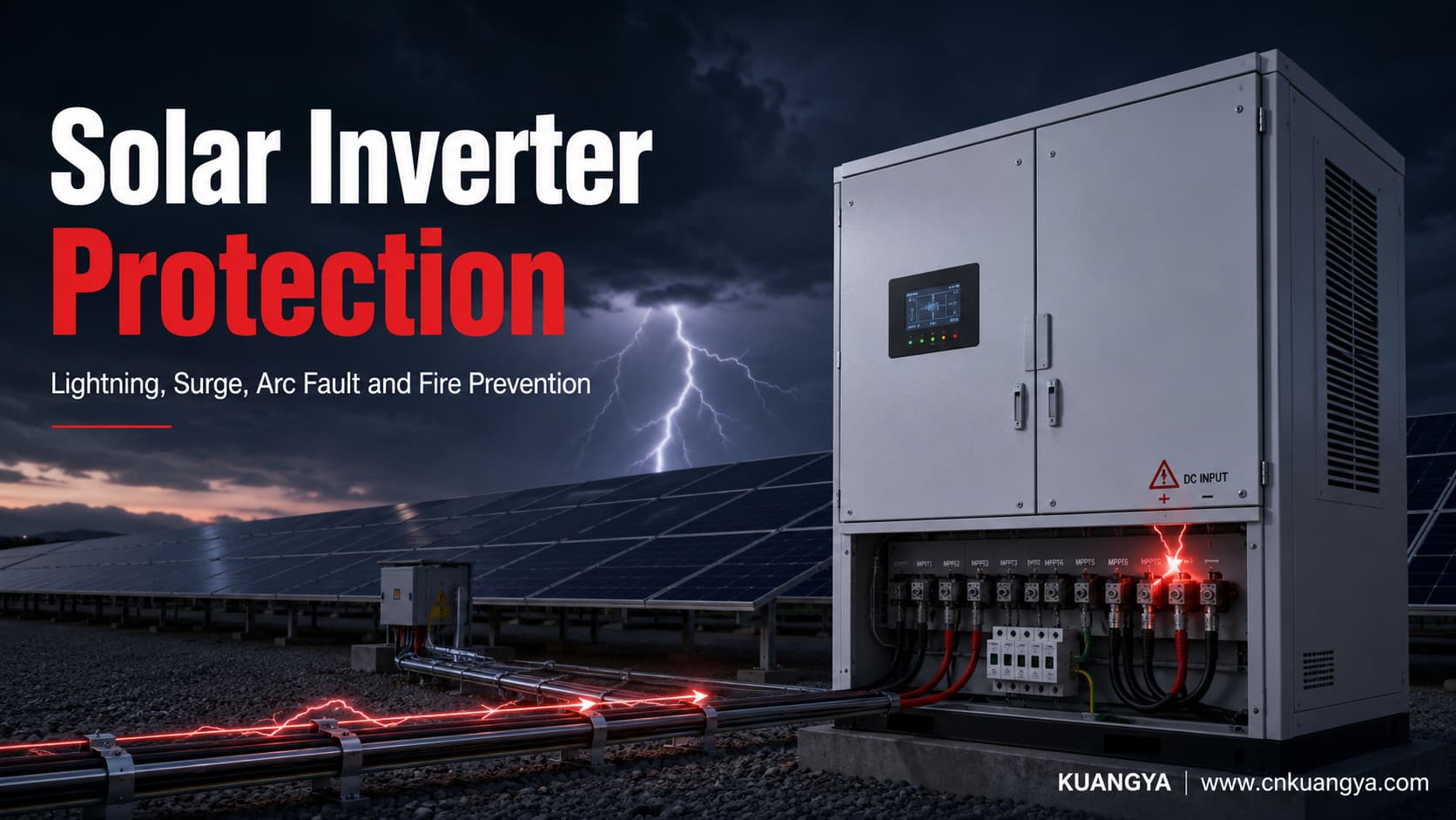
A solar inverter is usually the most electrically complex component in a photovoltaic system. It contains power semiconductors, DC-link capacitors, control boards, communication circuits, filters, relays, sensors, and grid-interconnection electronics.
These components can be damaged by lightning-induced surges, switching transients, reverse current, insulation faults, overheating, loose connections, DC arcs, ground faults, or incorrectly coordinated protection devices.
Effective Protection de l'onduleur solaire therefore cannot depend on a single fuse, circuit breaker, or surge protective device. It requires a coordinated protection system covering the PV array, DC cables, combiner boxes, inverter inputs, AC outputs, communication lines, earthing system, and potential fire zones.
This guide explains how engineers, electricians, EPC contractors, and plant operators can design that system. It also explains why some inverters continue to fail even when an SPD or fuse has already been installed.
Effective inverter protection should be designed as part of a complete Solar PV protection strategy that coordinates surge protection, overcurrent isolation, arc-fault control, and fire mitigation.
Solar Inverter Protection is the coordinated control of overvoltage, overcurrent, insulation failure, electric arcs, overheating, fire, and unsafe disconnection around a PV inverter.
The inverter is connected to at least two electrically different systems. Its DC terminals receive energy from PV strings, while its AC terminals connect to a distribution board, transformer, microgrid, or utility network.
Many modern inverters also have RS-485, Ethernet, meter, sensor, remote-shutdown, or weather-station connections. Each conductive path can carry transient energy into sensitive electronic circuits.
A lightning surge may enter through the PV array and DC cabling. It may also arrive through the AC network after a nearby strike affects overhead or underground distribution equipment.
Switching events from transformers, motors, capacitor banks, generators, or utility protection equipment can create transient overvoltage on the AC side. These events may occur without visible lightning.
Communication cables create another entry path. An inverter may have correctly selected power-circuit SPDs but still suffer damage through an unprotected monitoring or control line.
A circuit can comply with basic overcurrent requirements while still exposing inverter electronics to damaging impulse voltage.
A fuse is designed to interrupt excessive current under defined time-current conditions. It does not normally clamp a short microsecond-scale voltage impulse.
An SPD limits transient voltage and diverts surge current. It is not intended to replace a fuse, circuit breaker, isolator, ground-fault detector, or arc-fault protection device.
Engineers who need a device-level comparison can review the key differences between a DC fuse and DC SPD before defining the inverter protection architecture.
This distinction is central to effective Inverter Electrical Protection.
| Hazard | Common entry point or cause | Possible inverter damage | Primary protection layer |
|---|---|---|---|
| Lightning surge | PV array, DC cables, AC grid, data cable | Semiconductor breakdown, control-board damage, insulation failure | Coordinated SPDs and lightning protection |
| Switching transient | Transformer, grid switching, motors, capacitor banks | DC-link stress, relay damage, communication failure | AC SPD and equipment coordination |
| Courant inverse | Parallel PV strings or faulted string | Cable overheating, module or connector damage | gPV fuses and correct string design |
| Court-circuit | Damaged cable, failed equipment, wiring error | High thermal and mechanical stress | Fuse or circuit breaker |
| Series arc | Loose connector, poor crimp, broken conductor | Localized heating and fire | Arc detection, correct connectors and workmanship |
| Parallel arc | Damaged insulation between conductors | Sustained high-energy fault | Insulation protection and fault interruption |
| Ground fault | Insulation degradation, moisture, damaged cable | Shock, fire, inverter trip | Insulation monitoring and ground-fault protection |
| Internal overheating | Blocked ventilation, high ambient temperature, failed fan | Capacitor aging, semiconductor failure, fire | Thermal management and maintenance |
| Cabinet fire | Electrical fault that develops into ignition | Total inverter loss and fire spread | Detection, isolation, and approved suppression |
IEC 62548-1:2023 establishes PV-array design requirements covering DC wiring, electrical protection devices, switching, earthing provisions, and power conversion equipment. IEC 60364-7-712 addresses electrical-installation requirements associated with PV power-supply installations. Engineers should confirm the applicable editions and local adoption before finalizing a design.
Inverters contain components that are sensitive to voltage, temperature, humidity, contamination, vibration, and cyclic electrical stress.
NREL-related reliability research has repeatedly identified inverters as a leading source of PV hardware failures and associated energy loss. A failure-mode analysis presented through the U.S. Department of Energy’s OSTI database describes inverter reliability as a limiting factor in overall PV system reliability.
This does not mean every inverter failure is caused by poor inverter quality. In many cases, the failure begins outside the inverter through unsuitable installation, defective connectors, inadequate surge coordination, poor cooling, or uncorrected insulation faults.
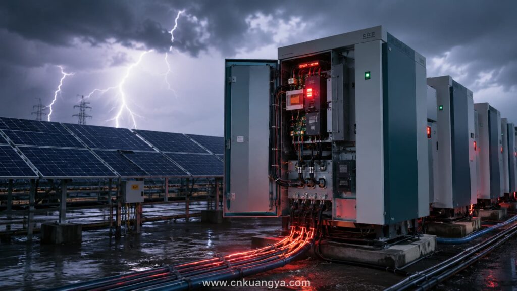
Lightning does not need to strike a solar array directly to damage an inverter.
A nearby strike can induce voltage in long PV conductors, earthing systems, metal structures, communication cables, and AC power lines. The resulting transient may reach the inverter before an upstream protective device operates.
A direct lightning strike transfers a portion of lightning current into the structure or electrical system. It represents the highest-energy event and normally requires a complete lightning protection and equipotential-bonding assessment.
An indirect strike creates electromagnetic fields that induce transient voltage in nearby conductors. Large PV arrays are especially exposed because their cable routes can form extensive collection areas.
Switching surges are created by normal or abnormal power-system operations. They may be lower in energy than a direct lightning event, but repeated exposure can weaken MOVs, insulation, capacitors, and semiconductor junctions.
IEC TR 63227 specifically addresses protection of PV power-supply systems against the harmful effects of lightning strikes and surge voltages. IEC 61643-32 provides principles for selecting, installing, and coordinating SPDs on PV DC circuits up to 1,500 V and on the associated AC side.
A transient overvoltage may exceed the withstand capability of input components before the inverter registers a normal fault.
Possible results include:
Surge damage is not always visible. A semiconductor may remain operational after an impulse but have reduced electrical margin, making it more likely to fail during the next high-temperature or high-load event.
A study of extreme-weather impacts on utility-scale PV plants found that storm-related maintenance records frequently involved lightning and flooding. In the examined records, inverter-level tripping associated with lightning represented 23% of the commonly observed storm issues, while site-level recloser trips and grid outages were also recorded.
An Australian Renewable Energy Agency performance report also recorded suspected lightning-surge damage at multiple sites. The affected equipment included cluster controllers, inverter communication cards, network switches, and communication surge arresters.
These cases show why Lightning Protection for Solar Systems must cover power, control, and communication circuits rather than only the inverter’s main AC terminals.
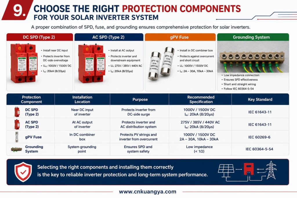
A Solar Inverter SPD is a surge protective device selected and installed to limit transient overvoltage before it exceeds the inverter’s insulation or electronic withstand level.
IEC 61643-31 applies to SPDs used on the DC side of PV installations up to 1,500 V DC. It defines requirements and test methods for devices intended to limit surge voltage and divert surge current.
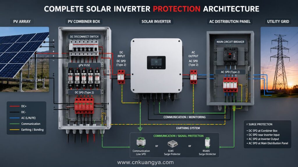
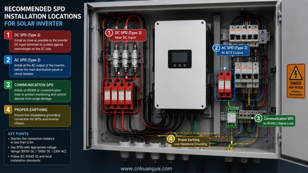
One SPD at the main distribution board may not protect the entire PV system. Long conductors between the array, combiner box, inverter, transformer, and main panel can develop additional induced voltage.
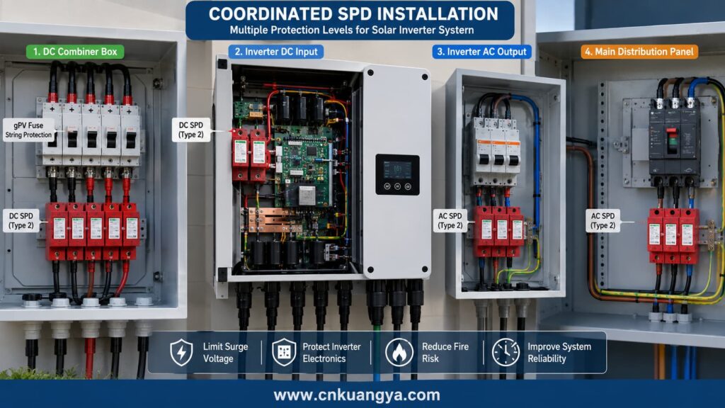
For many systems, protection has to be coordinated at more than one location.
| Protection location | Main purpose | Typical design concern |
|---|---|---|
| PV string or array combiner box | Intercept surges arriving from the array | Maximum PV voltage and earthing arrangement |
| Entrée DC de l'onduleur | Reduce residual voltage reaching DC electronics | Distance from upstream SPD and inverter withstand |
| Sortie AC de l'onduleur | Protect against grid-side and switching transients | AC system voltage and conductor configuration |
| Main AC distribution board | Divert incoming building or utility surges | Service type and lightning exposure |
| Communication interface | Protect RS-485, Ethernet, sensor, or meter lines | Signal voltage, bandwidth, shielding, earthing |
| External monitoring cabinet | Protect data loggers and auxiliary supplies | Separate power and signal protection |
A complete design should also consider whether an external lightning protection system is present and whether adequate separation distance can be maintained between lightning conductors and PV wiring.
A Type 1 SPD is designed to handle partial lightning current under defined impulse conditions. It is generally considered where direct lightning-current exposure is possible, including installations associated with an external lightning protection system.
A Type 2 SPD is intended mainly for induced lightning surges and switching transients. It is commonly used near distribution equipment, PV combiner boxes, and inverter terminals.
Some devices combine Type 1 and Type 2 characteristics. The correct choice must be based on the lightning protection assessment, conductor routing, installation category, local rules, and equipment coordination.
| SPD classification | Main exposure | Common PV application |
|---|---|---|
| Type 1 | Courant de foudre direct partiel | Building entry or circuits exposed through an LPS |
| Type 2 | Induced lightning and switching surges | Combiner boxes, inverter DC side, AC distribution |
| Type 1+2 | Combined exposure requirements | High-risk sites requiring compact coordinated protection |
| Signal-line SPD | Data and control transients | RS-485, Ethernet, sensors, meters |
Installing a Type 1 device everywhere does not automatically produce better protection. A device must be correctly matched to system voltage, earthing configuration, prospective surge current, required protection level, and upstream or downstream SPDs.
For a PV DC SPD, the Ucpv rating must remain suitable for the highest voltage that can appear under normal system conditions.
The design should calculate the maximum corrected open-circuit voltage at the site’s lowest expected module temperature. Using only the inverter’s nominal DC voltage can lead to an underspecified SPD.
A practical calculation workflow is provided in our engineering guide on comment dimensionner un parafoudre CC pour une installation photovoltaïque.
The SPD’s voltage protection level indicates the residual voltage under defined test conditions.
A lower protection level can improve protection, but only when it is compatible with system operating voltage, temporary overvoltage behavior, insulation coordination, and the complete SPD design.
The values must reflect the installation’s lightning and surge environment. Selecting an SPD only because it has a high printed kA value is not a complete engineering method.
The SPD assembly must be able to withstand the available fault current until its disconnecting mechanism or backup protective device operates.
The manufacturer’s required backup fuse or breaker must be coordinated with the installation. Omitting this coordination can turn an SPD failure into a thermal event.
PV systems may be floating, functionally earthed, transformer-isolated, or transformerless. The SPD connection mode must be compatible with the actual system.
An incorrect connection configuration may leave one surge path insufficiently protected or place continuous stress on an SPD component.
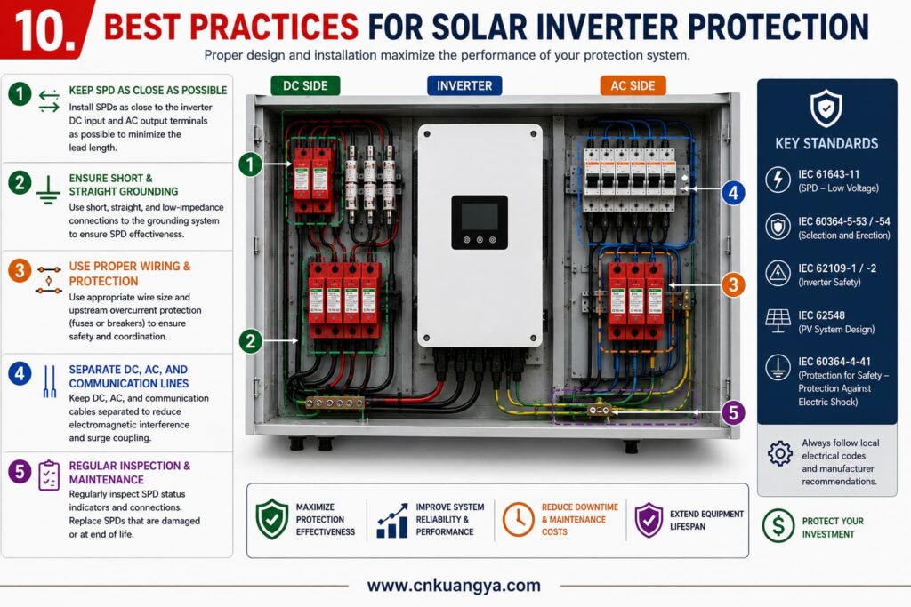
An SPD cannot protect the inverter effectively when it is connected through long, looped, or poorly routed conductors.
Surge current has a high rate of change. Even a conductor with low power-frequency resistance can develop significant inductive voltage during an impulse.
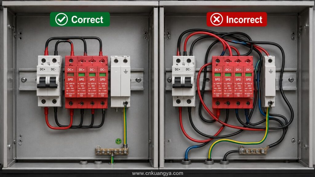
SPD conductors should therefore be as short, straight, and direct as practical. Large loops, unnecessary bends, and separate earthing routes increase the residual voltage appearing at the inverter.
The SPD should also be installed close to the equipment or protection boundary it serves. Where distances are substantial, a second coordinated SPD may be needed.
RS-485 and Ethernet ports often operate at much lower voltages than the inverter’s power terminals.
A transient that is harmless to an AC power circuit may be destructive to a communication transceiver. Signal-line SPDs should match the normal signal voltage, transmission frequency, connector type, shielding arrangement, and earthing concept.
The communication SPD and power SPD should connect to a well-designed equipotential bonding system. Independent “earth” connections with high potential difference can redirect surge current through the inverter.
A Solar Inverter Fuse protects conductors and equipment against defined overcurrent conditions. It does not perform the same function as an SPD.
The fuse must operate before fault energy exceeds the thermal withstand of the protected cable, connector, holder, module, combiner-box busbar, or inverter input circuit.
PV circuits operate with direct current and can remain energized whenever sunlight is available.
Unlike AC current, DC current does not pass naturally through zero every half-cycle. Interrupting a DC fault therefore requires a fuse with appropriate arc-extinguishing capability and voltage rating.
IEC 60269-6 provides supplementary requirements for fuse-links used to protect PV strings and arrays in circuits up to 1,500 V DC. The standard includes PV-specific fuse requirements rather than treating the application as an ordinary AC load.
In North American applications, relevant PV balance-of-system standards may include UL 248-19 for PV fuses, UL 489B for PV circuit breakers, and associated fuse-holder or disconnect standards.
A gPV fuse is designed for photovoltaic-source circuits. It can interrupt fault currents within its tested operating range while withstanding continuous PV current and environmental stress.
Its main functions may include:
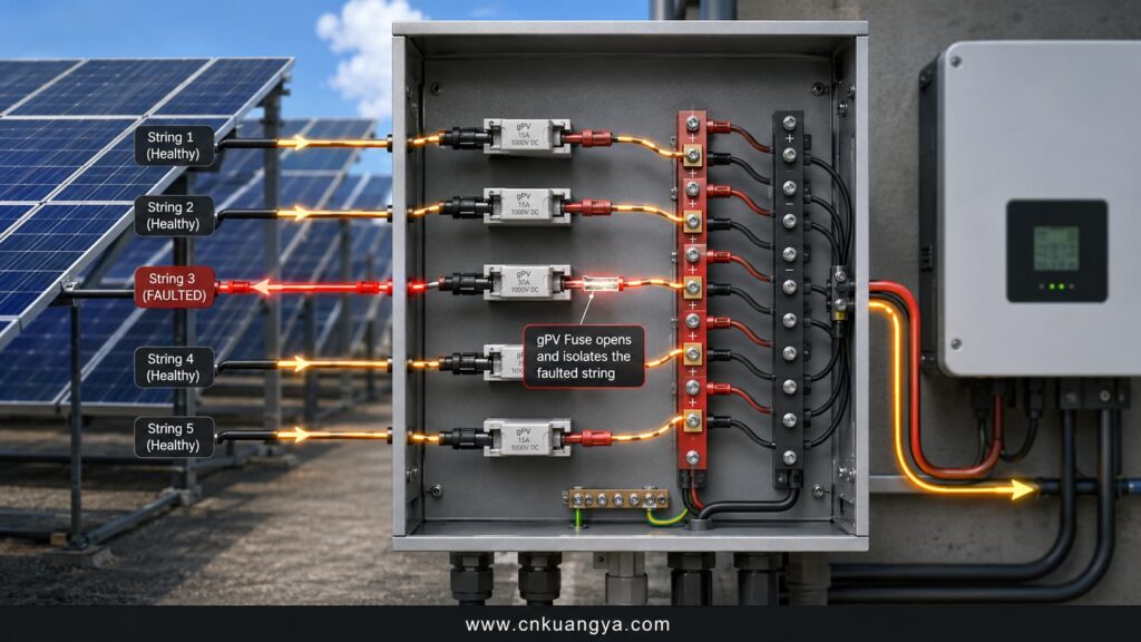
A fuse does not guarantee protection against every DC arc. A high-resistance series arc may draw less current than the fuse rating and continue generating intense localized heat.
String fuses become important when current from the remaining parallel strings can exceed the reverse-current withstand of a faulted string, module, cable, or connector.
The engineer should calculate the maximum possible reverse current rather than applying one fuse value to every array.
For a structured selection process, use this DC fuse sizing guide to verify voltage rating, continuous current, breaking capacity, and temperature derating.
Variables include:
Some small arrays may not require individual string fuses if the maximum reverse current cannot exceed equipment limits. That decision should be documented rather than assumed.
| Paramètres | Engineering question |
|---|---|
| Rated DC voltage | Is the rating at least equal to the highest calculated system voltage? |
| Courant nominal | Can the fuse carry expected continuous current without nuisance operation? |
| Minimum operating current | Will the fuse clear the lowest credible damaging reverse current? |
| Capacité de rupture | Can it safely interrupt the available DC fault current? |
| Utilization category | Is it specifically suitable for PV applications, such as gPV? |
| Module limit | Does it remain within the module’s maximum series-fuse rating? |
| Cable protection | Does it protect the smallest conductor and connector in the circuit? |
| Temperature derating | Have enclosure and ambient temperatures been considered? |
| Holder compatibility | Is the holder rated for the same DC voltage, current, and fuse format? |
| Coordination | Does it coordinate with downstream and upstream protective devices? |
A correctly rated fuse link can still overheat in a poor-quality or incorrectly installed holder.
Heating may develop from weak contact pressure, contamination, corrosion, incorrect fuse dimensions, loose terminals, undersized conductors, or operation near the holder’s thermal limit.
Thermographic inspections should include the fuse holder, terminals, cable lugs, busbars, and adjacent conductors. Replacing only the fuse link will not solve a high-resistance contact fault.
| Dispositif | Main function | Clears overload or short circuit? | Limits voltage surge? | Provides visible isolation? |
|---|---|---|---|---|
| fusible gPV | PV overcurrent protection | Oui | Non | Only after removal or with switch-fuse design |
| Disjoncteur DC | Overcurrent interruption and switching | Yes, when correctly rated | Non | Depends on design |
| Isolateur DC | Safe manual disconnection | Normally no | Non | Oui |
| DC SPD | Transient overvoltage limitation | Non | Oui | Non |
| Arc-fault device | Detect and interrupt certain arc conditions | Not a general overcurrent device | Non | May initiate interruption |
| Ground-fault protection | Detect leakage or insulation fault | For defined fault conditions | Non | May initiate disconnection |
| Fire suppression device | Limit fire after ignition | Non | Non | Non |
A common design error is treating these devices as interchangeable. They are complementary protection layers.
The inverter’s AC output should be coordinated with the cable, distribution board, transformer, utility requirements, fault level, and inverter manufacturer’s instructions.
The AC circuit breaker or fuse must be capable of interrupting the prospective fault current at the installation point.
The design should also consider residual-current protection, anti-islanding, grid-code functions, transformer inrush, neutral configuration, and protection selectivity.
UL photovoltaic inverter certification covers key requirements including UL 1741 for inverter and interconnection equipment and UL 1699B for photovoltaic DC arc-fault circuit protection.
A DC arc can maintain an extremely hot plasma path without drawing enough current to operate a conventional fuse.
This is why fuse protection alone is not sufficient for complete Protection de l'onduleur solaire.
A series arc forms when the intended current path becomes discontinuous.
Typical causes include:
The operating current flows through the arc. Because the load and inverter limit that current, it may remain below the fuse operating threshold.
A parallel arc forms between conductors at different potentials or between a live conductor and earth.
It may result from insulation damage, crushed cables, moisture ingress, rodent damage, connector failure, or two independent ground faults.
A parallel arc can receive energy from multiple strings. Simply turning off the inverter may not remove all energy from the fault because the PV modules remain generating sources.
An NREL-supported research project documented the Bakersfield rooftop PV arc-fault fire and demonstrated the destructive potential of faulty DC wiring and sustained arcing.
The report explained that PV arc faults can occur in module interconnections, junction boxes, conductors, and connectors between modules and the inverter. It also stated that forensic investigations of PV fires had frequently identified series arc faults or ground faults.
The Bakersfield incident demonstrates that an arc can begin well before the inverter itself burns. Protecting only the inverter enclosure leaves the upstream DC circuit exposed.
The same risk chain should also be evaluated through a dedicated solar combiner box fire protection strategy because faults originating upstream can propagate toward inverter DC inputs.
IEC 63027:2023 applies to equipment used to detect and optionally interrupt DC arcs in PV circuits. It includes testing for series-arc detection and the response time of interruption equipment.
Arc-fault detection may be integrated into the inverter or installed as a separate protective function.
However, arc-fault protection should not be used to compensate for poor workmanship. Correct connector assembly, cable management, torque control, inspection, and compatible components remain the first line of defense.
Connectors that appear physically compatible may have different contact materials, spring forces, tolerances, sealing systems, or crimp requirements.
A mixed connection can initially pass a continuity test but develop increasing resistance after moisture exposure, temperature cycling, mechanical loading, or prolonged current flow.
A 2025 NREL-associated report on PV connector failures emphasized the safety, liability, maintenance-cost, and energy-production consequences of poorly installed, mismatched, or poorly manufactured connectors.
For critical PV circuits, connector make, model, tooling, crimp procedure, and installation records should be controlled as engineering data.
Insulation faults may occur between a live conductor and module frame, mounting structure, enclosure, cable tray, or earth.
Moisture, ultraviolet degradation, damaged cable jackets, contamination, rodents, poor cable support, and incorrectly installed glands can contribute to insulation failure.
Inverter insulation-monitoring alarms must be investigated. Repeatedly resetting an insulation fault without locating its source can allow a second fault to create a dangerous parallel-current path.
An inverter installed in direct sun, a poorly ventilated room, or a dusty enclosure may operate near its thermal limit.
High temperature accelerates the aging of capacitors, fans, insulation, seals, display components, and power semiconductors. It can also reduce the current-carrying capability of nearby cables and protection devices.
IEA PVPS operation and maintenance guidance notes that unsuitable operating conditions can increase the probability of major inverter-electronics damage. It also reports inverter-electronics failures as a common inverter failure type in the Atacama Desert environment.
| Warning sign | Possible cause | Required response |
|---|---|---|
| Repeated insulation alarm | Cable or connector leakage, moisture, damaged module | Test and locate the fault before restarting |
| Arc-fault alarm | Loose connection, incompatible connector, damaged cable | Isolate, inspect, and replace damaged parts |
| Burnt smell | Overheated terminal, PCB, fuse holder, or contactor | De-energize and conduct thermal and visual inspection |
| Brown or discolored insulation | Long-term high-resistance heating | Replace damaged conductors and correct termination |
| SPD status indicator changed | SPD degradation or disconnection | Replace the module and investigate the surge event |
| Unexplained inverter restart | Grid disturbance, surge, internal thermal issue | Review event logs and power-quality records |
| Communication failure after storm | Signal-line surge or bonding issue | Inspect signal SPDs, grounding, and interface boards |
| One string producing less current | Fuse, connector, module, or cable fault | Perform string-current and insulation testing |
| Hot fuse holder | Loose contact, overload, poor holder, wrong fuse | Isolate and replace the defective assembly |
| Rising enclosure temperature | Blocked airflow, fan failure, high ambient | Restore cooling and verify loading |
Electrical protection should prevent ignition whenever possible.
Fire suppression becomes relevant when an electrical fault has already generated enough heat to ignite insulation, plastic components, filters, cable materials, or contamination inside an enclosure.
An aerosol fire suppression device cannot correct an incorrectly rated fuse, undersized SPD, loose terminal, damaged cable, or failed isolator.
It should be treated as a final mitigation layer after prevention, detection, and electrical isolation.
The correct protection hierarchy is:
Small-enclosure fire suppression may be useful in:
The device should be matched to the protected volume, enclosure geometry, expected fire class, ventilation openings, temperature range, activation method, and local approval requirements.
Condensed aerosol systems create an extinguishing aerosol that interferes with the fire’s chemical reaction.
For enclosure-level applications, engineers can review how an aerosol fire extinguisher for electrical cabinets works before assessing protected volume, activation method, ventilation, and equipment compatibility.
They can be compact and may be considered for enclosed electrical spaces where installing cylinders, pipework, and nozzles is difficult.
NFPA 2010 contains minimum requirements for the design, installation, testing, inspection, operation, and maintenance of fixed aerosol fire-extinguishing systems. ISO 15779 addresses component requirements and recommendations for system design, installation, testing, maintenance, and safety of condensed aerosol systems.
Aerosol systems must be selected according to their certified application. Engineers should not assume that any small aerosol generator is automatically suitable for live electrical equipment or every enclosure type.
| Design question | Pourquoi c'est important |
|---|---|
| What is the net protected volume? | Agent quantity depends on the enclosure volume and design concentration |
| Is the enclosure sealed or ventilated? | Openings can reduce agent retention |
| What materials could ignite? | Cable, plastic, oil, filters, and electronics may require different assessment |
| How is the unit activated? | Thermal, electrical, or combined activation changes response behavior |
| Will power be isolated? | Continued electrical energy can cause re-ignition |
| Is the unit listed or certified? | Project acceptance may require third-party approval |
| Can residue affect equipment? | Cleanup and equipment compatibility must be evaluated |
| Is the enclosure normally occupied? | Exposure limits and safety procedures may apply |
| Can maintenance staff access it safely? | Inspection and replacement must be practical |
| What happens after discharge? | Lockout, ventilation, investigation, and replacement procedures are required |
The suppression device should be positioned so that its discharge is not obstructed by cables, metal plates, filters, or large components.
It should not direct high-temperature discharge onto sensitive wiring unless the product has been specifically evaluated for that arrangement.
Placement near the most probable ignition zone can improve response. Likely zones include DC terminals, fuse holders, contactors, power modules, cable entries, and densely wired control sections.
The manufacturer’s clearance and mounting instructions take priority over generic positioning rules.
A high-quality design should generate an alarm and initiate appropriate shutdown when fire or abnormal heat is detected.
Depending on the system, the sequence may include:
The design must recognize that opening the AC side does not remove PV voltage from upstream DC cables. Isolation has to be considered on both sides.
A UK government-funded BRE investigation recorded 80 fire incidents involving PV systems. The researchers classified poor installation as the probable root cause in 21 records, system-design issues in six, faulty products in three, and the cause as unknown in 28; the report cautioned that the dataset was limited.
The same investigation included 33 historical incidents and 47 incidents investigated through site visits or desk studies. The findings support a prevention-first approach based on installation control, documentation, inspection, and maintenance.
A 2026 UK literature review also noted increasing PV-related fire reports in several markets, including a fivefold rise in reported incidents in New South Wales between 2016 and 2021. These figures should be interpreted in the context of rapidly increasing PV deployment and different national reporting systems.
The following process can be used during system design, technical review, commissioning, or retrofit assessment.
Document:
Protection cannot be coordinated without an accurate single-line diagram.
Calculate string open-circuit voltage at the lowest expected module temperature.
Compare the result with the ratings of:
The lowest-rated component defines the practical system limit.
Review local lightning density, site exposure, building height, external lightning protection, overhead lines, array size, conductor lengths, and equipment value.
Determine whether Type 1, Type 2, or combined SPDs are required at each protection boundary.
The assessment should cover the PV DC side, AC side, auxiliary supplies, and communication system.
Select SPDs based on actual system voltage and earthing configuration.
Vérifier :
Document the distance between each SPD and the equipment it protects.
Determine the maximum reverse current into a faulted string and the maximum prospective fault current at each protective device.
Select a gPV fuse or DC circuit breaker that protects the cable and equipment without nuisance operation.
Confirm the fuse holder’s voltage, current, power-dissipation, temperature, and breaking-capacity compatibility.
Use one compatible connector system and the specified crimp tools.
Record torque values, connector batches, cable type, polarity tests, insulation-resistance results, and string-current measurements.
Use arc-fault detection where required by the applicable code or project specification.
Install the inverter in accordance with required clearances and environmental limits.
Avoid locations with direct solar heating, obstructed airflow, corrosive contamination, water exposure, or concentrated dust unless the equipment is designed for those conditions.
Monitor fan condition, air filters, heatsinks, terminal temperature, and enclosure temperature.
For high-value or remote installations, evaluate smoke, heat, or arc detection and enclosure-level suppression.
Ensure the suppression system is appropriately designed, tested, installed, and maintained.
Integrate fire activation with alarm transmission and electrical shutdown where technically appropriate.
Solar Inverter Protection is incomplete until the installation is tested.
Commissioning should verify:
IEC 62446-1 defines documentation and commissioning information for grid-connected PV installations, while IEC 62446-2 addresses preventive, corrective, and performance-related maintenance.
Inspection intervals should be adjusted for climate, manufacturer requirements, insurance conditions, site criticality, and fault history.
| Inspection activity | Typical timing | Main objective |
|---|---|---|
| Remote alarm and performance review | Daily or continuously | Detect trips, low output, insulation alarms, or overheating |
| Visual inverter inspection | Monthly to quarterly | Identify contamination, water ingress, damaged glands, or blocked ventilation |
| SPD status check | Quarterly and after major storms | Identify disconnected or end-of-life SPD modules |
| Fuse and holder inspection | Six to twelve months | Check discoloration, corrosion, contact pressure, and heat damage |
| Thermographic inspection | During representative high load | Locate high-resistance connections and uneven heating |
| Torque verification | According to manufacturer and risk | Confirm critical terminations remain secure |
| Insulation-resistance testing | Periodically and after relevant faults | Identify cable, connector, or module insulation deterioration |
| Earthing and bonding test | Periodically and after lightning work | Verify the surge-current and fault-current path |
| Communication protection inspection | After communication faults or storms | Check signal SPDs, shields, bonding, and data equipment |
| Fire suppression inspection | According to certification and manufacturer | Confirm mounting, service life, activation circuit, and protected volume |
Do not assume that a running inverter has escaped damage.
After a significant storm, check:
A degraded SPD may remain connected but have reduced future capability. Replacement criteria must follow the manufacturer’s instructions.
A B2B enquiry should include more than voltage and current.
For an SPD, specify:
For a Solar Inverter Fuse, specify:
For cabinet fire suppression, specify:
Kuangya supports EPC contractors, panel builders, PV-system integrators, and electrical distributors with PV SPDs, gPV fuses, fuse holders, and compact electrical-cabinet fire-protection solutions.
Component selection should always be confirmed against the project’s single-line diagram, environmental conditions, inverter instructions, and applicable electrical code.
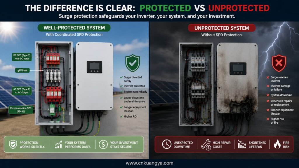
Fiable Protection de l'onduleur solaire is created through coordination, not through a single protective device.
The SPD limits lightning and switching overvoltage. The fuse or breaker interrupts damaging overcurrent. The isolator provides controlled disconnection. Arc and ground-fault protection detect faults that may not operate a conventional fuse.
Correct connectors, cable routing, earthing, thermal management, commissioning, and maintenance prevent small defects from developing into inverter failure or fire.
Fire suppression provides an additional final layer for enclosed electrical equipment. It should limit the consequences of ignition but should never be used to justify weak electrical design.
For new PV projects, inverter protection should be designed before equipment procurement. For operating plants, the most effective first step is a coordinated audit of DC protection, AC protection, SPD condition, fuse coordination, connectors, alarms, and thermal performance.
Contact Kuangya for project-based selection of PV surge protective devices, gPV fuse protection, OEM electrical components, and compact cabinet fire-protection solutions.
Usually, internal inverter protection should not automatically be treated as a complete external lightning-protection system.
Internal components may provide limited protection for defined test conditions. External coordinated SPDs reduce the surge energy and residual voltage reaching the inverter and are easier to inspect or replace after a surge.
In many installations, both sides require assessment because the inverter can receive surges from the PV array and the AC network.
The final requirement depends on lightning exposure, cable length, external lightning protection, utility configuration, inverter design, and local electrical rules.
The SPD’s Ucpv rating must be compatible with the highest calculated PV open-circuit voltage under the lowest expected site temperature.
Do not select it only from nominal array voltage. The earthing arrangement and temporary overvoltage conditions must also be considered.
No. A fuse responds to excessive current over its time-current operating range.
A lightning transient may reach a destructive voltage in microseconds without producing the type of sustained current needed to operate the fuse. An appropriately selected SPD is required for surge limitation.
A series arc can be current-limited by the inverter and PV string.
The arc may generate dangerous localized heat while remaining below the fuse operating current. Arc-fault detection, connector quality, and correct installation are therefore necessary.
Communication circuits use low-voltage electronic components and may be connected to long external cables.
Surges can enter through RS-485, Ethernet, sensor, meter, or auxiliary-power wiring. Signal-line SPDs, shielding, bonding, and correct cable routing should be assessed.
Only when the device is suitable for the enclosure, protected volume, equipment type, activation method, and applicable approval requirements.
The inverter manufacturer, suppression-system instructions, ventilation openings, electrical isolation, residue, and service access must be considered.
Possible causes include insulation leakage, unstable grid voltage, overheating, arc-fault detection, degraded connectors, SPD failure, communication errors, or intermittent internal faults.
The event log, insulation resistance, string currents, grid measurements, thermal condition, and protection-device status should be checked before resetting the inverter repeatedly.
