Zone industrielle WengYang Yueqing Wenzhou 325000
Heures de travail
Du lundi au vendredi : de 7h00 à 19h00
Le week-end : 10H00 - 17H00
Zone industrielle WengYang Yueqing Wenzhou 325000
Heures de travail
Du lundi au vendredi : de 7h00 à 19h00
Le week-end : 10H00 - 17H00

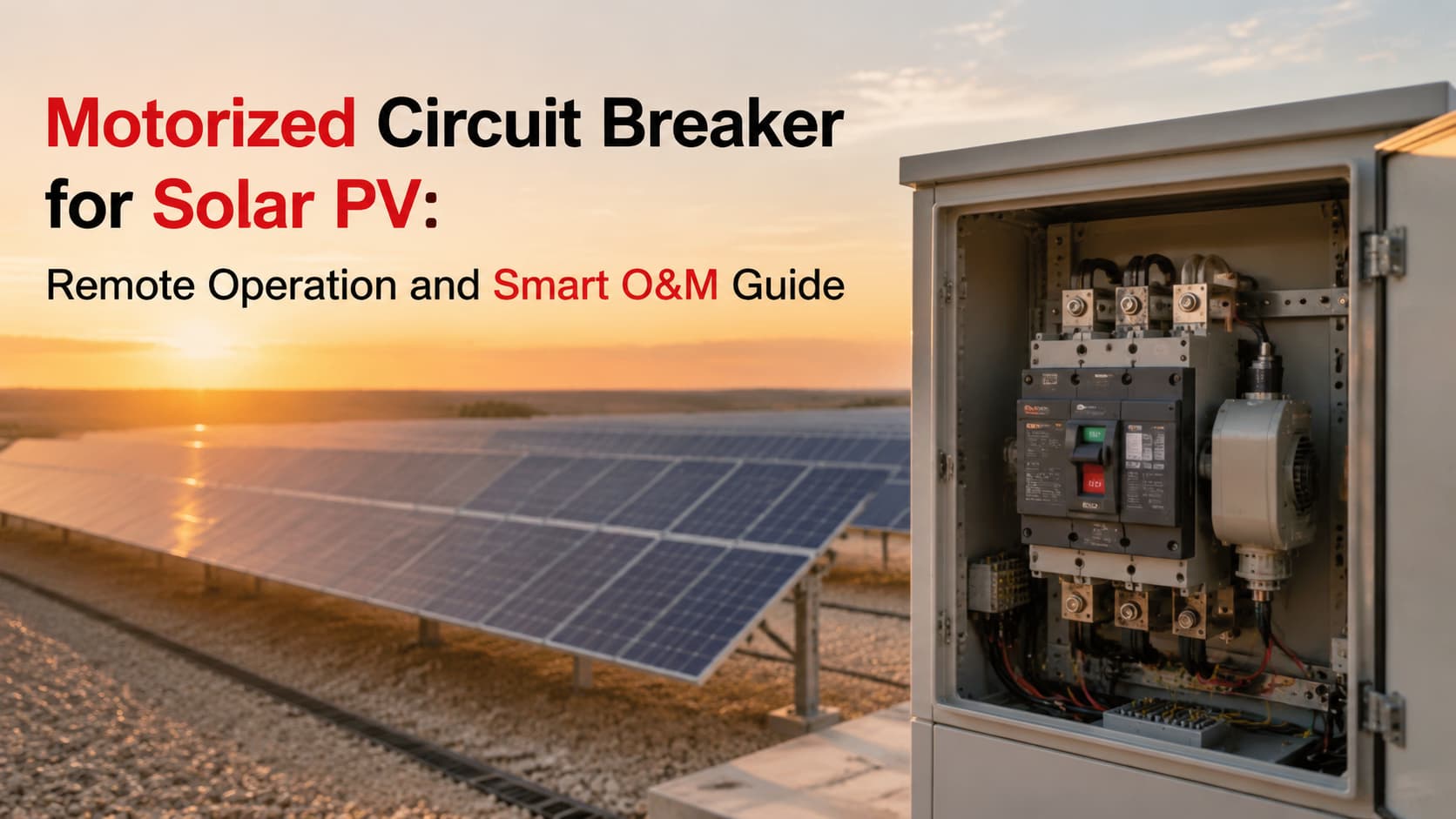
Les centrales solaires photovoltaïques se développent rapidement. Un seul site à l'échelle industrielle peut désormais s'étendre sur des centaines d'hectares, avec des milliers de boîtiers de jonction, d'onduleurs et d'armoires de distribution répartis sur des terrains isolés. À mesure que les installations grandissent, le coût et la complexité de l'envoi de techniciens pour exploiter et entretenir ces équipements augmentent avec chaque mégawatt. Le contrôle à distance est passé d'une commodité à une nécessité, et au cœur de ce changement se trouve le disjoncteur motorisé pour le solaire photovoltaïque — un dispositif qui transforme un interrupteur physique en une commande exécutée depuis une salle de contrôle, parfois située à des centaines de kilomètres.
Ce guide explique le rôle des disjoncteurs motorisés dans les systèmes photovoltaïques, leur fonctionnement, leur emplacement côté courant continu (DC) et courant alternatif (AC), et pourquoi ils deviennent la colonne vertébrale de l'exploitation et de la maintenance solaires intelligentes.
Pendant des décennies, actionner un disjoncteur signifiait qu'une personne devait s'en approcher, saisir une poignée et pousser. Sur un système résidentiel en toiture, cela convient. Sur un parc solaire de 500 MW avec des boîtiers de jonction dispersés dans un désert, il s'agit d'un sérieux goulot d'étranglement opérationnel.
Les problèmes liés à l'exploitation manuelle traditionnelle s'aggravent à mesure que la taille de l'installation augmente :
La télécommande résout ces problèmes en déplaçant l'action de commutation vers un écran SCADA, un automate programmable (API) ou un système de gestion de l'énergie. La comparaison ci-dessous concrétise cet écart :
| Objet | Opération manuelle | Opération motorisée |
|---|---|---|
| Lieu d'opération | Sur site, au niveau de l'appareil | Salle de contrôle ou terminal distant |
| Temps de réponse | De quelques minutes à plusieurs heures | Secondes |
| Coût de la maintenance | Coûts élevés de main-d'œuvre et de déplacement | Réduction des visites sur site |
| Capacité d'automatisation | Aucun | Intégration complète avec la logique de contrôle |
| Contrôle à distance | Impossible | Fonctionnalité standard |
La différence n'est pas négligeable. En cas de défaut, réduire le temps d'isolement de deux heures à dix secondes protège l'équipement, limite les temps d'arrêt et permet au reste du réseau de continuer à produire.
Un disjoncteur motorisé n'est pas simplement un disjoncteur équipé d'un moteur ajouté. Il s'agit d'un ensemble de commutation intégré conçu pour effectuer à distance ce qu'un technicien ferait manuellement : ouvrir et fermer un circuit sur commande, tout en conservant l'indice de protection d'un disjoncteur conventionnel et la contrôlabilité d'un dispositif automatisé.
Dans le contexte du solaire photovoltaïque, sa fonction est spécifique : assurer une commutation et une protection sûres et contrôlables à distance aux points clés de la chaîne de distribution CC et CA. Un système complet comprend quatre éléments fonctionnels :
| Composant | Fonction |
|---|---|
| Disjoncteur | Protection contre les surintensités et les courts-circuits |
| Mécanisme de commande motorisé (opérateur motorisé) | Exécute les commandes d'ouverture/fermeture à distance |
| Contact auxiliaire | Envoie le retour d'état du disjoncteur au système de contrôle |
| API / SCADA | Émet des commandes et enregistre les opérations |
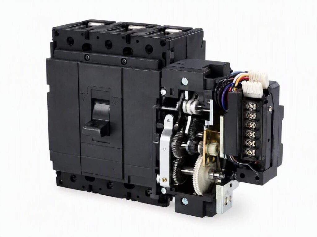
Le mécanisme de commande motorisé est le cœur du système. Il reçoit un signal électrique, le convertit en mouvement mécanique via un ensemble d'engrenages et de tringlerie, et actionne la manette du disjoncteur vers la position ouverte ou fermée. Les contacts auxiliaires confirment ensuite que le disjoncteur a réellement atteint l'état souhaité et renvoient cette information en amont. Cette boucle de rétroaction fermée est ce qui distingue un disjoncteur motorisé d'un simple interrupteur à distance : le système de contrôle connaît toujours la position réelle des contacts, et pas seulement la commande qu'il a envoyée.
Comprendre la séquence de fonctionnement aide les ingénieurs et les équipes d'approvisionnement à évaluer la compatibilité avec leur architecture de contrôle. Le processus comporte cinq étapes :
Étape 1 — Commande de contrôle. Le système API ou SCADA émet un signal d'ouverture ou de fermeture, généralement via un contact sec ou un module de sortie numérique.
Étape 2 — Activation du moteur. Le moteur d'entraînement de la commande motorisée est mis sous tension et commence à tourner.
Step 3 — Mechanical Transmission. Gears, cams, and linkages convert the motor’s rotation into the linear or rotary motion needed to move the breaker operating shaft.
Step 4 — Circuit Breaker Operation. The mechanism drives the breaker to its open or closed position, completing or interrupting the circuit.
Step 5 — Status Feedback. Auxiliary contacts change state and report the breaker’s new position back to the control system, closing the loop.
Video Demonstration: Remote Opening and Closing of Circuit Breaker Motor Operator Watch the motor operator drive the breaker through a complete open-close cycle — the mechanical transmission and contact action are visible in real time.
The critical detail is that this entire sequence happens in a fraction of a second, without a human hand on the device. And because the motor operator is mechanically coupled to the same operating shaft a technician would use manually, the protection tripping function of the breaker itself is never bypassed — if a fault occurs, the breaker trips on its protection curve regardless of motor state.
This is where motorized breakers earn their place in a PV design. They are not abstract automation concepts; they solve concrete switching problems on both the DC and AC sides, and increasingly in energy storage.
On the DC side, motorized breakers handle isolation and control between the PV array and the inverter. Typical installation points:
| Application | Objectif |
|---|---|
| Boîte combinée DC | Remote isolation of faulty strings without visiting the array |
| DC Distribution Cabinet | Centralized control of multiple array feeders |
| Battery Storage System (DC) | Safe rapid shutdown of battery circuits |
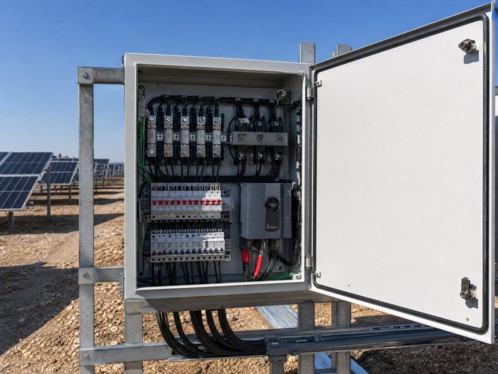
DC-side remote switching is especially valuable for fault isolation. A ground fault or arc event on a specific string can be disconnected from the control room, letting the rest of the boîte de raccordement continue operating instead of taking the whole box offline for a site visit.
On the AC side, motorized breakers manage the interface between inverters, distribution, and the grid:
| Application | Fonction |
|---|---|
| Inverter Output Cabinet | Remote switching of inverter feeders for maintenance or curtailment |
| Grid Connection Cabinet | Controlled connection and disconnection from the grid |
| AC Distribution Panel | Intelligent operation of downstream loads and feeders |
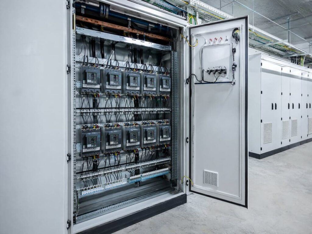
Grid-connection cabinets benefit most. Coordinated, remotely commanded switching lets operators comply with grid-code disconnect requirements within the time utilities demand — something manual operation simply cannot guarantee consistently. This same coordination principle extends to solar inverter protection, where breaker status and switching commands integrate into the inverter’s protection zone.
As solar projects increasingly pair generation with BESS (Battery Energy Storage Systems), motorized breakers take on a new role: managing the charge and discharge circuits of battery racks under EMS (Energy Management System) control. Remote isolation of battery strings is a safety requirement in many storage standards, and motorized operation allows the EMS to disconnect a degraded or overheating rack without dispatching a technician — a capability that matters most during thermal events when every second counts.
A modern solar plant is no longer just a generator. It is an intelligent energy system, and motorized breakers are the physical actuators that let software act on the hardware. The control hierarchy looks like this:
SCADA / EMS → PLC → Motor Operator → Disjoncteur → Retour d'information
At the top, SCADA and EMS platforms manage plant-wide logic — generation targets, grid dispatch commands, fault response. The PLC translates these high-level instructions into device-level commands. The motor operator executes. The breaker switches. Status flows back up the chain.

This architecture is what makes a solar plant “smart” rather than merely automated. It allows:
The result is a PV plant that can be operated, optimized, and audited from a single interface.
This is the section that answers the question every plant owner eventually asks: what is the actual return? The efficiency gains fall into four areas.
Routine switching and inspection no longer require a truck roll. Operators can verify status and perform switching remotely, cutting the number of physical visits to remote or hazardous locations dramatically.
When a fault occurs, the affected circuit can be isolated in seconds rather than the hours a site visit would take. That speed limits equipment damage, reduces fire risk, and shrinks generation losses.
Because breaker status and operation history are logged automatically, maintenance teams can plan interventions based on data — actuations, last operation date, fault history — instead of calendar-based inspection schedules.
For distributed and remote installations, motorized breakers make true unattended operation feasible. A small regional site can be monitored and controlled from a central O&M center, with on-site visits reserved for physical maintenance only.
| Traditional O&M | Intelligent O&M with Motorized Breakers |
|---|---|
| Inspection manuelle | Surveillance à distance |
| Local operation | Contrôle à distance |
| High labor cost | Reduced workload |
| Reactive fault response | Proactive, data-driven |
The cumulative effect: lower O&M cost per megawatt, higher availability, and safer operating conditions for staff.
A motorized breaker does not work in isolation. It is one node in a complete PV electrical protection system, and understanding that system helps with both design and troubleshooting.
| Dispositif | Function in the PV System |
|---|---|
| Fusible DC | Overcurrent protection on PV strings |
| DC SPD (Surge Protective Device) | Surge and lightning protection |
| Sectionneur CC | Safe manual isolation for maintenance |
| Boîte de raccordement | String aggregation, monitoring, and protection |
| Disjoncteur | Switching and overcurrent protection |
| Motor Operator | Remote operation of the breaker |
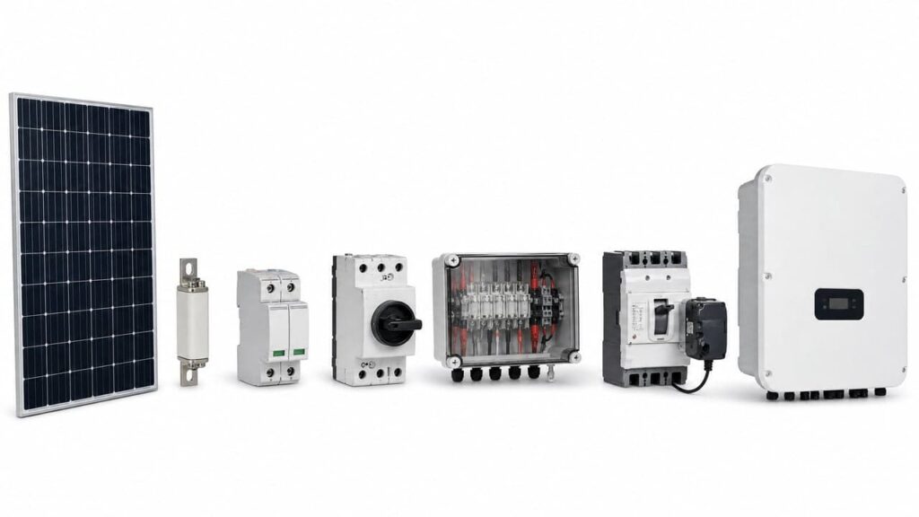
Designing motorized breakers into this stack means accounting for coordination — ensuring that when the motor operator opens a breaker, the upstream fuses and DC SPDs are still correctly rated, the Disjoncteur DC is properly coordinated, and that the isolation points remain compliant with maintenance safety standards. Internally linking related product pages — DC SPD, PV combiner box, DC fuses, and the broader solar PV electrical protection overview — helps engineers and buyers navigate the full solution rather than sourcing components piecemeal.
For teams evaluating an upgrade, the decision often comes down to a feature-by-feature comparison:
| Fonctionnalité | Traditional Breaker | Motorized Breaker |
|---|---|---|
| Contrôle à distance | Non disponible | Standard |
| Automation | Manual only | PLC/SCADA integrated |
| Status feedback | Visual only | Electrical signal to control system |
| Maintenance | Calendar-based | Data-driven |
| Smart system integration | Aucun | Complet |
The cost premium of a motorized unit is typically recovered within the first year of operation on any mid-to-large plant through reduced labor and faster fault response alone.
Selecting the right motor operator starts with matching it to the breaker and the application. To get an accurate specification and quotation, provide the following:
| Information Needed | Pourquoi c'est important |
|---|---|
| Breaker model / frame size | Ensures mechanical compatibility with the motor operator |
| Rated voltage (AC/DC) | Confirms the breaker suits the application |
| Courant nominal | Determines the correct breaker specification |
| Control voltage (e.g. 24V DC, 230V AC) | Selects the correct motor operator variant |
| Application (combiner, inverter, grid, BESS) | Allows solution-level design support |
| Quantité | Enables bulk pricing and delivery planning |
Supplying these details up front prevents the most common procurement errors — mismatched motor operators, wrong control voltages, and incompatible mounting — and shortens lead time substantially.
Remote control is powerful, but it is not the same as automatic reclosing. A motorized breaker executes a command; it does not decide whether closing is safe. Before issuing a close command after a trip, operators should verify:
| Vérifier | Objectif |
|---|---|
| Fault analysis | Confirm the fault has cleared; avoid closing into a live fault |
| Equipment inspection | Ensure cables, breakers, and connections are not damaged |
| Protection status | Verify protection devices are healthy and reset |
| Interlocking and authorization | Confirm the close is permitted by system interlocks and authorized personnel |
The discipline here matters because closing a breaker remotely into a fault can cause far more damage than the original event. Motorized operation removes the travel time; it does not remove the engineering judgment — particularly when operations must comply with IEC 60947-2 circuit breaker safety requirements.
1. What is a motorized circuit breaker? A circuit breaker fitted with a motorized operating mechanism that allows it to be opened and closed remotely via an electrical control signal, while retaining its full protection function.
2. How does a motor operator work? A control signal activates a motor, which through gears and linkages drives the breaker’s operating shaft to the open or closed position. Auxiliary contacts then report the new status back to the control system.
3. Can circuit breakers be controlled remotely? Yes, when equipped with a motor operator (for open/close) or a shunt trip release (for remote tripping only). Full remote open and close requires a motorized operating mechanism.
4. Are motorized breakers suitable for solar farms? They are ideal for solar farms, where equipment is dispersed and site visits are costly. Remote switching improves fault response time and supports unattended operation.
5. What control voltage does a motor operator need? Common control voltages are 24V DC, 48V DC, 110V DC, 230V AC, and 400V AC. The correct option depends on the site’s auxiliary power supply and control system design.
6. Can motorized breakers connect with SCADA systems? Yes. Through auxiliary contacts and PLC integration, breaker status and operation commands integrate directly into SCADA and EMS platforms.
7. What is the difference between a motor operator and a shunt trip? A shunt trip can only open (trip) a breaker remotely. A motor operator can both open and close remotely, making it suitable for full remote switching operation.
8. Where are motorized breakers installed in PV systems? On the DC side: combiner boxes, DC distribution cabinets, and battery circuits. On the AC side: inverter output cabinets, grid connection cabinets, and AC distribution panels.
9. How do motorized breakers improve solar maintenance? By reducing site visits, speeding up fault isolation, enabling data-driven maintenance planning, and supporting unattended plant operation.
10. What information is needed to select a motor operator? Breaker model, rated voltage and current, control voltage, application, and quantity — enough to confirm compatibility and provide an accurate quotation.
The motorized circuit breaker for solar PV is not an accessory. It is the device that makes remote operation and intelligent O&M possible across the DC and AC sides of a modern solar plant — from combiner boxes to grid connection cabinets and battery storage systems. By replacing slow, costly manual switching with seconds-fast remote control and closed-loop status feedback, it lowers O&M cost, raises availability, and turns a dispersed array of breakers into a coordinated, software-driven system.
KUANGYA supplies motorized operating mechanisms and complete PV distribution solutions, with OEM customization and bulk supply for solar projects of any scale. To get the right motor operator for your breakers, contact KUANGYA with:
Share these details and our engineering team will confirm compatibility and deliver a specification and quotation tailored to your project.

