WengYang Industriegebiet Yueqing Wenzhou 325000
Arbeitszeiten
Montag bis Freitag: 7AM - 7PM
Am Wochenende: 10AM - 5PM
WengYang Industriegebiet Yueqing Wenzhou 325000
Arbeitszeiten
Montag bis Freitag: 7AM - 7PM
Am Wochenende: 10AM - 5PM

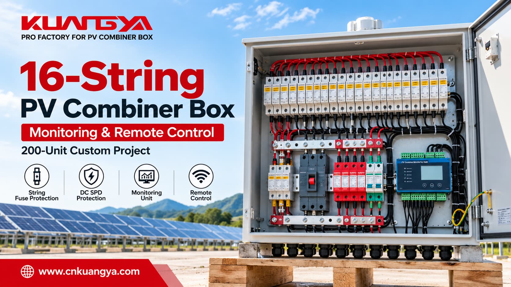
Eine große PV-Kombinationsbox leistet weit mehr, als lediglich mehrere Solaranlagenstränge in einem Gehäuse zusammenzuführen.
Bei gewerblichen und großflächigen Photovoltaikprojekten besteht die Herausforderung nicht nur darin, DC-Stromkreise zu kombinieren. Das System kann auch individuellen Stringschutz, Überspannungsschutz, zentrale Schaltung, Überwachung des Betriebszustands, Kommunikation und Fernsteuerungsfunktionen erfordern.
Genau das wurde mit dieser kundenspezifischen 16-String-PV-Kombinationsbox für dieses Projekt entwickelt.
Wir haben kürzlich hergestellt 200 kundenspezifische PV-Kombinationskästen, jeweils konfiguriert mit 16 PV-String-Eingängen und 1 DC-Ausgang, zusammen mit PV-String-Sicherungsschutz, DC-Überspannungsschutz, einer PV-Kombinations-Überwachungseinheit und projektspezifischer Fernsteuerungsfunktionalität.
Diese Anleitung erklärt, was ein PV-Kombinationskasten mit 16 Eingängen und 1 Ausgang leistet, was sich darin befindet, wie Überwachung und Fernsteuerung integriert werden können und was Ingenieure und Käufer vor der Bestellung einer kundenspezifischen Lösung spezifizieren sollten.
A 16-String-PV-Kombinationsbox empfängt Gleichstrom von 16 Photovoltaik-Strings und fasst diese zu einem ausgehenden Gleichstromkreis zusammen, bevor die Leistung zu einem Wechselrichter oder anderen nachgeschalteten Gleichstromgeräten weitergeleitet wird.
Je nach Projektentwurf kann ein PV-Kombinationskasten integrieren:
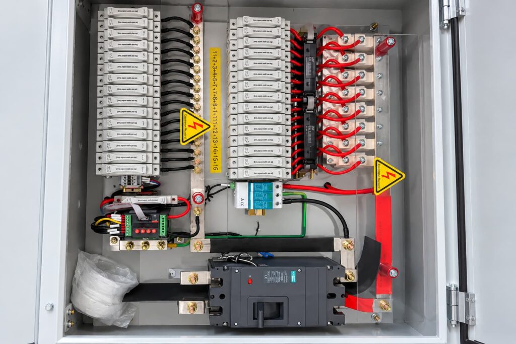
In diesem 200 Einheiten umfassenden kundenspezifischen Projekt wurden die Kombinationskästen um eine 16-Eingangs- / 1-Ausgangs-Architektur aufgebaut mit integrierter Überwachungs- und Fernsteuerungsfunktionalität.
PV-Anlagendesign muss auf Systemebene betrachtet werden. IEC 62548-1:2023+AMD1:2025 behandelt die Anforderungen an das Design von Photovoltaik-Anlagen, einschließlich DC-Verkabelung, elektrischen Schutzvorrichtungen, Schalten und Erdungsmaßnahmen.
Eine Photovoltaik-Installation kann viele einzelne PV-Strings enthalten.
Jeder String erzeugt unabhängig voneinander Gleichstrom. Anstatt jeden String separat über eine lange Distanz zu einem zentralen Wechselrichter zu führen, kann eine Kombinationsbox mehrere String-Schaltungen an einem zentralen Punkt zusammenführen.
Eine typische 16-String-PV-Kombinationsbox folgt dieser grundlegenden Architektur:
PV-String 1
PV-String 2
PV-String 3
…
PV-String 16
↓
Einzelner Stringschutz
↓
Positive und negative DC-Sammelschienen
↓
Haupt-DC-Ausgangsschaltung / -schutz
↓
1 kombinierter DC-Ausgang
↓
Solarwechselrichter
Der DC-SPD ist als paralleler Überspannungsschutz-Zweig angeschlossen gemäß der erforderlichen Schutztopologie, anstatt in Reihe mit dem normalen PV-Leistungspfad platziert zu werden.
Gleichzeitig können Sensoren und Signalstromkreise Betriebsinformationen an die Überwachungseinheit senden.
Der Begriff 16 Eingänge 1 Ausgang, oder 16 Ein 1 Aus, bedeutet daher, dass sechzehn separate PV-String-Stromkreise in die Sammelbox eintreten und zu einem ausgehenden DC-Stromkreis zusammengefasst werden.
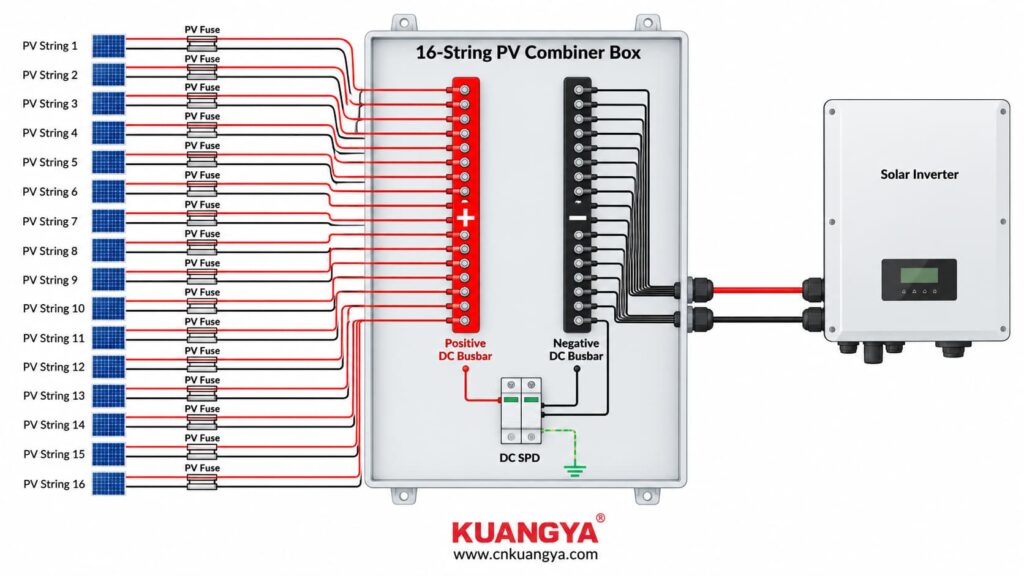
Diese Architektur zentralisiert die Zusammenfassung, den Schutz, die Überwachung und die Schaltfunktionen innerhalb eines Gehäuses.
Für ein kleineres Beispiel desselben Sammelprinzips siehe KUANGYA’s 3-String 1-Ausgang PV-Sammelbox, das PV-String-Schutz, DC-Überspannungsschutz und DC-Schalten integriert.
Die genaue interne Konfiguration variiert von Projekt zu Projekt.
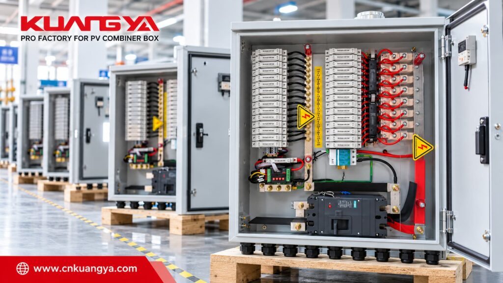
In diesem kundenspezifischen 200-Einheiten-Projekt integriert der Schrank mehrere funktionale Abschnitte, einschließlich PV-String-Sicherungsschutz, DC-Sammelschienen, Überspannungsschutz, Überwachungskomponenten und einer Haupt-DC-Schalteinrichtung.
Die eingehenden PV-Strings werden gemäß dem Projektdesign mit speziellen PV-Sicherungshaltern und gPV-Sicherungs-Links geschützt.
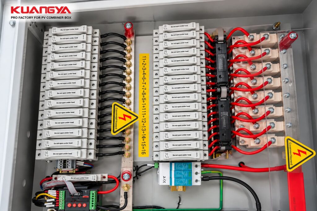
Der Zweck des Überstromschutzes auf String-Ebene ist die Unterbrechung von übermäßigem Rückstrom oder Fehlerstrom, wo die PV-Array-Konfiguration einen solchen Schutz erfordert.
PV-Sicherungen sind speziell für photovoltaische Gleichstromkreise konzipiert.
IEC 60269-6 enthält zusätzliche Anforderungen für Sicherungen, die zum Schutz von Photovoltaik-Strings und Photovoltaik-Anlagen verwendet werden.
Bei der Auswahl einer PV-Sicherung sollten Ingenieure Parameter wie die folgenden berücksichtigen:
Eine detailliertere Erklärung zur Auswahl von PV-Sicherungen und Anwendungen in Kombinationskästen finden Sie unter DC-Sicherungsanwendungen in Solar-Kombinationskästen.
Nachdem die einzelnen String-Schaltungen die erforderlichen Schutzkomponenten durchlaufen haben, werden sie auf den DC-Sammelschienen zusammengeführt.
Die Sammelschienen bilden den Hauptelektrischen Sammelpunkt im Gehäuse.
Anstelle von sechzehn unabhängigen Ausgangsschaltungen, die weiter nach unten führen, werden die String-Ströme zu einer gemeinsamen DC-Ausgangsschaltung kombiniert.
Bei einem PV-Kombinationskasten für höhere Ströme müssen Faktoren wie die folgenden berücksichtigt werden:
Die Sammelschiene ist daher nicht nur ein metallisches Verbindungsband. Sie ist ein wichtiges stromführendes Bauteil der kompletten Kombinationsbox-Baugruppe.
PV-Anlagen können transienten Überspannungen ausgesetzt sein, die durch blitzbedingte elektromagnetische Effekte und Schaltvorgänge verursacht werden.
Eine richtig ausgewählte DC-Überspannungsschutzgerät, oder DC SPD, kann daher Teil des Überspannungsschutzkonzepts der PV-Anlage sein.
Ein wichtiger Punkt ist, dass die SPD nicht in Reihe mit dem normalen PV-Betriebsstrom installiert.
Stattdessen wird es gemäß der erforderlichen Schutztopologie parallel geschaltet.
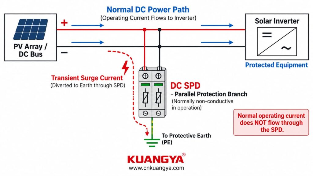
Unter normalen Betriebsbedingungen verbleibt das SPD in einem hochohmigen Zustand. Wenn eine transiente Überspannung auftritt, reagiert es, indem es einen niederohmigeren Pfad für den Stoßstrom bereitstellt und die an der geschützten Ausrüstung anliegende transiente Spannung begrenzt.
IEC 61643-31 gilt für SPDs, die für den Überspannungsschutz auf der DC-Seite von Photovoltaikanlagen mit einer Nennspannung von bis zu 1500 V DC bestimmt sind.
Eine detailliertere Erklärung des Funktionsprinzips finden Sie unter Funktionsweise eines DC-Überspannungsschutzgeräts.
Nach der Zusammenführung der Strangströme erfordert der ausgehende DC-Stromkreis eine geeignete Schaltfunktion und, je nach Ausführung, Überstromschutzeinrichtungen.
In dieser Art von PV-Kombinationsbox ist auf der Ausgangsseite eine Haupt-DC-Schalteinrichtung installiert.
Depending on the selected device and project design, its functions may include:
The selected device must be suitable for the actual DC voltage, output current, breaking requirements, and switching duty of the system.
An AC-rated device should never be assumed to be suitable for the same voltage and current in a DC application.
One of the key differences between a basic PV combiner box and the customized units in this project is the inclusion of a PV combiner monitoring unit.
Depending on the manufacturer and system architecture, similar equipment may also be described as a PV string monitoring unit oder PV combiner monitoring device.
The monitoring unit acts as a field-level data acquisition point.
Instead of seeing only the combined output of all sixteen PV strings, the plant monitoring system can receive more detailed operating information from the combiner box.
Depending on the monitoring hardware, sensors, auxiliary contacts, and project configuration, available data may include:
However, these functions are not universal.
For example, SPD status can only be transmitted when the SPD provides the required remote-signaling contact and that contact is connected to the monitoring system.
Similarly, breaker status requires suitable auxiliary contacts or other sensing arrangements.
The exact monitored parameters should therefore be confirmed during the project-design stage.
It is useful to separate a monitored combiner box into two paths.
PV Strings → String Protection → DC Busbars → Main DC Switching Device → Inverter
Sensors / Auxiliary Contacts → PV Combiner Monitoring Unit → Communication Network → Plant Monitoring System
These two paths perform different functions.
Die power path carries electrical energy.
Die monitoring path carries operating information.
The monitoring system can therefore provide visibility into individual input circuits without becoming part of the main PV current path.
For a broader overview of the protection and monitoring architecture inside a PV combiner box, see Solar PV Combiner Box Konfigurationsdiagramm.
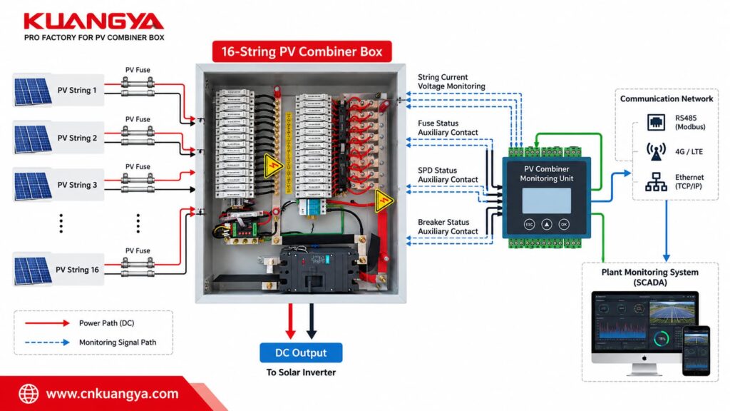
A monitored PV combiner box can be configured for different levels of data collection.
The actual functions depend on the hardware and project specification.
Current sensors can be used to measure the operating current of individual PV strings.
Comparing string currents can help identify unusual differences between otherwise similar PV strings.
Where voltage sensing is included, the monitoring system can collect DC voltage information from the combiner box.
If the installed SPD is equipped with a compatible remote-signaling contact, its status can be transmitted to the monitoring system.
Fuse-operation monitoring may be possible when dedicated detection hardware or suitable signal circuits are included.
Auxiliary contacts can be used to report the position or status of the main switching device.
Additional digital signals or communication-status information can also be collected when required by the project.
Der wichtige Punkt ist:
The monitoring capability depends on the complete sensing and communication configuration, not simply on the presence of a monitoring unit.
Consider a 16-string PV array in which fifteen strings are operating normally while one string develops an abnormal operating condition.
If operators can see only the total combined output, the effect of one abnormal string may be less obvious than a complete system failure.
String-level monitoring provides more detailed information closer to the PV array.
Abnormal string-current data can help maintenance personnel narrow down the area that requires inspection.
Instead of beginning every inspection by manually checking every string, technicians can use available monitoring data as part of the troubleshooting process.
Operators can compare individual string performance instead of relying entirely on a single combined-output value.
As the number of PV strings and combiner boxes increases, centralized monitoring can provide more useful operating visibility across the installation.
Monitoring does not automatically diagnose every fault, but it provides engineers with additional information for analysis and maintenance.
Monitoring and remote control are related, but they are not the same function.
A simple way to understand the difference is:
Monitoring tells the system what is happening.
Remote control allows a permitted action to be initiated through the control system.
A basic combiner box may provide:
Combine + Protect
A monitored combiner box can provide:
Combine + Protect + Monitor
A project with remote-control functionality can add:
Combine + Protect + Monitor + Control
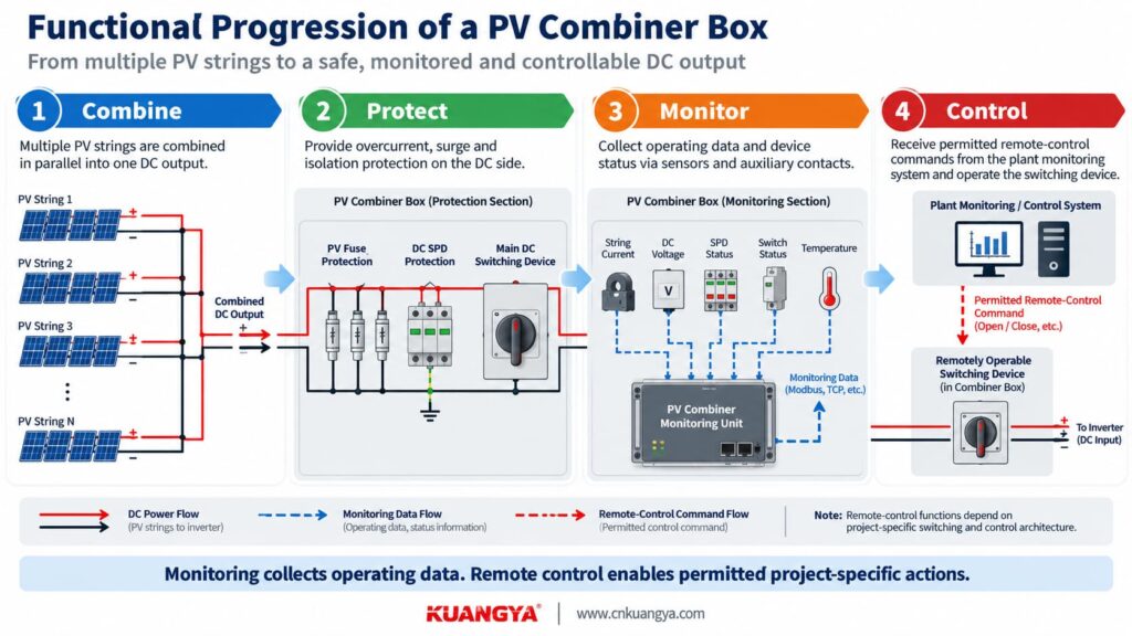
This can be useful in larger PV installations where electrical equipment is distributed across a wide site.
A technician operates or isolates the relevant switching equipment directly at the combiner-box location.
Where the electrical equipment and control architecture have been specifically designed for it, selected commands can be transmitted through the plant monitoring or control system.
The actual remote-control functions depend on factors such as:
For this reason, “remote control” should not be treated as one universal function.
The required control actions should be defined clearly before the combiner box is designed and manufactured.
Remote-control capability also does not replace the safe isolation and lockout procedures required when personnel carry out electrical maintenance.
Diese Unterscheidung ist wichtig.
A monitoring system does not replace electrical protection.
Zum Beispiel:
Monitoring provides information.
Protection devices perform protective electrical functions.
A properly designed PV combiner box integrates these functions while keeping their roles clearly separated.
This project involved 200 kundenspezifische PV-Kombinationskästen manufactured for a photovoltaic installation.
The main project configuration included:
| Project Item | Konfiguration |
|---|---|
| Menge | 200 units |
| PV Inputs | 16 Saiten |
| DC Outputs | 1 |
| String-Schutz | Individual PV fuse protection |
| Überspannungsschutz | DC SPD |
| DC Combining | Positive and negative busbars |
| Überwachung | PV combiner monitoring unit |
| Kontrolle | Project-specific remote-control functionality |
| Internal Design | Customized wiring and component layout |
The project was not simply a matter of installing more components into a larger enclosure.
The internal layout had to be designed around:
This is an important point when purchasing a customized PV combiner box:
Enclosure size is only one part of the design. The electrical architecture inside the enclosure matters much more.
A simplified power architecture can be represented as follows:
PV String 1  ─ Fuse ─┐
PV String 2  ─ Fuse ─┤
PV String 3  ─ Fuse ─┤
PV String 4  ─ Fuse ─┤
PV String 5  ─ Fuse ─┤
PV String 6  ─ Fuse ─┤
PV String 7  ─ Fuse ─┤
PV String 8  ─ Fuse ─┤
PV String 9  ─ Fuse ─┤
PV String 10 ─ Fuse ─┤
PV String 11 ─ Fuse ─┤
PV String 12 ─ Fuse ─┤
PV String 13 ─ Fuse ─┤
PV String 14 ─ Fuse ─┤
PV String 15 ─ Fuse ─┤
PV String 16 ─ Fuse ─┘
                    │
               DC Busbars
                    │
         Main DC Switching Device
                    │
              1 DC Output
                    │
                Inverter
The surge-protection circuit is connected as a parallel branch from the DC circuit according to the required SPD topology.
The monitoring system is also separate from the main power path:
String Sensors / Auxiliary Contacts
                    │
                    ↓
        PV Combiner Monitoring Unit
                    │
                    ↓
           Communication Network
                    │
                    ↓
        Plant Monitoring System
This means that the combiner box can combine the electrical power from multiple strings while still retaining operating information from individual circuits.
As PV systems become larger, the number of DC circuits that must be protected, inspected, and maintained also increases.
A small installation containing only a few strings is relatively simple to inspect.
A larger commercial or utility PV project may contain many strings distributed across multiple combiner boxes.
Centralized combining and monitoring can help organize these circuits more effectively.
A combiner box provides a centralized location for functions such as:
This can make the DC architecture easier to document, inspect, and maintain.
When one PV string behaves differently from comparable strings, individual current data can help maintenance teams narrow down the circuit that requires further inspection.
Where equipment is distributed across a large site, remote monitoring and project-specific remote-control functions can reduce the need for some routine checks or operational actions to be performed locally.
Safety-critical maintenance activities still require the applicable local isolation procedures.
Nein.
The correct 16-String-PV-Kombinationsbox configuration depends on the complete PV system.
A separate large combiner box may not be necessary where:
The number of combiner-box inputs should therefore be selected according to the array architecture, inverter configuration, protection requirements, and project design rather than simply choosing the largest available model.
For a broader guide to the role of a combiner box within the PV protection system, see Solar-Anschlusskasten: Schutz- und Wartungsanleitung.
Whether an SPD is required, and how it should be configured, depends on the installation’s surge-protection assessment, equipment arrangement, applicable standards, and project requirements.
When a DC SPD is specified, several parameters need to be considered:
It is therefore not sufficient simply to specify:
“Add one SPD.”
The SPD must be selected as part of the complete PV surge-protection concept.
For more information on interpreting key PV SPD parameters, see Erläuterung der Spezifikationen für DC-Überspannungsschutzgeräte (SPD): Klasse II, Ucpv, In, Imax, Up & Iscpv.
| Merkmal | Basic PV Combiner Box | Monitored PV Combiner Box |
|---|---|---|
| Zusammenführung mehrerer PV-Strings | Ja | Ja |
| String fuse protection | Project dependent | Project dependent |
| DC SPD | Project dependent | Project dependent |
| Main DC switching | Project dependent | Project dependent |
| Individual string monitoring | Usually not included | Can be included |
| Kommunikation | Usually not included | Can be included |
| Remote status signals | Usually not included | Can be included |
| Remote-control capability | Not standard | Can be configured |
| Centralized operating visibility | Begrenzt | Greater |
| Integration with plant monitoring system | Grundlegend | Mehr Flexibilität |
A monitored 16-String-PV-Kombinationsbox is not automatically the right choice simply because it contains more electronics.
The additional monitoring and control functions are useful when the project actually requires them.
A request such as:
“Please quote a 16-string PV combiner box.”
is usually not enough for an accurate configuration.
A useful RFQ should provide the following information.
Zum Beispiel:
16 inputs / 1 output
This determines the basic combiner-box architecture.
Provide the maximum DC voltage of the PV array, taking the project design conditions into account.
Common PV system classes include:
All relevant components must be properly rated for the actual maximum voltage of the system.
Provide at least:
These parameters are important for electrical-protection design.
Provide or confirm:
PV string fuse selection should be based on the actual PV array design rather than copied from another project.
Provide or confirm:
The combined output current affects the selection of:
Specify:
If remote operation is required, this should be stated before the electrical design is finalized.
Instead of simply saying:
“We need monitoring.”
specify what information is actually required.
Zum Beispiel:
Specify the communication interface and protocol required by the plant monitoring system.
The exact communication requirements should be confirmed before production.
Specify exactly what equipment or function needs to be controlled remotely.
Depending on the project design, this may relate to a designated switching or control device.
Der Begriff “remote control” alone is not sufficiently specific for engineering design.
Provide information such as:
Provide:
These details can significantly affect the final enclosure size and internal component arrangement.
Before requesting a quotation, prepare the following information.
Providing this information at the RFQ stage reduces unnecessary back-and-forth communication and helps prevent incompatible components from being selected later.
Ja.
The number of PV strings is only one part of the design.
A customized PV combiner box can be configured according to:
For example, one project may require a simple 3-input 1-output PV combiner box, while another may require a 16-input 1-output unit with monitoring and remote control.
The correct solution depends on the PV system—not simply on the number of inputs printed on the enclosure.
It means that sixteen separate photovoltaic string circuits enter the combiner box and are combined into one outgoing DC circuit.
The individual strings can still have separate overcurrent protection and monitoring before they are combined.
A PV combiner monitoring unit is a device used to collect and communicate operating information from the combiner box.
Depending on the connected sensors, signal inputs, and auxiliary contacts, it may collect individual string-current values, DC voltage, device-status signals, alarms, or other project-specific information.
Yes, if suitable individual string-current sensing channels and a compatible monitoring unit are included in the design.
A conventional combiner box without this hardware cannot provide string-level current monitoring by itself.
It can, provided that the system includes an appropriate fuse-status detection method or sensing circuit.
The presence of a monitoring unit alone does not automatically provide fuse-status detection.
Yes, if the SPD has a compatible remote-signaling contact and that signal is connected to the monitoring system.
Nein.
Monitoring collects information about operating conditions.
Protection devices such as fuses, SPDs, and circuit breakers perform electrical protective functions.
The two functions can work together, but they should not be confused.
Yes, when the relevant switching or control device, electrical architecture, interlocking, and communication system are specifically designed for remote operation.
The exact remote-control functions vary from project to project.
Nicht unbedingt.
Whether string overcurrent protection is required depends on factors such as the PV module characteristics, number of parallel strings, possible reverse current, conductor sizing, and applicable project-design requirements.
The protection arrangement should therefore be determined from the actual PV system.
Many PV installations use DC SPDs as part of their transient-overvoltage protection strategy, but the actual requirement and configuration depend on the installation.
The SPD voltage rating, classification, installation position, connection arrangement, cable routing, and overall lightning and surge-protection concept should all be considered.
At minimum, provide:
The more complete the project information, the more accurately the PV combiner box can be configured.
A 16-String-PV-Kombinationsbox is more than a junction point for sixteen PV circuits.
When monitoring, communication, and remote-control functions are integrated, the combiner box can also become an important field-level component within a larger solar PV monitoring and control architecture.
In this customized project, 200 units were manufactured around a 16-input 1-output configuration with PV string fuse protection, DC surge protection, PV combiner monitoring, and project-specific remote-control functionality.
The most important point is that these components should not be selected independently.
The PV fuse, DC SPD, busbars, main switching device, monitoring system, communication architecture, wiring, and enclosure all need to match the same PV project requirements.
If you are planning a customized PV combiner box, prepare the following information first:
String quantity + system voltage + module Voc/Isc + output current + protection requirements + monitoring requirements + communication requirements + remote-control requirements.
This allows the complete configuration to be reviewed before quotation and production.
Whether your project requires a simple multi-string combiner box or a 16-input 1-output PV combiner box with monitoring and remote control, KUANGYA can configure the internal protection, wiring, monitoring, and control architecture according to your project requirements.
Send us your PV system specifications to discuss a suitable configuration.

