WengYang Industriegebiet Yueqing Wenzhou 325000
Arbeitszeiten
Montag bis Freitag: 7AM - 7PM
Am Wochenende: 10AM - 5PM

WengYang Industriegebiet Yueqing Wenzhou 325000
Arbeitszeiten
Montag bis Freitag: 7AM - 7PM
Am Wochenende: 10AM - 5PM

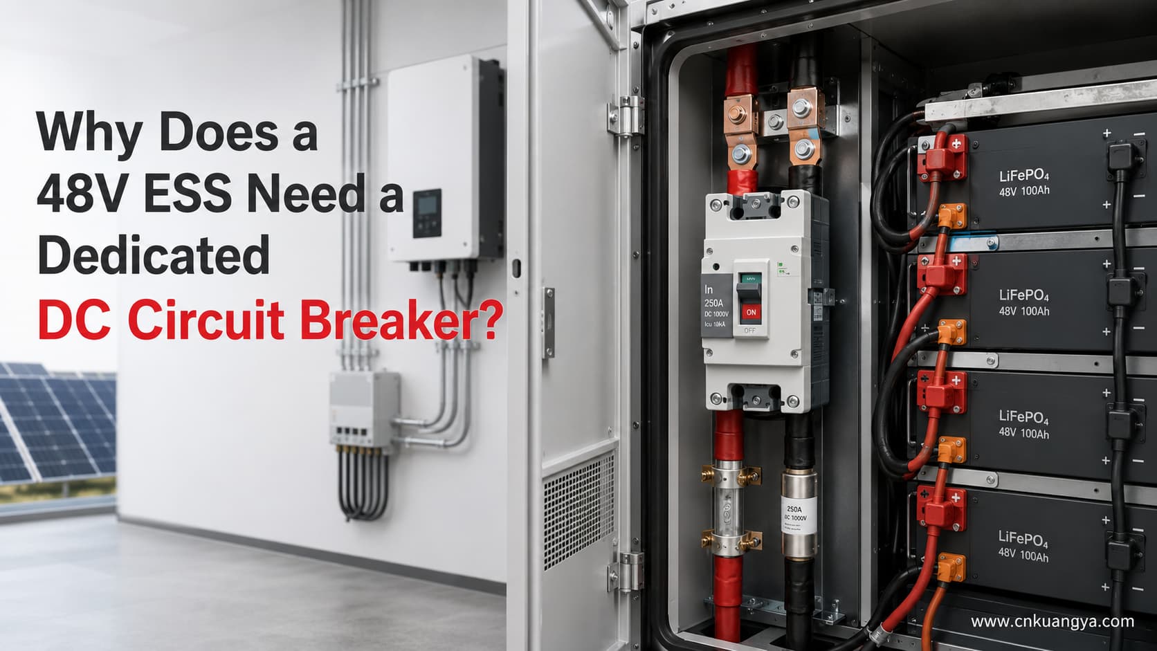
Ein 48V-Energiespeichersystem wird üblicherweise als Niederspannungssystem bezeichnet. Niederspannung bedeutet jedoch nicht ein geringes elektrisches Risiko.
Wenn eine 48V-Batteriebank einen Hochleistungswechselrichter speist, kann der Strom auf der Batterieseite leicht 100A, 200A oder sogar 250A überschreiten. Dieser Strom fließt durch Batteriekabel, Sammelschienen, Klemmen, Schütze, Sicherungen, Leistungsschalter und Wechselrichter-Eingangsleiter.
Wenn eine Überlast, ein Kurzschluss, eine lose Verbindung, ein Isolationsfehler oder ein Fehler im Batteriezweig auftritt, können die resultierende Wärme und Fehlerenergie Leiter und Ausrüstung beschädigen.
Aus diesem Grund wird ein korrekt ausgewählter 48V-Gleichstrom-Leistungsschalter häufig als Teil des batterieseitigen Schutzsystems installiert.
Der Schutzschalter darf jedoch nicht allein auf Basis der Wechselrichterleistung ausgewählt werden. Die vollständige Auslegung sollte Folgendes berücksichtigen:
Für eine ausführlichere Erläuterung zu Spannung, Stromstärke, Ausschaltvermögen, Polkonfiguration und Koordination von ESS-Leistungsschaltern lesen Sie unseren vollständigen Auswahlleitfaden für DC-Leistungsschalter für ESS.
Ein 48V-ESS benötigt ein dediziertes DC-Überstromschutzsystem, da eine Niederspannungsbatterie dennoch sehr hohe Ströme liefern kann.
Eine richtig ausgewählte 48V-Gleichstrom-Leistungsschalter kann bereitstellen:
Das BMS überwacht normalerweise Batteriespannung, Zellspannung, Strom, Temperatur und Betriebsgrenzen. Abhängig von der Systemarchitektur kann es den Wechselrichter, das Ladegerät, das Schütz oder eine externe Schaltvorrichtung anweisen, den Stromfluss zu unterbrechen.
Das macht das BMS nicht automatisch zu einem Ersatz für eine dedizierte Überstromschutzeinrichtung.
BMS, Schütz, Sicherung und DC-Leistungsschalter (MCCB) erfüllen unterschiedliche Funktionen.
| Gerät | Hauptfunktion | Überwacht automatisch Batteriezellen? | Kann Fehlerströme unterbrechen? | Rücksetzbar? | Manuelle Trennfunktion |
|---|---|---|---|---|---|
| BMS | Überwacht und steuert die Betriebsbedingungen der Batterie | Ja | Üblicherweise über ein weiteres Schaltgerät | Ja | Normalerweise nein |
| Schütz | Verbindet oder trennt die Batterie elektrisch | Nein | Nur innerhalb seiner spezifizierten DC-Abschaltleistung | Ja | Wird normalerweise nicht als primärer manueller Trennschalter verwendet |
| Sicherung | Bietet einmaligen Überstrom- und Kurzschlussschutz | Nein | Ja, innerhalb seiner DC-Bemessung | Nein | Nein |
| DC-MCCB | Bietet Überlast- und Kurzschlussschutz | Nein | Ja, innerhalb des verifizierten DC-Ausschaltvermögens | Ja | Möglich, wenn für Schalt- oder Trennfunktionen ausgelegt |
| Switch-disconnector | Provides manual isolation | Nein | Not necessarily suitable for fault interruption | Ja | Ja |

Modern BMS documentation shows that the BMS may monitor cell voltage, current, and temperature and then send commands to loads, chargers, or contactors. One practical example is the Victron VE.Bus BMS NG manual, which describes cell-level monitoring and the enabling or disabling of charging and discharging according to battery conditions. Some systems use a contactor as a secondary safety device if normal BMS control functions fail. This confirms that monitoring, control, switching, and overcurrent protection are separate functions that must be coordinated.
The correct conclusion is:
These devices perform different functions and should be coordinated as part of the complete ESS protection design.
For a focused comparison of operating speed, reset capability, maintenance, and typical applications, read our DC circuit breaker vs DC fuse guide.
The basic relationship between power, voltage, and current is:
P = V × I
Daher:
I = P ÷ V
For an inverter, efficiency must also be considered. A more useful battery-side current estimate is:
I₍DC₎ = P₍AC output₎ ÷ (V₍battery₎ × η)
Wo:
For example, 95% efficiency is entered as 0.95.
This formula estimates steady-state battery current. It does not include every possible variable, such as inverter standby consumption, control-system consumption, cable losses, temporary overload, startup surge, current ripple, or manufacturer-specific operating limits.
The following calculations assume 95% inverter efficiency.
| AC output power | Battery voltage under load | Assumed efficiency | Berechnung | Estimated battery current |
|---|---|---|---|---|
| 5,000W | 48V | 95% | 5,000 ÷ (48 × 0.95) | 109.6A |
| 5,000W | 44V | 95% | 5,000 ÷ (44 × 0.95) | 119.6A |
| 5,000W | 42V | 95% | 5,000 ÷ (42 × 0.95) | 125.3A |
| 10,000W | 48V | 95% | 10,000 ÷ (48 × 0.95) | 219.3A |
| 10,000W | 44V | 95% | 10,000 ÷ (44 × 0.95) | 239.2A |
| 10,000W | 42V | 95% | 10,000 ÷ (42 × 0.95) | 250.6A |

These calculations show why the nominal “48V” label is not enough.
A 10kW inverter drawing from a battery at 48V may require approximately 219A under the stated assumptions. If the battery voltage falls to 42V, the calculated current rises to approximately 251A.
This is before adding design allowances for operating conditions, auxiliary consumption, cable losses, temporary overload, or manufacturer-specific requirements.
Therefore, a 250A battery breaker for an inverter is not automatically suitable for every 10kW, 48V system.
A battery described as “48V” does not remain at exactly 48.0V throughout charging and discharging.
The actual operating voltage depends on:
A published 51.2V LiFePO4 battery example has a nominal voltage of 51.2V, a recommended charging voltage between 56V and 56.8V, and an end-of-discharge voltage of 44.8V. This demonstrates why both maximum charging voltage and lower discharge voltage must be considered when selecting a breaker.
The breaker voltage rating must be higher than the maximum battery-system voltage that can appear across it.
The current calculation should also be checked at the lowest permitted operating voltage, because lower battery voltage produces higher current for the same power output.
Consider a published 48V inverter/charger with the following manufacturer data:
| Parameter | Published value |
|---|---|
| Model class | 48V / 5,000VA |
| Continuous real output at 25°C | 4,000W |
| Battery input voltage range | 38–66V |
| Maximum efficiency | 96% |
| Peak power | 9,000W |
| Recommended DC fuse | 200A |
| Recommended cable for 0–5m | 70mm² |
| Recommended cable for 5–10m | 120mm² |

These values are taken from the manufacturer’s MultiPlus-II and Quattro-II installation manual rather than estimated from the product name.
At 48V and 96% efficiency:
I = 4,000 ÷ (48 × 0.96)
I ≈ 86.8A
At 42V and 96% efficiency:
I = 4,000 ÷ (42 × 0.96)
I ≈ 99.2A
A buyer might see the calculated 87–99A current and immediately choose a 100A or 125A breaker.
However, the manufacturer recommends a 200A DC fuse for this particular inverter/charger.
Why is the recommendation higher than the basic continuous-current calculation?
Because the final protection requirement may need to account for:
This case demonstrates an important rule:
The power formula is a starting point, not the final breaker size.
The inverter manufacturer’s approved installation instructions, battery limits, cable capacity, and protective-device characteristics must all be reviewed.
It would also be incorrect to copy the manufacturer’s 200A fuse recommendation and automatically replace it with a 200A MCCB. A fuse and an MCCB may have different operating curves, short-circuit performance, let-through energy, and interruption characteristics.
Now consider a larger published inverter/charger.
| Parameter | Published value |
|---|---|
| Model class | 48V / 10,000VA |
| Continuous real output at 25°C | 8,000W |
| Continuous real output at 40°C | 7,000W |
| Continuous real output at 65°C | 6,000W |
| Battery input voltage range | 38–66V |
| Maximum efficiency | 95% |
| Peak power | 18,000W |
| Recommended DC fuse | 400A |
| Recommended cable for 0–5m | 2 × 50mm² per polarity |
| Recommended cable for 5–10m | 2 × 70mm² per polarity |

The same manufacturer manual publishes 8,000W as the continuous real output at 25°C, although the model is identified as 10,000VA. although the model is identified as 10,000VA. It also recommends a 400A DC fuse and two parallel 50mm² conductors per positive and negative connection for cable runs up to 5m.
At 48V and 95% efficiency:
I = 8,000 ÷ (48 × 0.95)
I ≈ 175.4A
At 42V and 95% efficiency:
I = 8,000 ÷ (42 × 0.95)
I ≈ 200.5A
A simple calculation might suggest that a 250A DC MCCB should be enough.
However, the manufacturer recommends a 400A fuse for this particular unit.
That does not mean every similar 48V inverter requires a 400A protective device. It means that the protection selection for this specific inverter must follow its tested and published installation requirements.
This real example also shows why an engineer must distinguish between:
A product marked “10kVA” is not necessarily delivering 10kW of continuous real power under every condition.
Consider two identical 51.2V, 100Ah LiFePO4 batteries connected in parallel.
The published specification for each battery includes:
| Parameter per battery | Published value |
|---|---|
| Nominal voltage | 51.2V |
| Nominal capacity | 100Ah |
| Nominal energy | 5.12kWh |
| Maximum continuous discharge current | 100A |
| Maximum pulse discharge current | 200A for 10 seconds |
| End-of-discharge voltage | 44.8V |
| Charging voltage | 56–56.8V |
The battery manufacturer also states that fuse selection should not exceed the lowest current rating among the battery, cable, and system limits.
With two identical batteries in parallel, the theoretical combined values become:
| Combined parameter | Berechnung | Ergebnis |
|---|---|---|
| Nominal capacity | 100Ah × 2 | 200Ah |
| Nominal energy | 5.12kWh × 2 | 10.24kWh |
| Maximum continuous discharge current | 100A × 2 | 200A |
| Maximum 10-second pulse current | 200A × 2 | 400A |

These totals assume that the two branches share current correctly and that the batteries, cables, terminals, fuses, and busbars are installed according to the manufacturer’s requirements.
This case creates an important protection question:
Can one 250A main breaker protect the entire battery system?
Possibly—but it cannot be confirmed from the total current alone.
A 250A main breaker might allow more than 100A to flow continuously through one battery branch if current sharing becomes unequal. Therefore, each battery branch may still need dedicated branch protection coordinated with:
A main 48V-Gleichstrom-Leistungsschalter does not automatically replace battery-branch fuses or breakers.
This is especially important in parallel battery systems because healthy battery branches may feed current into a faulted branch.
Battery cables may carry high current for long periods.
A cable can overheat if it is:
The breaker must protect the lowest-rated component in the current path.
A dropped tool, loose conductor, failed insulator, damaged lug, or installation error can create a short circuit across a battery busbar.
Lithium batteries may supply substantial fault current. However, the prospective short-circuit current cannot be determined accurately from battery Ah capacity alone.
The calculation may require:
The breaker’s verified DC breaking capacity must be equal to or greater than the prospective short-circuit current at the breaker installation point.
A fault may occur in the inverter input terminals, capacitors, internal conductors, or power electronics.
The BMS may detect abnormal current and command disconnection, but the result depends on sensors, software, communications, control power, switching equipment, and the nature of the fault.
Independent overcurrent protection provides another protection layer for the conductors between the battery and inverter.
The heating produced by electrical resistance is:
P = I²R
Wo:
Suppose a loose terminal develops a resistance of only 0.001Ω.
At 100A:
P = 100² × 0.001 = 10W
At 200A:
P = 200² × 0.001 = 40W
At 250A:
P = 250² × 0.001 = 62.5W
This heat is concentrated at a small terminal or connection point.
The example shows why a connection that appears to have very low resistance can still generate significant heat in a high-current 48V system.
A circuit breaker may not detect every high-resistance connection. Correct torque, suitable terminals, proper crimping, thermal inspection, and maintenance are still required.
If one parallel battery branch develops a short circuit, other battery branches may feed current into it.
This means that a single main breaker may not protect each branch conductor.
Branch fuses or breakers may be required close to each battery positive terminal, depending on the approved system design.
A BMS-controlled contactor is an important switching device, but it should not automatically be treated as the only fault-clearing device.
The contactor may depend on:
Published BMS designs may use a main contactor as a secondary safety system after normal charge and discharge control functions. This supports the principle of using coordinated protection layers rather than relying on one device.
Technicians need a clear method to isolate the battery before installation, maintenance, inspection, or component replacement.
A DC MCCB may provide manual switching and overcurrent protection, but only if the selected breaker is approved for the intended switching or isolation function.
If a fuse is used as the main overcurrent device, a separate DC switch-disconnector may also be required.
An AC breaker should not be assumed suitable for battery use merely because the battery voltage is only 48V.

For a broader explanation of arc interruption, voltage ratings, and application differences, read our guide to AC vs DC circuit protection.
Alternating current passes through zero during every half-cycle.
This natural zero crossing helps extinguish the electrical arc that forms when breaker contacts open.
Direct current does not naturally pass through zero during normal steady-state operation.
The breaker must create sufficient arc voltage and arc resistance to force the DC fault current to zero.
ABB’s technical guide to circuit breakers for direct current applications provides further guidance on DC interruption, earthing arrangements, pole connections, and short-circuit calculations.
ABB’s technical guidance explains that interrupting DC current is more difficult because there is no natural current zero. It also explains that multiple breaker contacts or poles may need to be connected in series for higher DC voltage and breaking performance.
IEC 60947-2:2024 applies to low-voltage circuit breakers with rated voltages up to 1,000V AC or 1,500V DC. However, this does not mean every IEC 60947-2 breaker is suitable for every DC voltage or battery application. The manufacturer’s exact DC ratings and connection diagrams must still be verified.
| Breaker parameter | Warum das wichtig ist |
|---|---|
| Rated DC operational voltage | Must exceed the maximum battery-system voltage |
| Nennstrom | Must coordinate with the load, battery, cable, and busbar |
| DC-Ausschaltvermögen | Must exceed the prospective fault current |
| Trip curve or trip settings | Must carry normal load and peaks without losing protection |
| Anzahl der Pole | May affect voltage rating and isolation arrangement |
| Pole connection diagram | Some DC ratings require poles connected in series |
| Polarität | Some DC breakers are polarity-sensitive |
| Line and load direction | Some products require a specified current direction |
| Bidirectional rating | Required when charge and discharge current flow through the same path |
| Isolation rating | Required when the breaker is used as an isolating device |
| Ambient derating | High cabinet temperature may reduce usable continuous current |
| Terminal limits | Terminals must accept the required conductor size and current |
Some DC breakers use permanent magnets in their arc chambers. For these designs, polarity and current direction can affect arc movement and interruption performance. Manufacturer documentation must therefore be followed exactly.
Polarity, LINE and LOAD orientation, and bidirectional current are also covered in our guide to common DC protection wiring mistakes.
A battery-side breaker primarily protects the electrical circuit and its conductors.
Depending on its location, it may protect:
The breaker does not directly monitor individual cell voltage, cell temperature, state of charge, or cell balancing.
Those remain BMS and battery-system functions.
The correct protection concept is therefore:
The BMS protects battery operating conditions, while the DC overcurrent device protects the defined circuit and conductors within its ratings.
A 250A DC MCCB may be considered for some 48V ESS applications, but the current marked on the breaker is only one part of the selection.
For a broader explanation of DC MCCB construction, trip units, breaking capacity, and applicable standards, see our Leitfaden zur Auswahl und zu den Normen für DC-Leistungsschalter.
| Selection condition | What must be confirmed | Warum das wichtig ist |
|---|---|---|
| Battery maximum voltage | Below the breaker’s DC voltage rating | A nominal 48V battery may charge above 56V |
| Maximum continuous discharge current | Compatible with the breaker trip curve | Prevents nuisance tripping and conductor overload |
| Maximum charging current | Included in the analysis | ESS current may flow in both directions |
| Lowest battery voltage | Used in current calculation | Current rises when voltage falls |
| Temporärer Spitzenstrom | Duration and magnitude are known | The breaker must tolerate legitimate peaks |
| Kapazität der Kabel | Greater than or coordinated with breaker protection | The breaker must protect the cable |
| Busbar and terminal capacity | Suitable for continuous current | Prevents localized overheating |
| Available fault current | Below verified DC breaking capacity | Ensures safe fault interruption |
| BMS and contactor limits | Compatible with breaker and system current | Prevents one device from being overloaded |
| Polkonfiguration | Suitable for grounding and isolation design | Determines which conductors are disconnected |
| Stromrichtung | Breaker approved for bidirectional operation when required | ESS charging reverses normal current direction |
| Temperatur in der Umgebung | Manufacturer derating checked | Hot cabinets affect trip behavior |
| Manufacturer instructions | Inverter and battery requirements followed | Generic calculations do not replace approved manuals |
| System condition | Is a 250A breaker automatically suitable? | Reason |
|---|---|---|
| 5kW output, 48V battery, 95% efficiency | Nein | Calculated current is about 110A, but cable, surge, trip curve, fault current, and manufacturer requirements remain unknown |
| 10kW output, 48V battery, 95% efficiency | Nein | Calculated current is about 219A, leaving limited margin before considering operating conditions |
| 10kW output, 42V battery, 95% efficiency | Usually not for continuous full output | Calculated current is approximately 251A before additional losses |
| Two 51.2V/100Ah batteries in parallel | Nein | Combined continuous current may be 200A, but each 100A battery branch may still require separate protection |
| Inverter manufacturer specifies a 400A fuse | Nein | A 250A MCCB cannot automatically replace the specified fuse |
| Cable is rated below 250A after derating | Nein | The breaker may not protect the cable adequately |
| Prospective fault current exceeds breaker DC breaking capacity | Nein | The breaker may be unable to interrupt the fault safely |
| Breaker is AC-rated only | Nein | AC ratings do not automatically establish DC interruption performance |
| DC voltage, current, trip curve, cable, fault level, poles, temperature, and manufacturer requirements are verified | Possibly | Final approval still requires system-level engineering validation |
If the system voltage, continuous current, cable capacity, pole arrangement, fault level, and current direction have been confirmed, review the KUANGYA MCCB-250DC product specifications before requesting a project quotation.

The answer depends on what “10kW inverter” means and how the system operates.
At 48V and 95% efficiency:
10,000 ÷ (48 × 0.95) ≈ 219A
At 44V:
10,000 ÷ (44 × 0.95) ≈ 239A
At 42V:
10,000 ÷ (42 × 0.95) ≈ 251A
Therefore, a 250A breaker may already be at or below the calculated full-load current when battery voltage falls.
The design must then consider:
The correct answer cannot be obtained from “10kW” and “48V” alone.
There is no universal rule stating that every 48V ESS must use only a 1P or only a 2P breaker.
| System condition | 1P may be considered | 2P may be considered |
|---|---|---|
| One conductor is intentionally grounded | Yes, subject to approved design | Manchmal |
| Floating or ungrounded DC system | Usually not enough for full isolation | Often required |
| Both conductors must be isolated | Nein | Ja |
| Insulation monitoring is used | Depends on architecture | Commonly considered |
| Manufacturer requires positive-only protection | Possible | Follow manufacturer diagram |
| Manufacturer requires all-pole disconnection | Nein | Ja |
| Single-pole breaker has sufficient DC rating | Possible | Not automatically required |
| Required DC rating needs two poles in series | Nein | Yes, using the approved wiring diagram |

A 1P 48V-Gleichstrom-Leistungsschalter may be used when:
A 2P breaker may be required when:
Do not assume that two poles always mean one pole in the positive conductor and one in the negative conductor.
Some DC breaker ratings require poles to be connected in series in a specific arrangement. Always follow the manufacturer’s wiring diagram.
A lower system voltage does not eliminate the risk of high current.
High battery current can cause:
The BMS monitors battery conditions and controls other equipment.
The breaker or fuse protects the defined circuit against overcurrent and short-circuit conditions within its rating.
They perform different functions.
An AC breaker may only be used on DC when the manufacturer provides an approved DC voltage, breaking capacity, pole arrangement, and connection diagram.
The current depends on the actual battery voltage, inverter efficiency, continuous real power, overload capability, and operating temperature.
A generic 10kW calculation at 42V and 95% efficiency already produces approximately 251A.
A 250A label does not confirm:
Battery capacity in ampere-hours indicates stored charge.
It does not directly define:
A main breaker may protect the combined output cable but may not protect each individual battery branch.
Parallel branches may require separate protection near each battery.
An ESS can carry current in both discharge and charge directions.
The breaker and protection system must be suitable for the maximum current and fault conditions in both operating modes.
A buyer should provide the following information before requesting a quotation.
| Required information | Beispiel | Why it is needed |
|---|---|---|
| Battery chemistry | LiFePO4 | Determines voltage range and battery limits |
| Nominal battery voltage | 48V or 51.2V | Basic system classification |
| Maximum charging voltage | 56.8V | Determines minimum breaker DC voltage rating |
| Minimum operating voltage | 44.8V | Used for maximum current estimation |
| Battery capacity | 200Ah | Helps describe the bank but does not determine breaker size alone |
| Number of batteries | 2 in parallel | Identifies branch-protection requirements |
| Maximum continuous discharge current | 200A total | Used for current coordination |
| Maximum charge current | 150A | Confirms reverse current requirements |
| Peak current | 350A for 5 seconds | Used to check trip characteristics |
| Inverter or PCS model | Manufacturer and exact model | Allows manual verification |
| Continuous real output | 8,000W | Used for battery-current calculation |
| Wirkungsgrad des Wechselrichters | 95% | Improves current calculation |
| Required poles | 1P or 2P | Depends on system architecture |
| Erdungskonzept | Floating or negative grounded | Affects pole selection |
| Cable cross-section | 2 × 50mm² | Required for conductor protection |
| Leitungslänge | 3m one way | Affects voltage drop and cable sizing |
| Busbar rating | 300A | Must coordinate with the breaker |
| Available fault current | Engineering calculation or manufacturer data | Determines breaking capacity |
| Betriebstemperatur | Up to 50°C | Required for breaker derating |
| Stromrichtung | Bidirectional | Important for charging and discharging |
| Required standard | IEC 60947-2 or market-specific requirement | Supports compliance review |
| Menge | 100 pieces | Required for commercial quotation |
| Destination | Country and port | Required for shipping and certification review |
A 48V lithium battery system normally requires a coordinated overcurrent protection and disconnection design.
The final solution may use:
The exact arrangement depends on the battery, inverter, cables, fault current, and applicable installation requirements.
Nein.
The BMS primarily monitors and controls battery operating conditions. The circuit breaker or fuse protects a defined circuit against overcurrent and short-circuit conditions within its verified ratings.
Only when the manufacturer explicitly provides a suitable DC rating and approved connection method.
An AC marking alone is not enough.
Start by calculating:
I₍DC₎ = P₍AC output₎ ÷ (V₍battery minimum₎ × η)
Then verify:
Not automatically.
At 48V and 95% efficiency, the estimated current is approximately 219A.
At 42V, it rises to approximately 251A.
A 250A breaker may therefore be unsuitable for continuous full-power operation at lower battery voltage.
This depends on the grounding arrangement and equipment manufacturer’s instructions.
Many battery systems place overcurrent protection in the positive conductor, but this must not be generalized to every grounded, floating, or monitored DC system.
A 1P breaker may be suitable for an approved single-conductor disconnection architecture.
A 2P breaker may be required when both positive and negative conductors must be disconnected or when two poles are needed to achieve the breaker’s verified DC rating.
Sometimes.
A fuse may provide higher short-circuit breaking capacity, faster fault interruption, branch protection, or backup protection.
Whether both devices are required depends on the coordination study and system design.
Nein.
Battery Ah capacity does not directly specify the maximum continuous current, short-circuit current, cable size, or protective-device rating.
Nein.
An oversized breaker may fail to protect the cable, battery branch, terminal, or busbar adequately.
The breaker must be coordinated with the lowest-rated protected component.
A 48V ESS is a low-voltage but potentially very high-current electrical system.
The correct protection question is not simply:
“Is 48V dangerous?”
The more useful questions are:
A dedicated 48V-Gleichstrom-Leistungsschalter can provide valuable overload protection, short-circuit interruption, manual operation, and resettable protection.
However, the breaker is only one part of the complete system.
The safest design coordinates the battery, BMS, contactor, fuse, MCCB, cable, busbar, inverter, grounding arrangement, and fault-current level.
Before selecting a 250A or any other breaker rating, provide the complete system parameters to the breaker manufacturer or qualified system designer.
The next step is not to guess the breaker size from inverter power. It is to calculate and verify the complete battery-side protection design.