WengYang Industriegebiet Yueqing Wenzhou 325000
Arbeitszeiten
Montag bis Freitag: 7AM - 7PM
Am Wochenende: 10AM - 5PM
WengYang Industriegebiet Yueqing Wenzhou 325000
Arbeitszeiten
Montag bis Freitag: 7AM - 7PM
Am Wochenende: 10AM - 5PM
smart-solar-pv-fire-protection-system-architecture
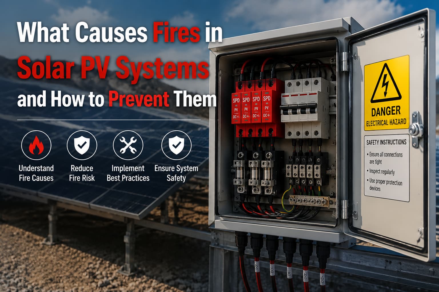
Solar PV systems are widely recognized as a safe and clean energy source. However, Solar PV Fire incidents still occur globally, particularly in utility-scale plants and commercial rooftop installations.
Most fire events are not caused by PV modules themselves, but by failures in DC-side electrical infrastructure, especially:
Dieser Artikel erläutert:
The goal is to provide a practical, engineering-based understanding of fire risk—not theoretical safety advice.
Despite improvements in PV technology, fire risk has not been eliminated. In fact, as system voltage increases from 600V to 1500V DC, the consequences of electrical faults become more severe.
A PV system is not a single device—it is a distributed electrical network exposed to environmental stress for 20–25 years.
The highest risk area is not the solar module, but the balance-of-system (BOS) components, especially the distribution box.
| Systemkomponente | Fire Contribution Level | Reason |
|---|---|---|
| PV Modules | Niedrig | Stable solid-state design |
| Wechselrichter | Mittel | Electronic protection built-in |
| DC Cables | Mittel-Hoch | Aging and insulation breakdown |
| Distribution Boxes | Sehr hoch | Connection concentration point |
| SPD Devices | High (if failed) | Surge energy exposure |
Most Solar PV Fire incidents originate at connection points, not energy generation components.
This is a critical distinction often missed in non-engineering discussions.
To understand fire prevention, we must first understand how fire actually develops inside PV systems.
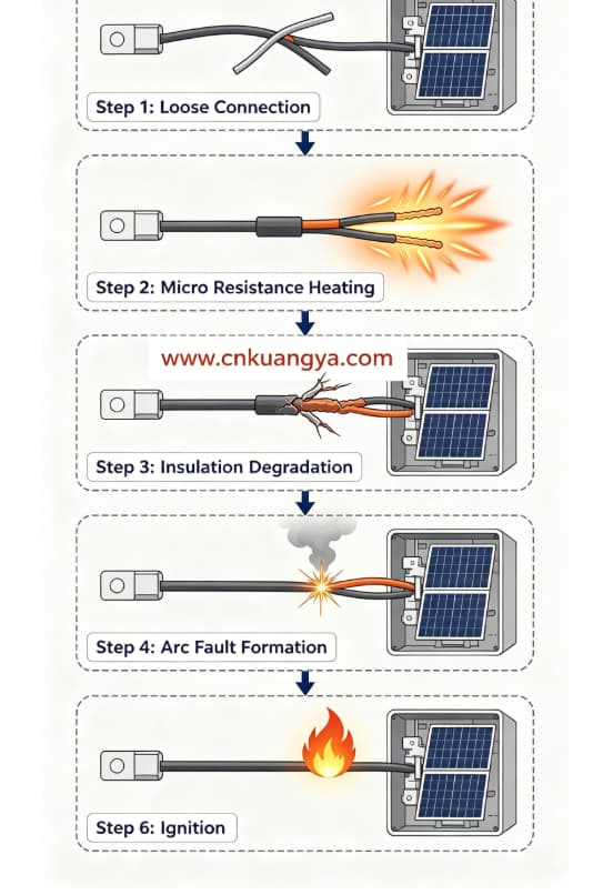
A PV fire is almost never instant. It is usually the result of a progressive electrical degradation process.
| Bühne | Elektrischer Zustand | Physikalische Auswirkung | Schwierigkeit der Erkennung |
|---|---|---|---|
| 1 | Loose connection / micro defect | Slight resistance increase | Sehr niedrig |
| 2 | Beginn der lokalen Erwärmung | Temperature rises gradually | Niedrig |
| 3 | Isolationsalterung | Materialverfärbung | Mittel |
| 4 | Teillichtbogenbildung | Intermittierende Entladung | Mittel-Hoch |
| 5 | Gleichstrom-Dauerlichtbogen | High-energy continuous discharge | High risk |
| 6 | Entzündung | Kabel- oder Gehäusebrand | Critical failure |
At early stages, the system still operates normally. This is why PV fire risk is often called a:
“Hidden degradation failure model”
Unlike mechanical failures, electrical degradation is not visible until thermal thresholds are exceeded.
Across global EPC projects, fire investigations reveal consistent patterns. While each incident differs in detail, the root causes are surprisingly similar.
| Scenario Type | Standortumgebung | Grundlegende Ursache | Ergebnis |
|---|---|---|---|
| Utility solar farm fire | Wüste (Naher Osten) | Anschlussüberhitzung im Generatoranschlusskasten | String shutdown + equipment replacement |
| Industrial rooftop fire | Manufacturing plant | Loose MC4 connector in distribution box | Roof fire propagation |
| Coastal PV plant | Humid coastal region | Korrosion im Gehäuseinneren | Fortschreitender Kurzschluss |
| High lightning zone system | Südostasien | Ausfall des Überspannungsschutzes (SPD) nach einem Stoßspannungsereignis | Inverter + BOS damage |
Studies on photovoltaic system safety indicate that DC-side electrical faults in balance-of-system components are a leading cause of fire incidents in solar installations, as documented in U.S. Department of Energy solar fire safety guidance.
Fire origin is almost always located in DC junction or distribution components, not generation equipment.
PV fire risk increases significantly depending on environment:
| Umwelt | Risikomechanismus |
|---|---|
| Wüste | Thermal expansion → loosening terminals |
| Küstennah | Salzkorrosion → Widerstandserhöhung |
| Tropisch | Moisture ingress → leakage currents |
| High UV regions | Insulation aging acceleration |
| Lightning regions | Surge overload stress |
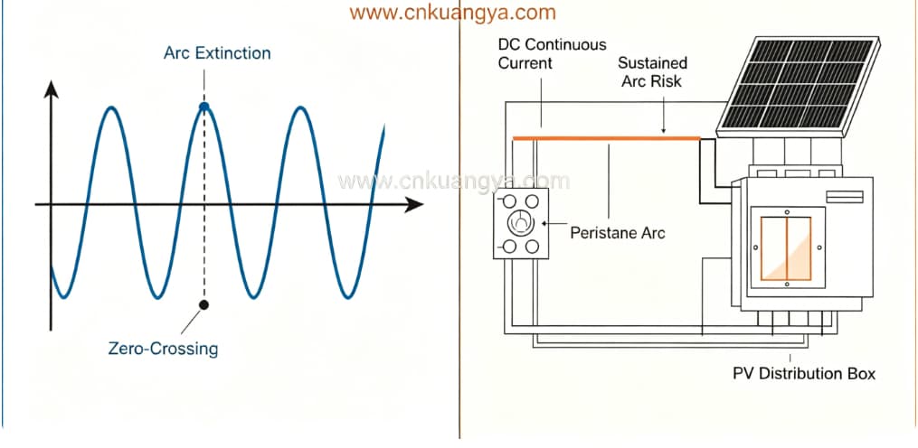
Understanding DC behavior is essential in analyzing Solar PV Fire mechanisms.
| Merkmal | AC-System | PV-DC-System |
|---|---|---|
| Stromnulldurchgang | Ja | Nein |
| Lichtbogenlöschung | Natürlich | Requires interruption |
| Fehlerunterbrechung | Einfacher | Schwierig |
| Energy behavior | Pulsed | Kontinuierlich |
| Fire propagation | Langsamer | Schneller |
In AC systems, current naturally drops to zero 50–60 times per second, helping extinguish arcs.
In DC PV systems:
This makes DC faults significantly more dangerous in fire scenarios.
PV fire incidents are rarely caused by a single issue. Instead, they result from combined stress factors.
Most PV fires are not sudden failures.
They are:
“Accumulated small defects reaching a thermal tipping point.”
One of the most critical issues in real PV operation is that early warning signs are often visible—but ignored.
| Warnsignal | Technische Bedeutung |
|---|---|
| Slight discoloration inside box | Lokale Überhitzung |
| Brandgeruch | Verschlechterung der Isolierung |
| Intermittierende Wechselrichteralarme | Lichtbogen oder Spannungsschwankungen |
| One string hotter than others | Resistance imbalance |
| Änderung der SPD-Anzeige | Surge exposure event |
In most real EPC cases:
Systems operate normally until failure suddenly becomes visible.
But in reality, degradation has already been ongoing for weeks or months.
At this stage, understanding the causes is not enough. What matters is how to prevent escalation at each stage of failure development.
In real photovoltaic system design, surge protection and overcurrent protection must be coordinated to ensure a complete DC side protection strategy for solar PV systems.
Modern Solar PV Fire prevention strategy is based on layered protection:
Each layer targets a different failure stage.
In real EPC engineering, many Solar PV Fire incidents are not caused during operation, but are already “pre-designed” at the engineering stage.
PV system design and installation safety should comply with international photovoltaic standards, especially regarding DC system protection and wiring safety requirements under IEC 62548 photovoltaic array design standard.
The PV distribution box is the central convergence point of DC strings, and its internal layout directly determines thermal behavior, electrical stability, and fault response capability.
A poorly designed box can create heat concentration zones even if all components are compliant.
| Gestaltungselement | Engineering Requirement | Fire Risk if Poorly Designed |
|---|---|---|
| Internal wiring layout | Clear separation of DC paths | Heat concentration and arcing risk |
| Schutzart des Gehäuses | IP65–IP66 outdoor protection | Durch Feuchtigkeit verursachte Kurzschlüsse |
| Material selection | Flame-retardant housing | Brandausbreitung innerhalb des Gehäuses |
| Thermisches Design | Passive/active heat dissipation | Continuous temperature rise |
| Terminal arrangement | Torque-controlled connection points | Langzeit-Widerstandserwärmung |
One of the most underestimated issues in PV design is thermal accumulation inside sealed enclosures.
Even when electrical load is within specification, lack of ventilation or poor heat dispersion can lead to:
This slow thermal accumulation often becomes the hidden trigger of Solar PV Fire incidents.
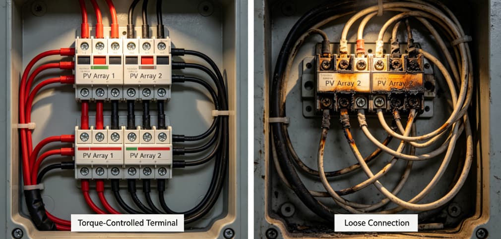
Across EPC projects worldwide, installation quality remains one of the most critical factors in fire prevention.
Even with high-quality components, improper installation can introduce permanent electrical weaknesses.
Terminals require precise torque values. However, in field installation:
Both conditions increase long-term thermal risk.
Inside distribution boxes, wiring density is often underestimated.
Poor routing leads to:
In many PV systems, grounding is treated as secondary.
However, incomplete grounding causes:
Skipping proper testing leads to:
| Installationsbereich | Common Error | Auswirkungen bei Brand |
|---|---|---|
| Terminals | Keine Drehmomentkontrolle | Progressive overheating |
| Cabling | Overcrowding | Thermische Hotspots |
| Erdung | Partial earthing | Überspannungsakkumulation |
| Prüfung | Incomplete commissioning | Hidden electrical faults |
PV systems are designed for long operational lifespans, typically 20 to 25 years. However, electrical components degrade continuously due to environmental exposure and thermal cycling.
Without proper maintenance, even a perfectly designed system will eventually develop fire risk conditions.
| Intervall | Inspection Type | Zweck |
|---|---|---|
| Monatlich | Visuelle Kontrolle | Verfärbungen oder Gerüche erkennen |
| Vierteljährlich | Thermografie-Scan | Identifizierung von Hotspot-Entwicklungen |
| Halbjährlich | Torque verification | Prevent terminal loosening |
| Jährlich | SPD inspection | Sicherstellung der Integrität des Überspannungsschutzes |
| 3–5 Jahre | Überprüfung des Komponentenaustauschs | Avoid aging failure accumulation |
Infrarot-Thermografie ist eines der effektivsten Werkzeuge zur Solar PV Fire prevention strategy.
Sie ermöglicht die Erkennung von:
Most importantly, it identifies problems bevor physische Schäden auftreten.
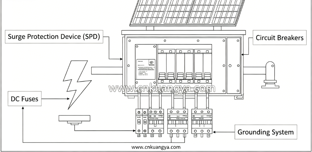
Surge Protection Devices (SPDs) are critical in PV systems, especially in lightning-prone regions.
A surge event can introduce extremely high transient voltage into DC circuits. Without proper suppression, this energy can damage insulation inside distribution boxes and trigger arc formation.
| Funktion | Fire Prevention Role |
|---|---|
| Spannungsbegrenzung | Prevent insulation breakdown |
| Ableitung von Überspannungen | Redirect lightning energy safely |
| Thermal stress reduction | Reduce component overheating |
| Systemstabilisierung | Prevent transient arc initiation |
SPDs do not fail instantly. Instead, they degrade gradually after multiple surge events.
If not monitored or replaced, they become a silent risk factor inside the system.
This is why SPD coordination is not optional—it is a core part of Distribution Box Fire Protection engineering design.
Surge Protection Devices play a critical role in reducing lightning-induced failure risks in photovoltaic systems. Proper coordination of DC surge protection devices for solar PV systems is essential to prevent insulation breakdown and fire ignition inside distribution boxes.
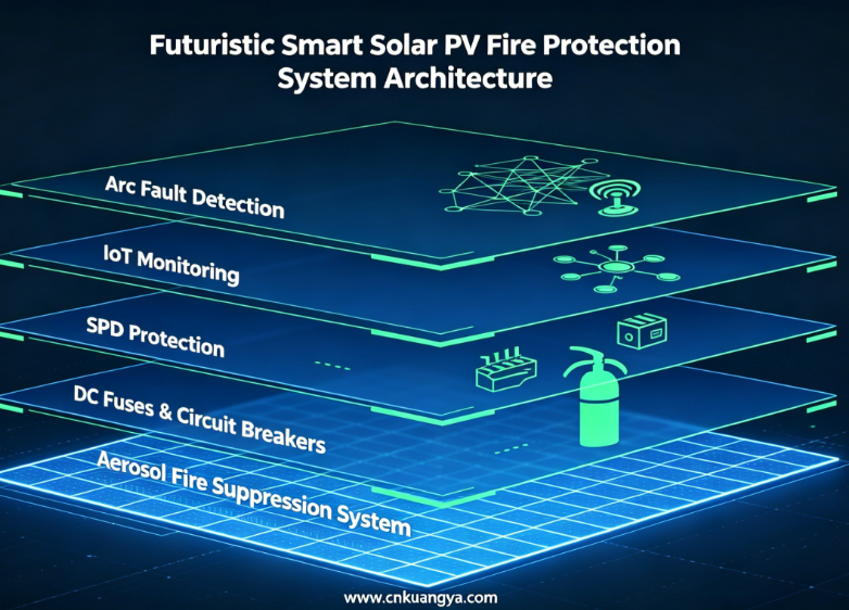
Modern PV systems are shifting from passive protection to intelligent active fire prevention systems.
AFCI technology detects abnormal DC waveform patterns and identifies arc conditions before ignition occurs.
Once detected, the system automatically disconnects affected circuits.
IoT systems enable real-time monitoring of:
This allows predictive maintenance rather than reactive repair.
Aerosol suppression is increasingly used inside PV distribution boxes.
Key advantages:
It is particularly suitable for high-value EPC solar projects.
These systems allow remote or automatic disconnection of faulty strings or distribution boxes during abnormal events.
This significantly reduces fire escalation risk.
Modern EPC projects are increasingly adopting a combined strategy:
Detection + Protection + Suppression + Remote Isolation
This reduces reliance on manual intervention, which is often too slow in DC fire scenarios.
A complete fire prevention system must integrate multiple layers into a unified architecture.
| Ebene | Funktion | Komponente |
|---|---|---|
| Erkennungsebene | Identifizierung von abnormalem Verhalten | Sensoren, AFCI-Systeme |
| Steuerungsebene | Analysieren und reagieren | Überwachungssteuerung |
| Schutzschicht | Fehlerstrom unterbrechen | Fuses, breakers, SPDs |
| Trennschicht | Trennsystem | DC-Trennschalter |
| Unterdrückungsschicht | Extinguish fire | Aerosol fire system |
The system is based on redundancy:
If one layer fails, another layer must still prevent escalation.
This is now considered standard practice in high-end PV EPC design.
Despite advanced technology availability, many fire incidents still occur due to avoidable mistakes.
| Irrtum | Ergebnis |
|---|---|
| Ignoring torque specifications | Terminal overheating |
| Unterdimensionierte Auswahl von Überspannungsschutzgeräten (SPD) | Surge-induced breakdown |
| Mangelhafte Gehäuseabdichtung | Moisture short circuit |
| Fehlende thermische Inspektion | Undetected hotspot growth |
| No long-term maintenance plan | Progressive system failure |
Most Solar PV Fire incidents are not caused by sudden failure.
Sie werden verursacht durch:
“Small electrical and mechanical issues accumulating over time until system tolerance is exceeded.”
Fire protection strategies for photovoltaic systems should integrate both electrical fault prevention and early-stage suppression in enclosed electrical environments, as recommended by NFPA-Sicherheitsrichtlinien für Photovoltaikanlagen.
Solar PV Fire risk is not the result of a single failure point, but a combination of electrical, mechanical, and environmental stress factors acting over time.
The most critical insight from real EPC projects is:
Wirksam Solar PV Fire Prevention requires a full system approach combining:
Only through this layered engineering strategy can long-term PV system safety be achieved.
Loose DC connections leading to arc faults inside distribution boxes.
No. SPDs reduce surge-related risks but cannot prevent all fire causes such as loose connections or aging.
Because they are the convergence point of multiple DC strings under continuous electrical load.
Thermal inspection should be conducted quarterly, especially in commercial and utility-scale systems.
For high-value EPC installations, yes. It provides fast automatic suppression in enclosed electrical spaces.
Focusing only on equipment quality while ignoring installation torque control and long-term maintenance.
