WengYang Industrial Zone Yueqing Wenzhou 325000
Work Hours
Monday to Friday: 7AM - 7PM
Weekend: 10AM - 5PM
WengYang Industrial Zone Yueqing Wenzhou 325000
Work Hours
Monday to Friday: 7AM - 7PM
Weekend: 10AM - 5PM

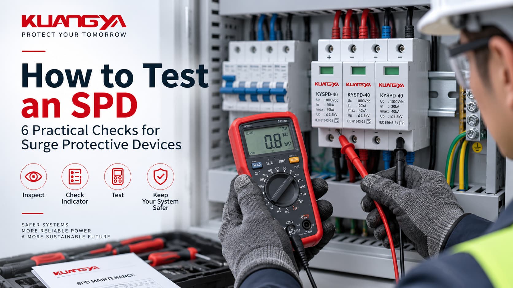
Knowing how to test an SPD is not as simple as placing a multimeter across its terminals and checking for continuity.
A surge protective device is designed to respond to short-duration overvoltage events that are far beyond the normal output of a handheld meter. This means some basic checks can be performed on site, but they cannot fully prove that an SPD can still handle its rated surge current or maintain its original voltage protection level.
In practice, SPD testing usually starts with simple checks: inspect the device, look at the status indicator, check any remote signaling contact, and identify obvious electrical abnormalities. More detailed assessment may require a dedicated SPD or MOV tester.
And if an SPD is already showing a clear failure condition, testing may not be necessary at all. Replacing the failed protection module can be the more practical solution.
This guide explains how to test an SPD, what a multimeter can and cannot tell you, when insulation testing needs special care, and which SPD parameters cannot normally be verified in the field.
Yes, an SPD can be checked and, in some cases, tested.
However, it is important to separate three different things:
These are not the same.
A technician may be able to confirm that:
But these checks do not reproduce a lightning impulse or high-energy surge.
A normal handheld multimeter cannot generate the standardized surge-current waveforms used to establish parameters such as In, Imax, Iimp or Up.
| Check or Test | What It Can Tell You | What It Cannot Prove |
|---|---|---|
| Visual inspection | Physical damage, overheating, melting or deformation | Internal surge performance |
| Status indicator | Whether the SPD is showing its normal or failure state | Full condition of the MOV |
| Remote contact | Whether alarm/status signaling works as expected | Surge-current capability |
| Multimeter | Wiring, contacts and some obvious abnormal electrical conditions | Up, In, Imax or Iimp |
| Dedicated SPD / MOV tester | Selected component characteristics and possible degradation | Complete standardized surge performance |
| Laboratory impulse testing | Performance under controlled surge conditions | Routine field condition only |
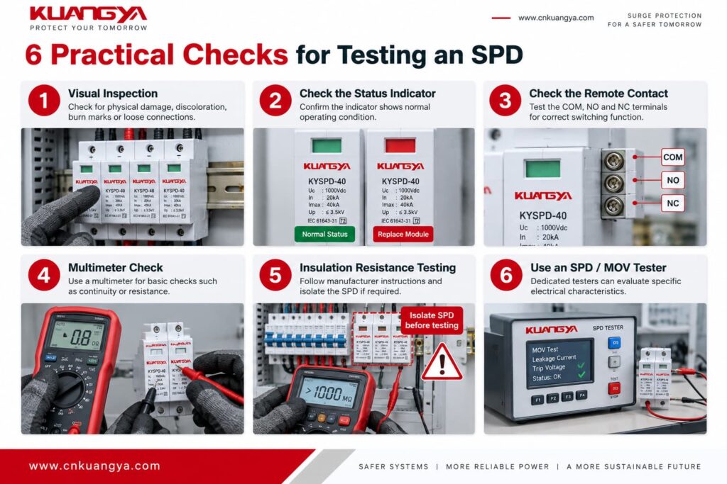
This distinction is important because an SPD may pass a simple low-voltage check without proving that it still performs exactly as it did when new.
So when someone asks:
“Is my SPD still good?”
the answer depends on what they are trying to verify.
For routine maintenance, a visual and functional condition check may be enough.
For component-level diagnosis, additional testing may be useful.
For confirmation of the original surge ratings, professional impulse testing is required.
Before carrying out any electrical measurement, the SPD and the circuit around it must be treated as energized electrical equipment until proper isolation has been confirmed.
Testing procedures also depend on:
Do not remove an SPD module from an energized installation simply to perform a measurement.
Before working on the SPD:
For PV systems, remember that DC conductors may remain energized whenever the array is exposed to sufficient light, even when other parts of the system have been switched off.
If you are not qualified to work on the installation, SPD testing should be carried out by a qualified electrical professional.
Before reaching for any test instrument, inspect the SPD.
A surprising number of SPD problems can be identified visually.
Look for:
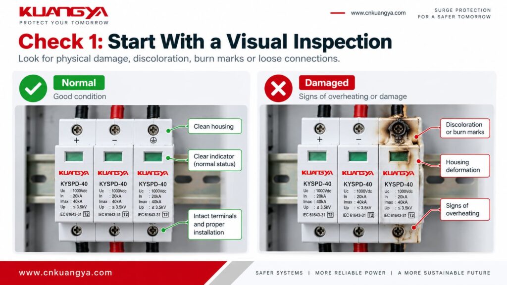
Also inspect the wiring around the SPD.
Sometimes the problem is not the protection element itself.
A loose terminal, damaged conductor or poor connection can create heating and discoloration that may initially appear to be an SPD failure.
If the SPD has suffered severe physical or thermal damage, there is usually little value in performing a basic resistance test just to decide whether it should remain in service.
The device should be isolated and investigated, and the damaged module or SPD replaced as required.
Most modular power SPDs include a mechanical or electrical status indication.
Depending on the design, the indicator may show:
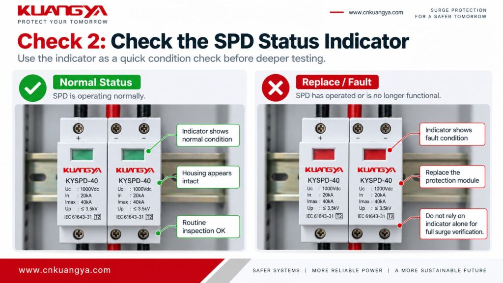
However, you should not assume that every SPD uses exactly the same color convention.
Always check the markings or manufacturer’s instructions for the specific model.
No.
A normal indicator is very useful, but it should not be interpreted as a complete laboratory test of the protection element.
The indicator normally reflects the condition of the SPD’s internal monitoring or disconnection mechanism.
If you are trying to determine whether an SPD is already showing signs of failure, see our previous guide:
It does not directly measure every electrical characteristic of the MOV or reproduce a surge event.
For a deeper explanation of what a normal status window can and cannot confirm, see our guide to the SPD green indicator.
How to Know If an SPD Is Bad? 7 Signs of Surge Protector Failure
That article focuses on identifying a bad SPD. This guide focuses on what can be checked after you decide further testing may be useful.
Many SPDs designed for distribution boards, industrial equipment, solar systems and remote monitoring applications are available with an auxiliary signaling contact.
For example, some modular SPDs combine a local green/red status indicator with a remote fault indicator contact for external monitoring.
You may see terminals marked:
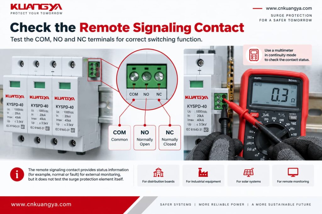
or similar markings depending on the manufacturer.
The signaling contact changes state when the SPD’s monitored condition changes.
This allows the SPD status to be sent to:
After safely isolating the relevant circuits, the auxiliary contact can be checked according to the terminal diagram supplied by the SPD manufacturer.
A multimeter in continuity or resistance mode may be used to determine whether the expected NO or NC contact is closed in the SPD’s present state.
For example, the technician may compare:
The exact contact logic should always be taken from the product documentation.
Testing the remote contact is not the same as testing the SPD protection element.
A correctly operating auxiliary contact only confirms that the signaling mechanism is behaving as expected.
It does not prove that the SPD still has its original:
Think of the remote contact as a status reporting feature, not as a surge generator or MOV analyzer.
This is one of the most common questions about how to test an SPD.
The short answer is:
When learning how to test an SPD with a multimeter, it is important to understand that a multimeter is useful only for limited checks.
A digital multimeter typically applies a relatively small measurement voltage.
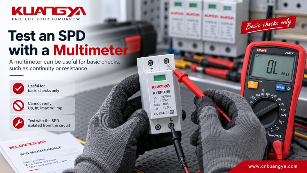
An SPD, by contrast, is designed to react when the voltage rises well above the normal operating level.
This difference is extremely important.
Continuity mode is useful for checking conductors, switches, fuses and auxiliary contacts.
It is much less useful as a complete test of a voltage-limiting SPD.
For an MOV-based SPD, the MOV normally presents a very high resistance at voltages far below its operating threshold.
Therefore, a normal MOV protection path may appear open or very high resistance when checked with an ordinary multimeter.
That does not mean that the MOV cannot conduct during an actual surge.
During a sufficiently high overvoltage, its electrical behavior changes dramatically and it begins diverting surge current.
A multimeter cannot reproduce that condition.
It may help identify certain obvious problems, depending on the SPD design, such as:
However, the reading has to be interpreted according to the actual circuit.
You should not use a rule such as:
“No continuity means the SPD is bad.”
That is not a valid general test for MOV-based SPDs.
You can physically connect a resistance meter to an isolated component or suitable test points, but the measured value needs careful interpretation.
A healthy MOV normally has very high resistance under ordinary low-voltage conditions.
However, an assembled SPD may also contain:
As a result, there is no universal resistance value such as:
“A good SPD must measure exactly X megohms.”
The correct result depends on the internal design.
A very low resistance where the circuit should normally be high impedance may indicate a serious fault, but a high-resistance reading alone does not prove that the SPD is healthy.
This table is more useful than trying to apply one fixed resistance value to every SPD.
| Multimeter Result | Possible Meaning | Does It Prove the SPD Is Good? |
|---|---|---|
| OL / very high resistance across an MOV path | May be normal because the meter voltage is below the MOV operating region | No |
| Very low resistance where high impedance is expected | May indicate an abnormal short or failed component | No |
| Expected continuity on a remote contact | The signaling contact is behaving as expected | No |
| Unexpected remote-contact state | Possible signaling fault or SPD status change | No |
| Normal wiring continuity | External connection is intact | No |
| No obvious electrical abnormality | No simple low-voltage fault was found | No |
The key point is simple:
A normal multimeter result can rule out some obvious faults, but it cannot prove the SPD’s complete surge-protection performance.
Imagine testing a fire extinguisher by checking whether its handle is still attached.
That tells you something useful about its condition.
But it does not prove how effectively it would perform in a real fire.
The same principle applies to a basic multimeter check of an SPD.
The meter cannot confirm how the device will behave during an 8/20 µs or 10/350 µs impulse.
It also cannot directly verify the SPD’s original surge-current rating.
Therefore:
Normal appearance + normal indicator + normal low-voltage meter readings = useful maintenance information
but:
they do not equal complete surge-performance verification.
This is one of the most important points to understand when learning how to test an SPD with a multimeter.
Another common maintenance situation occurs when technicians are not specifically trying to test the SPD.
Instead, they are performing an insulation resistance test on the electrical installation.
This is where an SPD can create problems if it is not considered before testing.
Insulation resistance testers — often called megohmmeters or “Meggers” — apply a much higher DC test voltage than a normal multimeter.
Depending on the installation test, this may be hundreds of volts or more.
That voltage can interact with surge protection components.
Do not automatically assume that it should.
An SPD may influence an insulation resistance test or may be stressed by an inappropriate test voltage.
Therefore, before carrying out an insulation resistance test:
Electrical installation verification should also follow the applicable requirements of IEC 60364-6 and any national installation rules.
Do not simply apply a high insulation-test voltage across an installed SPD without checking whether the device is designed to tolerate that procedure.
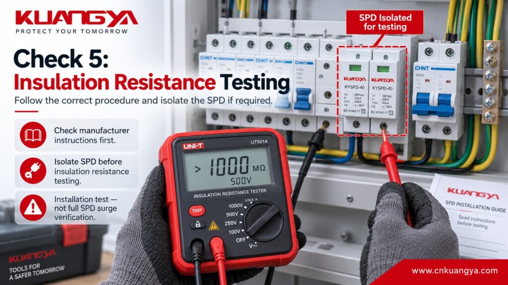
For example, Eaton states in its SPD Max installation instructions that dielectric, Megger or high-potential testing with the SPD connected can damage the device, and the SPD should be disconnected before such testing.
An SPD intentionally contains voltage-dependent components connected between conductors that would otherwise be electrically separated under normal operating conditions.
When a sufficiently high test voltage is applied, those components may begin to influence the measurement.
The tester may then show a lower resistance than expected.
A technician could incorrectly conclude:
“The cable insulation is bad.”
when the SPD itself is influencing the test circuit.
The opposite problem is also possible: inappropriate test conditions may overstress sensitive surge protection components.
So an insulation resistance test should primarily be treated as an installation insulation test, not as a convenient way to determine whether an SPD is healthy.
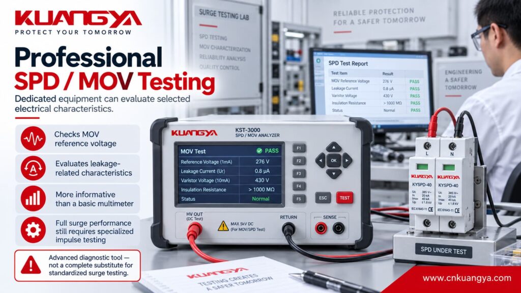
When visual inspection, indicator status and basic meter checks are not enough, a dedicated SPD or MOV tester may provide more useful information.
Unlike a standard multimeter, these devices can apply a controlled voltage appropriate for testing certain surge protection components.
Depending on the tester and SPD design, professional test equipment may check characteristics such as:
This is fundamentally different from simply putting a handheld meter into resistance mode.
An MOV does not suddenly change from completely insulating to completely conducting at one perfect voltage.
Its current-voltage characteristic is nonlinear.
For testing and manufacturing purposes, a reference voltage can be specified at a defined current.
If the MOV has degraded significantly, its electrical characteristics may shift.
A suitable tester can therefore provide more meaningful information than a simple continuity measurement.
However, the measured result still has to be compared with:
A random voltage reading without a known acceptable range does not provide much diagnostic value.
Not necessarily.
Even a dedicated MOV test does not automatically reproduce every standardized surge test that was used during product qualification.
An SPD is more than just one MOV.
Depending on the design, it may include:
A component-level test can therefore be useful without being equivalent to a complete SPD type test.
Professional SPD testing goes far beyond continuity or resistance.
Depending on the SPD type and applicable standard, testing may evaluate parameters such as:
These tests require specialized equipment capable of producing controlled high-current and high-voltage impulses.
For photovoltaic DC SPDs, IEC 61643-31 specifies requirements, performance characteristics, safety requirements and standardized test methods for SPDs used on the DC side of PV installations.
That is why there is a major difference between:
checking an SPD in a distribution board
and
verifying the declared performance of an SPD in a laboratory.
The second requires purpose-built surge generators, measurement systems and standardized test procedures.
Normally, these are not parameters that an electrician verifies with an ordinary handheld meter during routine maintenance.
Understanding the difference helps prevent misleading conclusions.
| SPD Parameter | Can It Normally Be Checked With a Multimeter on Site? | What It Means |
|---|---|---|
| Uc / Ucpv | The marked value can be checked against the system voltage, but this is not a performance test | Maximum continuous operating voltage |
| Up | No | Voltage protection level under specified surge test conditions |
| In | No | Nominal discharge current, commonly associated with an 8/20 µs waveform |
| Imax | No | Maximum discharge current associated with an 8/20 µs waveform |
| Iimp | No | Impulse current used particularly for Type 1 SPD testing, associated with a 10/350 µs waveform |
The 8/20 µs and 10/350 µs waveforms require dedicated impulse-current test equipment.
They are fundamentally different from the small test current supplied by a handheld meter.
No.
Up, or the voltage protection level, describes the voltage limitation achieved by the SPD under defined test conditions.
It is not simply a static voltage that can be measured by connecting a multimeter across an unpowered SPD.
Testing limiting voltage requires an appropriate surge impulse and measurement setup.
No.
In represents a nominal discharge current under a standardized impulse waveform.
For many Type 2 SPD specifications, the relevant current waveform is 8/20 µs.
A multimeter does not produce this surge current.
No.
Imax represents a higher discharge-current capability and is also associated with high-current impulse testing rather than ordinary low-voltage resistance measurements.
No.
Iimp is particularly important for Type 1 SPDs designed for lightning-current applications.
It is associated with a 10/350 µs impulse waveform.
Generating and safely measuring such currents requires specialized surge-testing equipment.
If you want to understand these values in more detail, see our guide to DC SPD Specifications, where we explain Uc, Up, In, Imax and other common markings found on surge protective devices.
Use these five questions to decide whether to continue with basic checks, consider deeper SPD / MOV testing, replace the SPD, or use laboratory impulse testing.
Look at the SPD housing, terminals and surrounding wiring before using a test instrument.
Follow the markings or manufacturer instructions for your specific SPD.
This does not automatically mean the SPD has failed, but it may justify closer inspection.
Examples include wiring, remote-contact status, obvious shorts, overheating or loose connections.
Choose the level of information you actually need from the test.
The SPD already shows a clear failure condition, such as serious physical damage or a defined fault / replacement indication. Further basic multimeter testing is unlikely to add useful information.
Follow the manufacturer’s replacement instructions and investigate the cause if there is burning, melting, overheating or damaged wiring.There is no clear evidence of SPD failure yet, but the current condition has not been fully established. Start with visual inspection, the status indicator, wiring, remote signaling contacts if fitted, and other appropriate low-voltage checks.
A multimeter can help with limited checks, but it cannot prove the full surge performance of the SPD.No clear failure sign or obvious abnormal condition was identified, and you only need a routine field condition check. Continue normal inspection and maintenance according to the SPD manufacturer’s instructions.
A normal indicator and normal basic checks do not independently verify the original Up, In, Imax or Iimp ratings.The SPD does not show a clear end-of-life condition, but deeper diagnosis may be useful because of an abnormal basic check, a known major surge event, or the need to assess the condition of the MOV or protection element more closely.
Use suitable SPD / MOV test equipment and compare the results with manufacturer data or applicable product limits.If you need to verify rated surge parameters such as Up, In, Imax or Iimp, a handheld multimeter or routine field tester is not enough. These parameters require specialized surge / impulse test equipment and controlled test procedures.
Field condition checks and MOV testing are useful for maintenance, but they are not substitutes for standardized impulse-performance testing.Testing is useful when the condition of the SPD is uncertain.
But there are situations where additional basic testing adds little value.
The following table provides a practical way to decide whether further testing makes sense.
| SPD Condition | Test Further? | Recommended Action |
|---|---|---|
| Normal appearance + normal indicator | Usually not necessary during routine maintenance | Continue normal inspection schedule |
| Normal appearance but condition is uncertain | Possibly | Use suitable diagnostic testing if needed |
| Failure / replacement indication | Usually no | Replace according to manufacturer instructions |
| Burned or melted housing | No | Isolate and replace |
| Serious deformation or overheating | No | Investigate the cause and replace the damaged SPD |
| Thermal disconnector operated | No | Replace the protection module |
| Unexpected low-resistance fault | Further investigation required | Do not re-energize until the fault is understood |
| After a major surge but no visible failure | Depends on the application | Inspect the SPD and consider deeper testing where protection is critical |
This is an important maintenance principle:
Testing is most useful when the SPD condition is uncertain. Clear failure conditions usually call for replacement rather than repeated basic measurements.
If the manufacturer’s status indicator clearly shows that the protection module has reached its replacement condition, follow the manufacturer’s instructions.
There is usually no reason to keep performing basic resistance measurements in an attempt to “prove” that the failed module is still usable.
Physical damage indicates that the SPD has experienced abnormal thermal or electrical stress.
Do not return a visibly damaged SPD to service based only on a normal resistance reading.
Many MOV-based SPDs incorporate thermal protection designed to disconnect an overstressed protection element.
If the internal disconnection mechanism has operated, the module normally requires replacement.
An SPD showing a persistent low-resistance fault condition where one should not exist requires investigation and should not simply be re-energized.
Always give priority to the manufacturer’s maintenance and replacement instructions for the specific product.
For many modular SPDs, the protection cartridge is designed to be replaceable.
Where the module is relatively inexpensive and its condition is genuinely uncertain, replacing it can be more practical than performing extensive diagnostic testing.
This is particularly true in systems where downtime or loss of surge protection has a high cost.
Here is a simple field checklist for how to test an SPD during maintenance.
Check:
If the SPD voltage rating itself may be incorrect for the PV system, check our DC SPD voltage selection guide before deciding whether the problem is product failure or incorrect selection.
Follow appropriate electrical safety and lockout procedures before removing covers, conductors or protection modules.
Check for:
If there is serious physical damage, replacement may already be required.
Compare the indicator with the markings or manufacturer’s documentation.
Do not assume every manufacturer uses the same colors.
Compare:
Use the manufacturer’s contact diagram.
A multimeter may help investigate:
Do not interpret a simple high-resistance or open-circuit reading as proof that the SPD can still handle its rated surge current.
A suitable SPD or MOV tester may be needed to examine reference voltage or other component characteristics.
Compare results with manufacturer specifications rather than using arbitrary pass/fail values.
If the SPD has:
follow the manufacturer’s replacement procedure.
For technicians who need a fast answer, the entire process can be reduced to one simple decision path.
| Question | If Yes | If No |
|---|---|---|
| Is there visible burning, melting or serious damage? | Replace and investigate the cause | Continue checking |
| Does the indicator show the defined failure state? | Replace the affected module | Continue checking |
| Is the remote contact inconsistent with the documented SPD state? | Investigate the SPD and signaling circuit | Continue checking |
| Does a basic meter test show an obvious abnormal short? | Investigate before re-energizing | Do not assume the SPD is fully verified |
| Is deeper confirmation required? | Use suitable SPD/MOV test equipment | Routine inspection may be sufficient |
| Do you need to verify Up, In, Imax or Iimp? | Laboratory/impulse testing is required | Field checks may be enough |
Yes, but only for limited checks.
A multimeter can help inspect wiring, auxiliary contacts and certain obvious abnormal conditions.
It cannot reproduce an actual surge or confirm the SPD’s In, Imax, Iimp or Up ratings.
There is no universal yes-or-no answer.
It depends on which terminals are being measured and how the SPD is designed.
A voltage-limiting MOV protection path may normally appear as very high resistance at the low measurement voltage of a multimeter.
An auxiliary remote contact, however, may intentionally show continuity between COM and either NO or NC depending on the SPD state.
Always interpret continuity measurements using the product circuit diagram.
There is no universal resistance value for all SPDs.
Different devices contain different protection and monitoring components.
An MOV normally presents a high resistance at low voltage, but the complete SPD may contain additional circuits that affect a meter reading.
Use manufacturer data or appropriate dedicated testing procedures rather than relying on a generic resistance number.
Do not assume that you can.
SPDs may affect insulation resistance readings or may be damaged by inappropriate insulation-test voltages.
The installation requirements and product manufacturer may require the SPD to be disconnected or isolated before the test.
Always check the applicable procedure before applying an insulation-test voltage.
For meaningful MOV testing, dedicated equipment can apply a controlled voltage and measure characteristics such as reference voltage at a specified current.
This gives much more information than a simple low-voltage continuity test.
However, acceptable values must still be compared with the specification of the particular MOV or SPD.
No.
Up is associated with the SPD’s limiting performance under specified surge conditions.
A normal multimeter cannot generate the required impulse.
Potentially, yes.
Visual inspection is useful for detecting obvious failures, but not every change in the electrical characteristics of a protection component produces visible damage.
This is one reason dedicated test equipment may be used in installations where protection availability is particularly important.
A normal status indicator is an important maintenance check, but it is not the same as repeating the original standardized surge tests.
The indicator tells you the condition recognized by the SPD’s monitoring mechanism.
It does not independently measure every surge-performance parameter.
Always interpret the indicator according to the specific product design.
Age alone does not establish a universal replacement date for every SPD.
The decision should consider:
If the device already shows its defined end-of-life condition, replacement is normally more appropriate than trying to extend its service based on a simple multimeter test.
The most important part of understanding how to test an SPD is knowing the limits of each testing method.
For routine field maintenance, start with the simplest checks:
A multimeter is useful, but it cannot reproduce a lightning or switching surge.
Therefore, continuity and resistance measurements should never be treated as complete proof that an SPD still meets its original Up, In, Imax or Iimp performance.
Insulation resistance testing also requires special attention because an installed SPD may influence the measurement or be affected by an inappropriate test procedure.
Most importantly, testing should support a practical maintenance decision.
If the SPD looks normal and its monitoring functions show normal operation, routine inspection may be sufficient.
If its condition is uncertain, specialized testing can provide additional information.
But if the device already shows a clear failure condition, thermal damage or an operated disconnection mechanism, replacement is usually the more sensible next step.
In the next guide, we will look at another common question:
When Should an SPD Be Replaced? Lifespan, Surge Events and Warning Signs

