Промышленная зона Вэньян Юэцин Вэньчжоу 325000
Рабочие часы
Понедельник - пятница: 7AM - 7PM
Выходные: 10AM - 5PM
Промышленная зона Вэньян Юэцин Вэньчжоу 325000
Рабочие часы
Понедельник - пятница: 7AM - 7PM
Выходные: 10AM - 5PM

5-контактное реле - одно из наиболее часто используемых электрических коммутационных устройств в автомобильных системах, промышленной автоматике, оборудовании для возобновляемых источников энергии и электронных схемах управления. 5-контактное реле - это тип электромеханическое реле предназначен для безопасного управления сильноточными электрическими нагрузками с помощью слаботочных сигналов управления. Оно позволяет слаботочному сигналу безопасно управлять сильноточной электрической нагрузкой. Благодаря своей гибкости и надежности 5-контактное реле стало важным компонентом в современной электротехнике.
По сравнению со стандартным выключателем, реле обеспечивает лучшую защиту, возможность автоматизации и электрическую изоляцию. Во многих системах прямое включение сильноточных устройств может привести к повреждению выключателей, перегреву проводки или снижению безопасности. Реле решает эти проблемы за счет использования электромагнитного управления.
5-контактное реле особенно популярно, поскольку содержит как нормально разомкнутые (NO), так и нормально замкнутые (NC) контакты, обеспечивая пользователям большую гибкость при подключении. Они широко используются в автомобилях, солнечных системах, промышленных панелях управления, системах безопасности и проектах домашней автоматизации.
В этом руководстве мы расскажем о принципе работы, конфигурации контактов, способах подключения, применении, процессе тестирования, методах устранения неисправностей и часто задаваемых вопросах, связанных с 5-контактными реле.
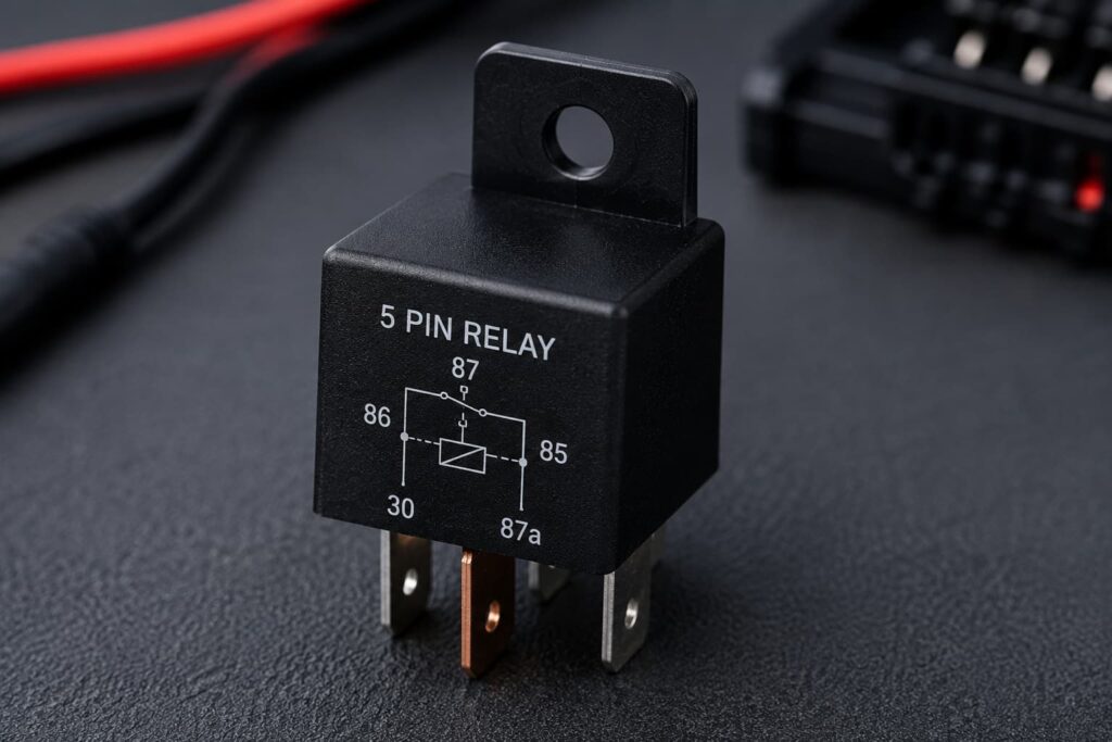
5-контактное реле - это электромеханический переключатель, который использует электромагнитную силу для размыкания или замыкания электрических контактов. Оно содержит пять клемм, которые позволяют реле управлять электрическими цепями.
Пять терминалов включают в себя:
Когда на катушку реле подается напряжение, внутри реле создается магнитное поле. Это магнитное поле перемещает внутренний якорь, который изменяет соединение между контактами.
Основная задача реле - обеспечить безопасное управление большой нагрузкой с помощью небольшого электрического сигнала.
Понимание структуры реле помогает пользователям правильно подключать и устранять неисправности устройства.
При подаче напряжения катушка создает магнитное поле. системы релейного управления широко используются в оборудовании промышленной автоматизации и интеллектуальных электрических приложениях.
Якорь - это подвижная металлическая деталь, которая переключает контакты.
Пружина возвращает якорь в исходное положение, когда катушка теряет энергию.
Контакты размыкают или замыкают электрическую цепь.
Внешний корпус защищает реле от пыли, вибрации и влаги.
Большинство реле имеют стандартную систему нумерации выводов.
| Номер штырька | Функция | Описание |
|---|---|---|
| 85 | Клемма катушки | Обычно подключен к земле |
| 86 | Клемма катушки | Подключено к напряжению запуска |
| 30 | Общий терминал | Основной вход питания |
| 87 | Нормально открытый (NO) | Подключено, когда реле включено |
| 87a | Нормально закрытый (NC) | Подключено, когда реле выключено |
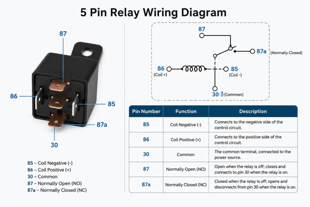
Эти два контакта управляют катушкой реле. Подача напряжения на них активирует реле.
Контакт 30 является общей клеммой и обычно принимает входящее питание.
Вывод 87 соединяется с выводом 30, когда реле находится под напряжением.
Вывод 87a остается подключенным к выводу 30, когда на реле не подается напряжение.
Реле работает на электромагнитных принципах.
Когда на катушку не подается питание:
Когда на катушку подается напряжение:
| Состояние реле | Активное соединение | Результат |
|---|---|---|
| Катушка выключена | 30 → 87a | Нормально закрытый активный |
| Катушка ВКЛ | 30 → 87 | Нормально открытая активная |
Многие люди путают эти два типа реле.
| Характеристика | 4-контактное реле | 5-контактное реле |
|---|---|---|
| Выходные контакты | Один | Два |
| NC Контакт | Нет | Да |
| Гибкость | Основные | Расширенный |
| Варианты подключения | Ограниченный | Более гибкий |
Дополнительная нормально-закрытая клемма дает 5-контактному реле дополнительные возможности управления.
Автомобильные приложения - самое распространенное применение для 5-контактных реле. Многие автомобильные системы также требуют надежной работы. решения для защиты цепей для обеспечения стабильных электрических характеристик.
Реле широко используются в промышленных системах управления.Применение промышленных реле продолжают играть важную роль в современных системах автоматизации, производства и электробезопасности.
Приложения включают:
В солнечных системах и системах накопления энергии используются реле:
В умных домах используются реле:
Цепь управления остается отделенной от цепи нагрузки.
Маленькие выключатели могут безопасно управлять большими электрическими нагрузками.
Клеммы NO и NC обеспечивают множество вариантов управления.
Реле уменьшают перегрев и повреждение выключателей.
Реле обеспечивают дистанционное и автоматическое управление.
Хотя реле полезны, они также имеют некоторые ограничения.
Движущиеся части со временем изнашиваются.
Большинство реле издают щелкающий звук.
Механические реле работают медленнее, чем электронные переключатели.
Электрическая дуга может повредить контакты при переключении.
5-контактное реле 12 В - самый популярный тип в автомобильных системах.
| Параметр | Типичное значение |
|---|---|
| Напряжение катушки | 12 В DC |
| Контактный рейтинг | 30A-40A |
| Время переключения | 5-15 мс |
| Рабочая температура | от -40°C до +85°C |
Правильная проводка - залог безопасности и производительности.
| Контакт реле | Соединение |
|---|---|
| 85 | Земля |
| 86 | Триггерный переключатель |
| 30 | Вход питания |
| 87 | Выходная нагрузка |
| 87a | НЗ выход |
В автомобиле:
Когда переключатель активирует реле, питание подается на противотуманные фары.
Проверка реле важна при техническом обслуживании.
Найдите все пять клемм.
Проверьте сопротивление между контактами 85 и 86.
Подайте номинальное напряжение на катушку.
Вы должны услышать щелчок.
Для проверки используйте мультиметр:
| Тест | Ожидаемый результат |
|---|---|
| Сопротивление катушки | Стабильное считывание |
| Щелчок реле | Слышимый звук |
| Нет контакта | Непрерывность при включении |
| Контакт NC | Непрерывность в выключенном состоянии |
Превышение силы тока может привести к повреждению контактов.
Катушка реле может перегореть.
Плохое соединение может вызвать перебои в работе.
Влага может разъедать клеммы реле.
Контакты могут свариться из-за дуги.
| Проблема | Возможная причина | Решение |
|---|---|---|
| Реле не щелкает | Отсутствие напряжения на катушке | Проверьте источник питания |
| Загрузка не работает | Поврежденные контакты | Замените реле |
| Перегрев реле | Избыточный ток | Используйте реле с более высоким номиналом |
| Болтовня реле | Низкое напряжение | Стабилизируйте источник питания |
Диод защищает схему от скачков напряжения, создаваемых катушкой.
Предохранители защищают от перегрузки по току.
Хорошее охлаждение предотвращает перегрев.
Устройства защиты от импульсных перенапряжений помогают снизить ущерб от переходных напряжений.Высококачественные устройства защиты от перенапряжения обычно устанавливаются вместе с релейными системами для повышения электробезопасности и надежности оборудования.
Перед подключением всегда отключайте питание.
Неразмерные провода могут перегреться.
Никогда не превышайте технические характеристики реле.
Прочное крепление предотвращает повреждение от вибрации.
Влага может повредить внутренние контакты.
5-контактное реле позволяет слаботочному управляющему сигналу переключать сильноточную электрическую нагрузку.
Контакт 87 - нормально открытый, а контакт 87a - нормально закрытый.
Да. Просто оставьте вывод 87a неиспользованным.
Обычно это свидетельствует о нестабильном напряжении или недостаточном питании.
Срок службы реле зависит от тока нагрузки, частоты переключения и условий эксплуатации.
Стандартные электромеханические реле обычно не чувствительны к полярности, если в них нет внутреннего диода.
| Тип реле | Основное использование | Преимущества | Недостатки |
|---|---|---|---|
| 4-контактное реле | Базовое переключение | Простая проводка | Менее гибкий |
| 5-контактное реле | Расширенное управление | Размыкающие и замыкающие контакты | Более сложный |
| Твердотельное реле | Быстрое переключение | Бесшумная работа | Более высокая стоимость |
| Автомобильное реле | Автомобильные системы | Прочный | Удельное напряжение |
| Промышленное реле | Системы автоматизации | Высокая надежность | Большой размер |
Даже с развитием современной электроники реле остаются чрезвычайно важными, поскольку обеспечивают:
В автомобильных системах, промышленном оборудовании, оборудовании для возобновляемых источников энергии и интеллектуальных системах автоматизации реле продолжают играть важнейшую роль.
5-контактное реле является одним из наиболее универсальных и широко используемых электрических коммутационных устройств в современных электрических системах. Его способность безопасно управлять сильноточным оборудованием с помощью слаботочных сигналов делает его незаменимым для автомобильной электроники, промышленной автоматизации, солнечных систем и проектов домашней автоматизации.
Понимание конфигурации контактов реле, принципа работы, способов подключения, процесса тестирования и методов устранения неисправностей помогает инженерам, электрикам и техникам создавать более безопасные и надежные электрические системы.
По сравнению с базовым 4-контактным реле, 5-контактное реле обеспечивает большую гибкость, поскольку включает в себя как нормально разомкнутые, так и нормально замкнутые контакты. Это позволяет создавать более совершенные схемы управления.
Независимо от того, работаете ли вы с проводкой автомобиля, промышленными панелями управления, системами возобновляемой энергии или проектами электроники "сделай сам", выбор правильного реле и его правильная установка могут значительно повысить безопасность и производительность системы.Professional электрозащитные средства помогают обеспечить долгосрочную надежность промышленных систем и систем возобновляемых источников энергии.
По мере развития электрических технологий 5-контактные реле остаются надежным и экономичным решением для современных коммутационных приложений.

