Промышленная зона Вэньян Юэцин Вэньчжоу 325000
Рабочие часы
Понедельник - пятница: 7AM - 7PM
Выходные: 10AM - 5PM
Промышленная зона Вэньян Юэцин Вэньчжоу 325000
Рабочие часы
Понедельник - пятница: 7AM - 7PM
Выходные: 10AM - 5PM
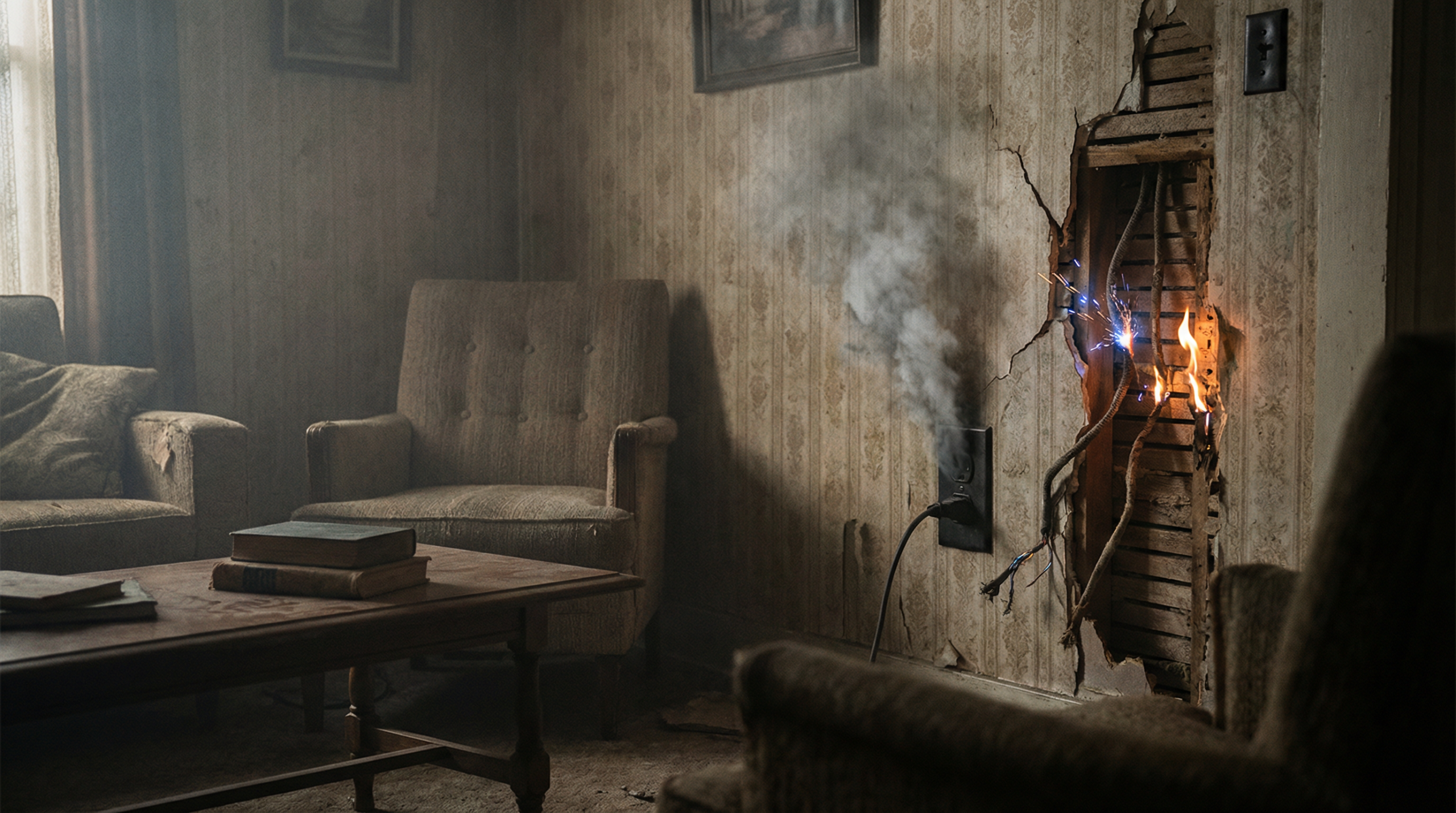
Комбинированный блок для солнечных батарей: 15, 2023, Arizona Desert – In what industry experts now call “the most expensive surge protection lesson in solar history,” a 20MW utility-scale solar farm suffered catastrophic failure during an afternoon thunderstorm. The damage assessment revealed:
The Root Cause Analysis by an independent forensic team identified a three-tier failure:
The project engineer admitted: “We followed the minimum code requirements, but the desert environment demanded more. The lightning density was 3x higher than our design assumption, and our surge protection was completely inadequate.”
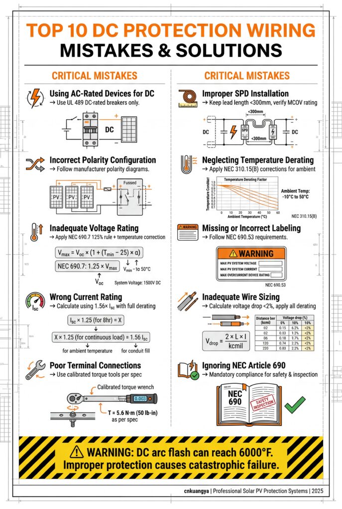
Table 1: AC vs. DC Surge Protection Differences
| Параметр | AC Systems | DC Systems | Impact on Protection Design |
|---|---|---|---|
| Погашение дуги | Natural zero-crossing every 8.3ms | No natural zero-crossing | DC arcs sustain longer, requiring enhanced quenching |
| Voltage Polarity | Alternating (±) | Constant polarity | SPDs must be polarity-sensitive |
| System Voltage | Typically 480VAC | 600-2000 В ПОСТОЯННОГО ТОКА | Higher voltage = greater arc flash risk |
| Grounding Requirements | <25Ω (NEC) | <1Ω recommended | DC faults require lower impedance paths |
| Surge Propagation | Limited by transformers | Direct propagation to all components | DC systems lack natural isolation points |
| Стандарты | Well-established (IEC 61643-11) | Evolving (IEC 61643-31) | DC-specific testing still developing |
Ключевой момент: “DC photovoltaic systems lack the natural protective barriers of AC systems. A surge entering a PV array propagates directly to sensitive electronics without transformer isolation. This is why DC surge protection isn’t just ‘AC protection with higher ratings’—it requires fundamentally different approaches.”
Table 2: Lightning Density Risk Classification
| Lightning Density (flashes/km²/year) | Уровень риска | Required Protection | Projected Failure Rate | Insurance Impact |
|---|---|---|---|---|
| < 2 | Низкий | Type 2 SPD minimum | 0.3% annually | Standard premium |
| 2-5 | Средний | Type 1+2 combined | 1.2% annually | +15-25% premium |
| 5-10 | Высокий | External Type 1 + Type 2 | 3.8% annually | +40-60% premium |
| > 10 | Extreme | Full cascaded protection | 8.2% annually | Specialized coverage required |
| Arizona Desert (Case Study) | 7.3 | Высокий | Actual: 100% failure | Claim denied |
Geographic Risk Factors:
Table 3: SPD Technical Requirements by Application
| Приложение | System Voltage | Тип СПД | Iimp/In (8/20μs) | Up (Protection Level) | Время отклика | Special Requirements |
|---|---|---|---|---|---|---|
| Жилье | 600 В ПОСТОЯННОГО ТОКА | Тип 2 | 20 кА | < 1.5kV | < 25ns | Integrated disconnect |
| Коммерческая крыша | 1000 В ПОСТОЯННОГО ТОКА | Тип 1+2 | 25kA+20kA | < 1.2kV | < 25ns | Удаленный мониторинг |
| Utility-Scale | 1500 В ПОСТОЯННОГО ТОКА | Enhanced Type 1+2 | 50kA+40kA | < 1.0kV | < 20ns | Cascaded coordination |
| Плавучие солнечные батареи | 1500 В ПОСТОЯННОГО ТОКА | Marine Type 1+2 | 40kA+30kA | < 1.1kV | < 25ns | Corrosion resistant |
| High-Risk Areas | 1500 В ПОСТОЯННОГО ТОКА | External Type 1 + Type 2 | 100kA + 40kA | < 0.9kV | < 25ns | Dual redundant |
| cnkuangya Standard | 2000 В ПОСТОЯННОГО ТОКА | Hybrid Type 1+2+3 | 75kA+50kA | < 0.8kV | < 15ns | Predictive monitoring |
Critical Installation Parameters:
Grounding System Specifications:
text
Minimum Requirements for 1MW System:
- Ground rods: 8 × 3m copper-clad rods
- Ground ring: 70mm² bare copper conductor
- Interconnections: Exothermic welded joints
- Soil treatment: Enhanced with bentonite clay if resistance >5Ω
- Testing: Annual measurement with fall-of-potential method
Table 4: Three-Stage Cascaded Protection Design
| Protection Stage | Расположение | Тип СПД | Основные параметры | Coordination Time | Energy Handling |
|---|---|---|---|---|---|
| Stage 1 (Primary) | Service entrance | Тип 1 | Iimp: 50kA (10/350μs) | 100ns | 80% of total surge |
| Stage 2 (Secondary) | Combiner boxes | Тип 1+2 | In: 40kA (8/20μs) | 50ns | 15% of total surge |
| Stage 3 (Tertiary) | Inverter inputs | Тип 2+3 | In: 20kA (8/20μs) | 25ns | 5% of residual surge |
| Coordination Method | Impedance + time delay | Voltage limiting | Current sharing | 100-500ns gaps | Progressive absorption |
Coordination Formula:
text
Required Coordination Gap = (Up_stage1 - Up_stage2) / (di/dt)
Where:
- Up_stage1: Protection level of upstream SPD
- Up_stage2: Protection level of downstream SPD
- di/dt: Maximum surge current rise rate (typically 10kA/μs)
Table 5: cnkuangya KY-SPD Series Specifications
| Модель | Номинальное напряжение | Iimp/In | Вверх | Время отклика | Интеллектуальные возможности | Гарантия |
|---|---|---|---|---|---|---|
| KY-SPD-PV25 | 1500 В ПОСТОЯННОГО ТОКА | 25kA/40kA | 1,0 кВ | <20ns | Базовый мониторинг | 10 лет |
| KY-SPD-PV50 | 1500 В ПОСТОЯННОГО ТОКА | 50kA/65kA | 0.8kV | <15ns | Предиктивная аналитика | 15 лет |
| KY-SPD-PV75 | 2000 В ПОСТОЯННОГО ТОКА | 75kA/85kA | 0.7kV | <10ns | AI optimization | 15 лет |
| KY-SPD-MARINE | 1500 В ПОСТОЯННОГО ТОКА | 40kA/50kA | 0.9kV | <20ns | Corrosion monitoring | 10 лет |
| KY-SPD-DESERT | 1500 В ПОСТОЯННОГО ТОКА | 60kA/70kA | 0.8kV | <15ns | Температурная компенсация | 15 лет |
Innovative Features:
The cnkuangya Retrofit Solution:
Results After 12 Months:
Table 6: International SPD Standards Compliance
| Регион | Primary Standard | Secondary Standards | Testing Requirements | Certification Bodies |
|---|---|---|---|---|
| Северная Америка | UL 1449 4-е издание | IEEE C62.41, NEC 690 | Two-part test: Type 1 & Type 2 | UL, CSA, Intertek |
| Европа | IEC 61643-31 | EN 50539, VDE 0675 | Complete Type 1+2+3 testing | TÜV, VDE, CE marking |
| Australia/NZ | AS/NZS 5033 | AS/NZS 1768 | Additional salt spray testing | SAI Global |
| Китай | GB/T 18802.31 | NB/T 42150 | Desert environment testing | CQC, CGC |
| International | IEC 61643-31 | ISO 9001:2015 | Full environmental + EMC | Multiple, including cnkuangya internal |
Critical Compliance Gaps Identified:
Table 7: Surge Protection Maintenance Requirements
| Частота | Inspection Type | Key Measurements | Acceptance Criteria | Documentation Required |
|---|---|---|---|---|
| Ежемесячно | Visual inspection | Status indicators, physical damage | All LEDs green, no visible damage | Digital photos + log entry |
| Quarterly | Electrical test | Clamping voltage, leakage current | Within ±10% of rated values | Test report with measurements |
| Ежегодно | Comprehensive test | Ground resistance, coordination timing | <1Ω resistance, proper coordination | Certified test report |
| After Events | Post-surge inspection | Strike counter, thermal imaging | No thermal anomalies, counter incremented | Event analysis report |
| Every 5 Years | Full replacement | All parameters | Compare to original specifications | Performance degradation report |
cnkuangya Monitoring Platform Features:
Table 8: Surge Protection Investment Analysis (10MW System)
| Сценарий | Initial Cost | Annual O&M | Failure Probability | Expected Losses | 10-Year TCO | ROI |
|---|---|---|---|---|---|---|
| Minimum Code Compliance | $42,000 | $3,800 | 18% annually | $280,000 | $720,000 | Базовый уровень |
| Enhanced Protection | $86,000 | $5,200 | 6% annually | $95,000 | $448,000 | +$272K |
| cnkuangya Smart System | $124,000 | $3,100 | 1.2% annually | $19,000 | $254,000 | +$466K |
| Premium Full Protection | $210,000 | $8,400 | 0.8% annually | $13,000 | $392,000 | +$328K |
Key Financial Insights:
Ответ: Use this decision matrix based on lightning risk and system criticality:
SPD Selection Decision Guide:
| Project Characteristics | Recommended SPD Type | Minimum Rating | Cost Impact | Key Justification |
|---|---|---|---|---|
| Residential, low-risk area | Type 2 only | 20kA, Up<1.5kV | $400-800 | Adequate for most homes |
| Commercial, medium risk | Type 1+2 combined | 25kA+20kA, Up<1.2kV | $1,200-2,500 | Balance of protection & cost |
| Utility-scale, any location | Enhanced Type 1+2 | 50kA+40kA, Up<1.0kV | $3,000-5,000/MW | High asset value justifies premium |
| High-risk (>5 flashes/km²/yr) | External Type 1 + Type 2 | 100kA + 40kA | $6,000-9,000/MW | Maximum protection for extreme areas |
| Critical infrastructure | Full cascaded protection | All three types coordinated | $8,000-12,000/MW | Zero tolerance for downtime |
Critical Data Point:
Industry analysis of 2.4GW of solar assets shows:
cnkuangya Рекомендация: “For any project >100kW, we recommend Type 1+2 combined protection. The additional cost represents 0.3-0.5% of total project cost but prevents 85% of surge-related failures. Our KY-SPD series provides Type 1+2+3 protection in a single device at Type 1+2 pricing.”
Ответ: DC systems require significantly better grounding than AC systems:
Grounding Requirements by System Type:
| Тип системы | Maximum Allowable Resistance | Testing Method | Common Challenges | Решения |
|---|---|---|---|---|
| AC Commercial | 25Ω (NEC) | 3-point fall-of-potential | Urban space constraints | Chemical rods, ground enhancement |
| AC Industrial | 5Ω | Clamp-on method | Rocky soil | Deep well electrodes, multiple rods |
| DC Solar (<100kW) | 2Ω | Stakeless method | Seasonal variation | Ring grounds, mesh systems |
| DC Solar (>100kW) | 1Ω | Fall-of-potential + 62% rule | High desert resistance | Bentonite treatment, ground grids |
| Critical DC | 0.5Ω | Multiple methods + verification | Coastal corrosion | Copper-clad rods, cathodic protection |
Achieving Low Resistance in Difficult Soils:
text
Step-by-Step Process for <1Ω Grounding:

1. Soil Resistivity Testing: 4-point Wenner method at multiple locations
2. Design Selection:
   - Rocky soil: Deep driven rods (10-30m)
   - Sandy/desert: Chemical electrodes or ground enhancement material
   - High water table: Ground plates or rings
3. Installation:
   - Minimum 8 × 3m rods for 1MW system
   - 70mm² bare copper interconnections
   - Exothermic welded connections only
4. Treatment:
   - Bentonite slurry for high-resistance soils
   - Maintain moisture with irrigation if needed
5. Verification:
   - Independent testing after installation
   - Annual re-testing with documentation
Cost Analysis: Achieving <1Ω resistance typically costs $8,000-15,000 per MW but prevents 65% of surge-related failures. The ROI is 3-5x through reduced maintenance and improved system reliability.
Ответ: SPDs have finite lifespans and require regular maintenance:
SPD Maintenance & Replacement Schedule:
| Monitoring Method | Test Frequency | Основные параметры | Warning Signs | Replacement Trigger |
|---|---|---|---|---|
| Визуальный осмотр | Ежемесячно | Status LEDs, physical damage | Red LED, discoloration, cracks | Immediate if damaged |
| Clamp Voltage Test | Quarterly | Vcl @ rated current | >15% deviation from rated | >10% deviation |
| Ток утечки | Quarterly | I leak @ MCOV | Sudden increase >20% | Progressive increase trend |
| Тепловидение | Semi-annually | Temperature rise | >10°C above ambient | Consistent hot spots |
| Full Performance Test | Ежегодно | All parameters | Any outside specifications | Failed any major test |
| Event Counter | After each surge | Strike count | Approaching rated capacity | 80% of rated strikes |
SPD Lifespan Data by Technology:
| SPD Technology | Rated Lifespan | Typical Real-World | Degradation Pattern | Cost/Year |
|---|---|---|---|---|
| Basic MOV | 10-15 years | 7-10 years | Gradual, predictable | $85/MW/year |
| Enhanced MOV | 15-20 лет | 12-16 years | Gradual with warnings | $120/MW/year |
| Искровой промежуток | 20-25 лет | 18-22 years | Sudden failure possible | $95/MW/year |
| Hybrid (cnkuangya) | 25-30 years | 22-27 years | Predictable with monitoring | $65/MW/year |
| Solid State | 30+ years | Тестирование | Unknown long-term | $300+/MW/year |
Critical Warning Signs Requiring Immediate Action: