Промышленная зона Вэньян Юэцин Вэньчжоу 325000
Рабочие часы
Понедельник - пятница: 7AM - 7PM
Выходные: 10AM - 5PM
Промышленная зона Вэньян Юэцин Вэньчжоу 325000
Рабочие часы
Понедельник - пятница: 7AM - 7PM
Выходные: 10AM - 5PM
Вы все сделали правильно. В вашем здании есть надежная 400-амперная сеть. В вашей серверной хранятся критически важные данные. На вашей производственной линии установлены чувствительные ПЛК и ЧРП. Затем, во вторник днем, близкий удар молнии или переключение в электросети вызывают мощный скачок напряжения в сети. Менее чем за секунду возникает хаос. Устройство SPD главной панели, которое вы считали адекватным, катастрофически выходит из строя. Скачок напряжения пробивает насквозь, поджаривая платы управления, повреждая данные и останавливая работу. Оценка ущерба: десятки, если не сотни тысяч долларов за оборудование и потерянную производительность.
Самое страшное? У вас был сетевой фильтр “на все помещение”. Но он был неправильно подобран по размеру. Возможно, на входе в систему было установлено устройство типа 2 с меньшим кА, в то время как для него требуется более мощное устройство типа 1. Он был просто перегружен, его отключающей способности не хватало для сырой энергии входящего импульса. Этот разрушительный сценарий подчеркивает критический, часто неправильно понимаемый аспект защиты электрооборудования: не все устройства защиты от перенапряжений (УЗП) созданы одинаковыми, и где установка СПД так же важна, как и что вы устанавливаете.
Грязный секрет защиты от перенапряжения заключается в том, что многие установки рассчитываются без четкой стратегии. 1. Электрик может установить стандартное устройство среднего класса, не анализируя положение объекта в электрической иерархии. Такой универсальный подход является рискованным. Проблема отключающей способности - способность СПД без сбоев выдержать мощный высокоэнергетический всплеск - принципиально отличается на главном входе в систему и на расположенном ниже по течению щите. Чтобы решить ее, нужна стратегия.
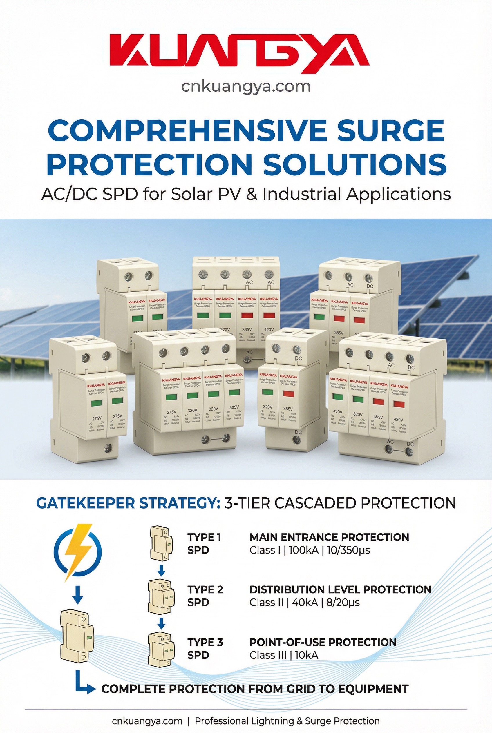
Чтобы должным образом защитить объект, необходимо перестать думать об одном сетевом фильтре и начать мыслить категориями скоординированной команды безопасности. Это Стратегия привратника. Представьте, что ваша электрическая система - это здание с высоким уровнем безопасности. У вас будет не просто один охранник на входе, а несколько уровней безопасности.

Основной привратник: СПД типа 1 на входе в здание
У главного входа в здание вам нужен грозный страж - вышибала, способный справиться с самыми серьезными угрозами. Это ваш Тип 1 СПД. Установленное на главном входе, это устройство является первой линией защиты от высокоэнергетических внешних перенапряжений, например, от прямых или близких ударов молнии. .
Вторичные привратники: СПД 2-го типа в филиалах
После главного входа на отдельных этажах или в особо важных помещениях все равно требуется охрана. Это ваши СПД типа 2, вторичные задвижки. Они устанавливаются на распределительных панелях и подпанелях, питающих критические нагрузки, и их роль принципиально иная. Они справляются с остатками энергии перенапряжения, пропущенной через SPD типа 1, а также с перенапряжениями, генерируемыми в пределах в помещении от такого оборудования, как двигатели и системы отопления, вентиляции и кондиционирования воздуха.
Такой многоуровневый подход, известный как “каскадирование” или “защита по глубине”, является краеугольным камнем эффективной защиты от перенапряжений. Один-единственный, слишком большой SPD на главной панели не сможет защитить от перенапряжений, возникающих внутри сети, и не сможет снизить напряжение до достаточно низкого уровня для чувствительной электроники, расположенной далеко внизу. Стратегия Gatekeeper обеспечивает управление угрозами в каждой критической точке системы.
Номинал кА (килоампер) - самая обсуждаемая и самая непонятная характеристика СПД. Многие полагают, что более высокий номинал кА автоматически означает лучшую защиту. Это опасное упрощение. Номинал кА определяет не только напряжение пропускной режим, защищающий ваше оборудование; он определяет SPD энергоемкость и срок службы. Это показатель того, насколько большой импульсный ток устройство может отвести на землю, и сколько раз оно может это сделать, прежде чем его компоненты выйдут из строя.
Сказка о двух формах волны: 10/350 мкс против 8/20 мкс
Разница между SPD типа 1 и типа 2, а значит, и требования к кА, заключаются в типе перенапряжения, на которое они рассчитаны. Они определяются стандартизированными формами испытательных сигналов.

Совет профессионала: Не увеличивайте размеры ради этого. Установка СПД с номиналом 400 кА на маленькой ответвительной панели - это не “лучшая” защита, а пустая трата денег. Главное - подобрать номинал и тип СПД в соответствии с его расположением в электрической системе. Как отмечает один эксперт, “больше - не всегда лучше. Нужно подбирать размер в соответствии с нагрузкой”. .
Правило “3-2-1”: Практическое руководство
На основе этой стратегии Gatekeeper появилось общепринятое эмпирическое правило для каскадных СПД, которое иногда называют “правилом 3-2-1”. .
Это правило представляет собой простую и надежную отправную точку для разработки многоуровневой системы защиты, которая правильно применяет рейтинги СПД KA в зависимости от их положения в качестве привратников.
Определение размера SPD не должно быть гаданием. Придерживаясь структурированного подхода, вы сможете обеспечить надлежащий уровень защиты каждого уровня вашей электрической системы. Вот практическая четырехэтапная схема реализации стратегии Gatekeeper.
Шаг 1: Определите положение цепи (главная или ответвление)
Это основополагающий шаг. Прежде чем изучать спецификацию СПД, определите, в каком месте электрической иерархии находится панель.
Шаг 2: Подберите SPD к номиналу главного автоматического выключателя
После определения позиции хорошей отправной точкой для определения необходимого номинала SPD kA является размер главного выключателя, питающего эту панель. Более мощный выключатель подразумевает большую мощность и потенциально больший доступный ток повреждения, что требует более надежного СПД.\
Хотя это и не идеальная наука, производители предоставляют таблицы, в которых размер выключателя соотносится с рекомендуемыми характеристиками SPD. Это гарантирует, что защитная способность SPD соответствует мощности цепи. .
Например, общее руководство может выглядеть следующим образом:
Совет профессионала: Эти значения являются отправной точкой. В местах повышенного риска, таких как Флорида или районы с нестабильной сетью, целесообразно выбирать номинал кА на более высоком конце рекомендуемого диапазона для данного размера выключателя. Это обеспечит более длительный срок службы, так как SPD будет подвергаться более частым импульсным перенапряжениям.
Шаг 3: Обеспечьте надлежащую координацию
Для работы стратегии Gatekeeper необходима координация. Восходящий (тип 1) SPD должен обладать достаточно высокой энергоемкостью, чтобы защитить нисходящий (тип 2) SPD. Если первичный привратник слишком слаб, большой скачок напряжения может его разрушить. и продолжайте уничтожать второстепенных стражей.
Правильная координация означает, что СПД типа 1 на входе обслуживания имеет значительно больший номинал кА, чем СПД типа 2 на подпанелях. Правило 3-2-1 - это форма предварительно рассчитанной координации. Кроме того, между устройствами типа 1 и типа 2 должно быть достаточное расстояние (обычно не менее 10 метров или 30 футов провода). Эта длина провода обеспечивает сопротивление, которое помогает двум устройствам эффективно работать вместе. Если это расстояние невозможно обеспечить, может потребоваться специальный гибридный SPD “Тип 1+2”, который специально разработан для координации в одном корпусе.
Шаг 4: Проверка уровня защиты по напряжению (Up / VPR)
После того как вы убедитесь, что СПД имеет нужный номинал кА, чтобы выжить Вы должны убедиться в том, что он имеет соответствующий рейтинг, чтобы защищать ваше оборудование. Это Рейтинг защиты по напряжению (VPR) или Уровень защиты по напряжению (вверх). Это значение в вольтах указывает на максимальное напряжение, которое SPD пропустит к защищаемому оборудованию.
Лучше меньше, да лучше.
Высокий номинал кА бесполезен, если проходное напряжение слишком велико для чувствительной электроники. Например, ПЛК или компьютер могут быть повреждены напряжением всего в несколько сотен вольт.
Распространенной ошибкой является ориентация исключительно на рейтинг KA SPD. Конечной целью является защита оборудования, а она определяется VPR. Хорошо подобранный СПД имеет как достаточный для его размещения номинал кА, так и достаточно низкий VPR для защищаемого им оборудования. .
Чтобы упростить выбор, в этих таблицах приведены основные различия и рекомендации в зависимости от стратегии Gatekeeper.
Таблица 1: Технические характеристики СПД для главных цепей (тип 1) и ответвлений (тип 2)
| Характеристика | Главный контур SPD (первичный шлюз) | Вторичная цепь SPD (вторичный шлюз) |
|---|---|---|
| Тип СПД | Тип 1 или Type 1+2 Hybrid | Тип 2 |
| Основная функция | Переживайте и отводите высокоэнергетические внешние импульсы | Ограничение остаточных и внутренних перенапряжений до безопасного уровня |
| Место установки | Сервисный вход, линия или нагрузка со стороны главного выключателя | Распределительные/разветвленные панели, сторона нагрузки выключателя |
| Форма тестовой волны | 10/350 мкс (имитирует прямую молнию) | 8/20 мкс (имитирует непрямое освещение/переключение) |
| Типичный номинал кА | 100 кА - 300 кА+ на фазу | 40 кА - 200 кА на фазу |
| Фокус | Высокое поглощение энергии (выживание) | Низкое проходное напряжение (Точность) |
| Технология | Часто MOV, GDT или надежный гибрид | Как правило, MOV или продвинутый гибрид |
Таблица 2: Рекомендуемое значение кА в зависимости от типоразмера выключателя (рекомендация)
Эта таблица представляет собой практическую отправную точку для подбора вторичного задвижного устройства (тип 2 SPD) к главному выключателю ответвительной панели. (Адаптировано из данных производителя).
| Номинал главного выключателя (амперы) | Рекомендуемый СПД кА | Типовое применение |
|---|---|---|
| 32A | 40 кА - 60 кА | Небольшая субпанель, цепи освещения |
| 63A - 100A | 80 кА - 120 кА | Стандартная ветка/распределительная панель |
| 200A | 100 кА - 160 кА | Большая субпанель, небольшой центр управления двигателем |
| 400A | 125 кА - 200 кА | Главная распределительная панель, панель критических нагрузок |
Таблица 3: Сравнение технологий компонентов (MOV против GDT против гибрида)
Внутренние компоненты определяют рабочие характеристики СПД.
| Компонент | Плюсы | Cons | Лучшее для |
|---|---|---|---|
| MOV (Металлооксидный варистор) | Быстрое время отклика, низкая стоимость, эффективное зажатие | Деградирует при каждом скачке напряжения, имеет ограниченный срок службы, при отсутствии защиты может произойти тепловой сбой | Применение типа 2 общего назначения, где стоимость является важным фактором |
| GDT (Газоотводная трубка) | Чрезвычайно высокая мощность импульсного тока, очень долгий срок службы, высокая изоляция | Более медленное время срабатывания по сравнению с MOV, более высокое начальное пропускное напряжение | Сверхмощные приложения типа 1, часто используются в сочетании с другими компонентами |
| Гибрид (MOV + GDT) | Лучшее из двух миров: GDT поглощает мощные импульсы, защищая MOV. MOV обеспечивает быстрое зажатие низкого уровня. | Более высокая стоимость, несколько более сложная конструкция | Высокопроизводительные приложения типа 1 и 2, где требуется максимальная защита и долговечность |
Номинальное значение кА в SPD напрямую зависит от технологии, используемой в нем. Две основные "рабочие лошадки" - это металлооксидный варистор (MOV) и газоразрядная трубка (GDT).

Металлооксидный варистор (MOV): Быстрый ответ
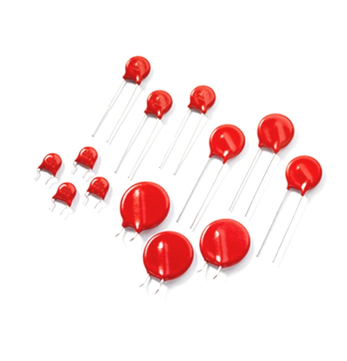
MOV - самый распространенный компонент в современных SPD. Это нелинейный резистор, который работает как невероятно быстрый переключатель. При нормальном напряжении он имеет очень высокое сопротивление и практически невидим для схемы. Когда напряжение поднимается выше порога срабатывания, его сопротивление падает почти до нуля за наносекунды, отводя вредный импульсный ток на землю. 4.
Газоразрядная трубка (ГРТ): Тяжелый удар

GDT - это простое и надежное устройство, обычно представляющее собой керамическую трубку, заполненную инертным газом. Два электрода разделены небольшим зазором. При нормальном напряжении газ является изолятором. Когда происходит скачок высокого напряжения, газ ионизируется, создавая проводящую дорожку (дугу), которая может шунтировать огромное количество тока на землю. .
Гибридные конструкции (GDT/MOV): Элитное решение
Учитывая сильные и слабые стороны каждого из них, в высокопроизводительных SPD часто используется гибридная конструкция, сочетающая GDT и MOV. В такой конфигурации GDT располагается перед MOV.
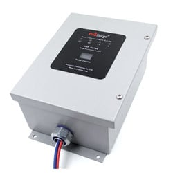
\
Типичный СПД типа 1 с высоким кА, внутри которого часто используется надежная гибридная технология.
Даже самая дорогая, идеально подобранная по размеру СПД может оказаться бесполезной из-за некачественной установки. Самым важным фактором является длина провода.
Устройство защиты от импульсных перенапряжений работает за счет отвода импульсного тока. Этот ток должен пройти от шины щита, через провода SPD, через сам SPD и к шине заземления. Каждый дюйм провода добавляет индуктивность, что создает падение напряжения. Во время быстро нарастающего импульсного перенапряжения это дополнительное напряжение от длинных, петляющих проводов может увеличить проходное напряжение на сотни вольт, сводя на нет защитные свойства SPD.
Ключевые моменты для правильной установки:
Вопрос 1: Всегда ли более высокий показатель кА СПД лучше?\
О: Не обязательно. Номинал кА должен соответствовать месту установки SPD. Массивный СПД на 300 кА на небольшой ветвистой панели - это излишество и нерентабельно. Важнее иметь скоординированная система правильно подобранных СПД на каждом уровне (главный и ответвление), чем иметь одно чрезмерно большое устройство.
Q2: Что важнее - номинал кА или номинал защиты по напряжению (VPR)?\
О: Они оба критичны, но по разным причинам. Сайт номинальный ток кА обеспечивает СПД возможность выжить энергия перенапряжения в месте его расположения. Сайт VPR гарантирует, что ваш оборудование сохранилось определяя, сколько напряжения проходит через него. SPD с высоким кА и высоким VPR выживет, но ваше оборудование может не выдержать. Сначала выберите номинал кА для выживания, а затем выберите самый низкий VPR, доступный для этого номинала, чтобы обеспечить максимальную защиту.
Q3: Могу ли я просто установить один большой SPD типа 1 на главной панели и на этом закончить?\
О: Это не рекомендуется. Хотя SPD типа 1 необходим для борьбы с большими внешними перенапряжениями, он не может защитить от перенапряжений, генерируемых внутри вашего объекта (от двигателей и т.д.). Кроме того, его VPR может быть недостаточно низким для защиты чувствительной электроники, расположенной вдали от панели. Многоуровневый, “каскадный” подход с устройствами типа 2, расположенными ниже по потоку, является единственным способом достижения комплексной защиты. .
Вопрос 4: Как узнать, когда нужно заменить СПД?\
О: Большинство современных SPD оснащены индикаторами состояния или флажками. Зеленый цвет обычно означает, что устройство активно и обеспечивает защиту. Если индикатор не горит, красный или звучит сигнал тревоги, это обычно означает, что защитные компоненты пожертвовали собой и устройство (или модуль в нем) нуждается в немедленной замене.
Вопрос 5: Защитит ли СПД от прямого удара молнии в мое здание?\
О: УЗД типа 1 предназначено для работы с импульсным током от поблизости или Коммунальная линия удара молнии. Однако ни один СПД не может обеспечить 100% защиту от прямого удара в саму конструкцию. СПД являются одним из компонентов полной системы молниезащиты (LPS), которая также включает в себя воздушные зажимы (молниеотводы) и заземляющие проводники, как определено в таких стандартах, как UL 96A.
