Промышленная зона Вэньян Юэцин Вэньчжоу 325000
Рабочие часы
Понедельник - пятница: 7AM - 7PM
Выходные: 10AM - 5PM
Промышленная зона Вэньян Юэцин Вэньчжоу 325000
Рабочие часы
Понедельник - пятница: 7AM - 7PM
Выходные: 10AM - 5PM
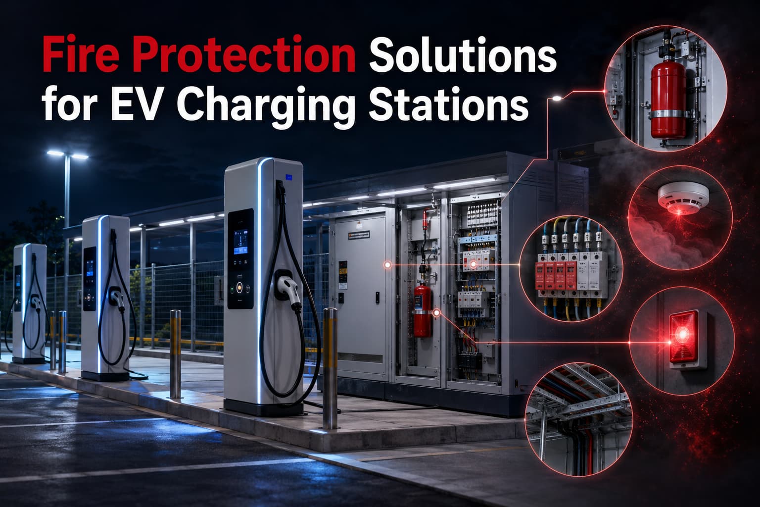
EV Charging Station Fire Protection is a critical requirement as electric vehicle (EV) charging infrastructure is expanding rapidly, especially in commercial parking lots, industrial parks, highway service areas, and residential complexes. At the same time, incidents of overheating, electrical faults, and charging cabinet fires are also increasing.
From an engineering perspective, most failures are not caused by a single component, but by a chain reaction across multiple weak points—power distribution, surge protection, cabling, and thermal management.
This article breaks down the real technical causes behind EV charging fires and the practical protection measures used in field installations, including SPD selection, fuse coordination, cable protection, and cabinet-level fire suppression strategies.
In real field cases, EV charger fire incidents are rarely “sudden.” They usually develop from long-term electrical stress.
Typical root causes include:
Loose crimping, poor torque control, or aging connectors can create micro-resistance points. Under high current (especially DC fast charging), local temperatures can exceed insulation limits.
Unlike AC systems, DC arcs do not naturally cross zero. Once an arc forms, it can sustain and escalate quickly.
Charging stations are often installed outdoors. Even indirect lightning strikes can introduce high transient overvoltage into the system.
Frequent bending, UV exposure, and thermal cycling degrade cable insulation over time, increasing leakage current risk.
Incorrect coordination between breaker, fuse, and SPD can cause delayed fault clearance.
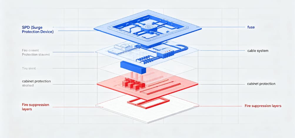
A common misunderstanding in EV charger safety design is relying on a single protective device.
In practice, protection must be layered:
| Protection Layer | Device / System | Функция |
|---|---|---|
| Защита от перенапряжения | SPD (Type 1 / Type 2) | Suppress lightning and switching surges |
| Защита от перегрузки по току | Fuse / MCB | Cut off short-circuit or overload current |
| Distribution Safety | Electrical cabinet design | Heat dissipation + isolation + wiring safety |
| Защита кабеля | EV charging cables | Thermal resistance + mechanical durability |
| Fire Control | Suppression system | Early-stage fire suppression |
Each layer addresses a different failure mode. Missing any one layer increases overall system risk significantly.
EV Charging Station Fire Protection requires proper SPD coordination at both AC and DC levels to reduce surge-related failures.
👉 You can view our EV charger surge protection solutions for more technical details:
SPD for photovoltaic and DC systems
EV charging stations are highly sensitive to surge damage, especially DC fast chargers.
EV Charging Station Fire Protection depends heavily on correct surge protection design. Surge protection design for EV charging systems should comply with international standards such as IEC 61643.
Many installations only place SPD at the AC side, ignoring internal DC side protection. This leads to:
In a Southeast Asia commercial charging station project (2024), repeated charger failures were traced to insufficient DC-side surge protection. After adding coordinated AC + DC SPD protection, failure rate dropped significantly within 3 months of operation.
In EV Charging Station Fire Protection design, fuse coordination is critical for isolating DC fault currents before thermal runaway occurs.
Fuses in EV charging systems are not just “overcurrent breakers.” In DC systems, their role is more critical because fault currents rise extremely fast.
Oversizing fuses “to avoid nuisance tripping” often leads to:
The fuse should protect the cable, not the load.
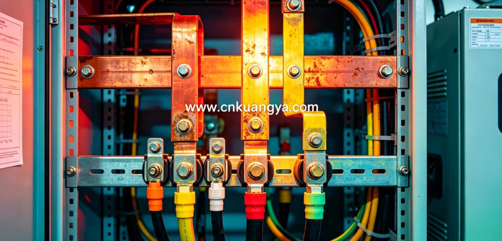
The EV charging cabinet is where most thermal and electrical risks concentrate.
Inside the cabinet, you typically find:
In many maintenance reports, thermal hotspots often appear at:
These are also the earliest ignition points in fire incidents.
Cables are often underestimated in EV charger fire protection design.
Field studies show that electrical faults and thermal stress are major contributors to EV charger failures.
Cable systems are often underestimated in EV charger fire protection design.
Once carbonization starts, the cable itself becomes a conductive path for fire propagation.
EV charging stations installed in open parking areas are exposed to indirect lightning surges.
Even if there is no direct strike, nearby lightning can induce:
At this stage, we have covered the main electrical and system-level causes behind EV charging station fire risks, including surge events, fuse coordination, cabinet overheating, and cable degradation.
In the next section, we will move into active protection strategies, including how fire suppression systems are integrated into EV charging cabinets and how early-stage detection can prevent thermal runaway escalation.
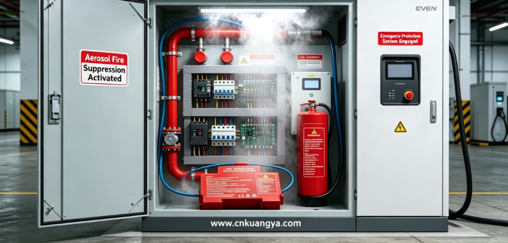
When electrical faults progress beyond the containment capacity of SPD, fuses, and breakers, the last line of defense becomes the fire suppression system inside the EV charging cabinet.
Unlike building-level fire protection, EV charger fires develop inside confined metal enclosures. This means:
So suppression must act early, locally, and without damaging electronics further.
| Тип системы | Principle | Application Suitability |
|---|---|---|
| Aerosol suppression | Chemical aerosol interrupts combustion chain reaction | Compact charging cabinets |
| Clean gas systems | Displace oxygen (e.g., inert gas) | Larger charging stations / battery rooms |
| Water mist systems | Cooling + oxygen reduction | Outdoor infrastructure (limited use inside cabinets) |
For EV charging cabinets, aerosol-based systems are widely used due to:
In multiple post-incident analyses of charging stations, fires often start in:
In several documented cases, suppression systems that activated within the first 30–60 seconds were able to:
SPD is not only a surge protection device—it is also indirectly a fire prevention component.
When SPD is undersized or improperly coordinated:
Installing SPD only based on “compliance checklist” rather than:
This leads to underprotected systems even if SPD is physically installed.
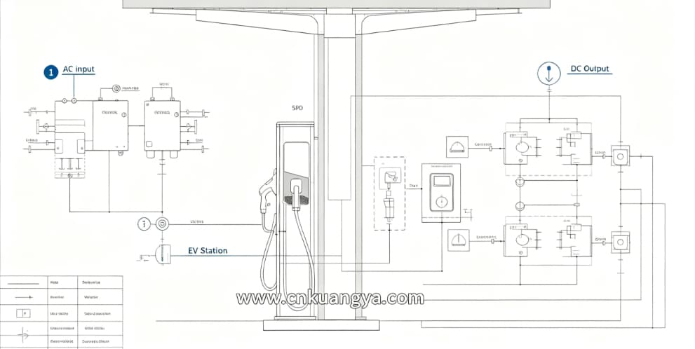
In professional EV charging infrastructure projects, protection is not device-based—it is system-based engineering design.
A typical integrated protection chain looks like this:
Electrical protection prevents fault escalation. Fire suppression prevents fault survival.
Both must work together.
Situation:
Investigation findings:
Corrective actions implemented:
Результат:
For field engineers and electricians, a practical checklist:
👉 A complete EV Charging Station Fire Protection strategy must integrate SPD, fuse coordination, cable protection, and cabinet-level fire suppression. Each layer plays a critical role in preventing electrical faults from escalating into fire incidents.
Because SPD only handles surge events. Most fires originate from thermal faults, loose connections, or DC arc faults, which SPD cannot stop alone.
Not always mandatory, but strongly recommended for:
Field reports show:
It can prevent fault escalation, but not all fire scenarios. Slow coordination or oversized fuses can still allow thermal damage before disconnection.
Treating protection as separate devices instead of a coordinated system (SPD + fuse + cable + thermal + suppression).
