웽양 공업구 웨칭 원저우 325000
근무 시간
월요일~금요일: 오전 7시~오후 7시
주말: 주말: 오전 10시 - 오후 5시
웽양 공업구 웨칭 원저우 325000
근무 시간
월요일~금요일: 오전 7시~오후 7시
주말: 주말: 오전 10시 - 오후 5시
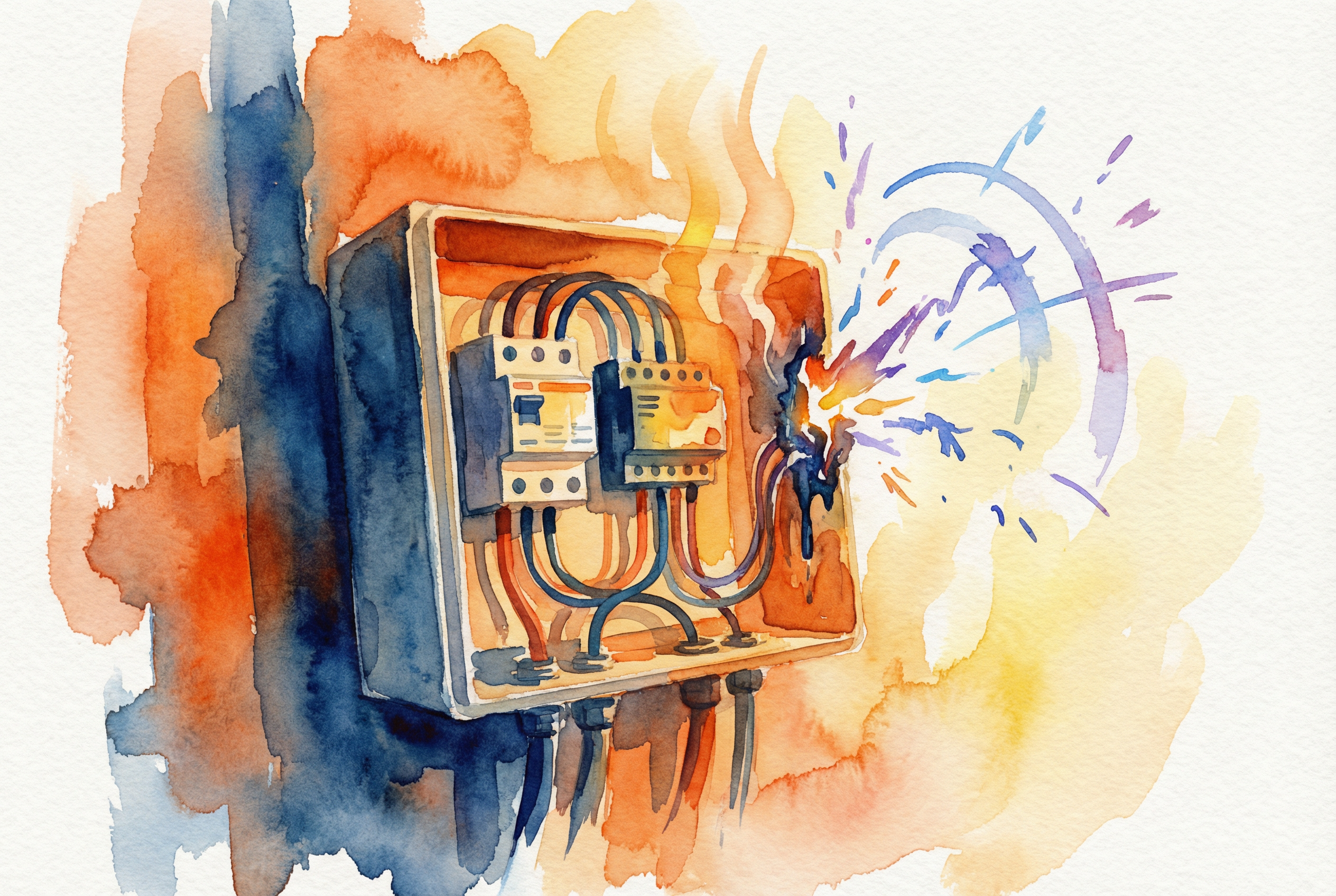
월요일 아침, 모든 전기 엔지니어가 두려워하는 전화가 걸려왔습니다. 불과 6개월 전에 시운전한 100kW 상업용 옥상 시스템이 고장 났다는 것이었습니다. 현장 관리자는 메인 DC 컴바이너 박스에서 “타는 플라스틱 냄새”가 난다고 설명했습니다. 현장에 도착했을 때 원인은 부품 결함이나 낙뢰가 아니었습니다. 컴바이너 박스 내부는 고급 DC 회로 차단기의 선과 부하 연결이 반대로 되어 있었기 때문에 검게 그을리고 녹아내린 엉망진창이었습니다.
전기 자동화 업계에서 15년 이상 선임 애플리케이션 엔지니어로 일하면서 수많은 시스템 장애를 분석해 왔습니다. 어려운 진실은 대부분의 치명적인 DC 측 문제는 값싼 장비로 인해 발생하는 것이 아니라 다음과 같은 원인으로 인해 발생한다는 것입니다. DC 보호 배선 실수.
제로 크로싱 특성으로 인해 관대한 교류(AC)와 달리 직류(DC)는 가차없이 흐릅니다. 잘못 다루면 몇 밀리초 만에 화재 위험으로 이어질 수 있는 지속적인 에너지 흐름입니다. 이 가이드는 현장에서 어렵게 얻은 교훈에서 탄생했습니다. 현장에서 흔히 볼 수 있는 10가지 실수를 살펴보고 이를 방지하는 데 필요한 실행 가능한 엔지니어링 프레임워크를 제공합니다.
이는 의심할 여지 없이 DC 설치에서 가장 빈번하고 위험한 오류입니다.
문제:
교류 회로에서는 전류가 1초에 100회 또는 120회 방향을 바꿉니다. DC 회로에서는 전류가 한 방향으로 흐릅니다. 많은 고성능 DC 회로 차단기는 “분극형”입니다. 여기에는 전기 아크를 밀어내도록 설계된 영구 자석이 포함되어 있습니다. 에 차단기가 작동하면 아크 소화용 슈트가 작동합니다.
이를 거꾸로 배선하면(라인과 부하를 바꾸면) 내부 자기장이 아크를 당깁니다. away 를 슈트에서 차단기의 섬세한 기계 부품으로 전달합니다. 아크는 꺼지지 않고 지속되어 차단기를 녹이고 인클로저를 점화할 수 있습니다.
솔루션:
+ 및 - 기호 또는 LINE 및 로드 표시가 있습니다.![이미지: 극성(+/-) 및 라인/부하 표시가 명확하게 표시된 DC 회로 차단기 클로즈업][이미지: 극성(+/-) 및 라인/부하 표시]
핵심 사항: 극성 DC 차단기의 경우 올바른 극성은 권장 사항이 아니라 아크 소호의 물리학이 작동하기 위한 필수 요건입니다. 전원을 공급하기 전에 항상 멀티미터로 다시 확인하세요.
안전한 연결은 안전한 연결입니다. 안타깝게도 손으로 조이는 “굿 앤 타이트” 방식은 열 고장의 원인이 될 수 있습니다.
문제:
솔루션:
토크를 가하지 않은 연결에 대해 “무관용” 정책을 적용합니다. 반드시 보정된 토크 드라이버를 사용해야 합니다.
전문가 팁: “표시 후 이동” 방법
제조업체에서 지정한 토크(일반적으로 차단기 측면에 N-m 또는 lb-in 단위로 인쇄되어 있음)를 가한 후 나사와 하우징에 “토크 씰” 또는 검사자용 래커를 도포합니다. 이렇게 하면 작업이 완료되었음을 시각적으로 증명할 수 있고 향후 검사 시 나사가 느슨하게 진동했는지 쉽게 확인할 수 있습니다.
![이미지: DC 단자에 보정된 노란색 토크 드라이버를 사용하여 토크 씰 페인트를 도포하는 기술자][이미지: 보정된 노란색 토크 드라이버를 사용하는 기술자
DC 회로에서 AC 차단기를 사용하는 것은 자전거 브레이크로 폭주하는 화물 열차를 멈추려고 하는 것과 같습니다.
문제:
AC 전력은 자연적으로 초당 100회 이상 0볼트를 교차합니다. AC 차단기는 이 “제로 크로싱”에 의존하여 아크를 소멸시킵니다. DC에는 제로 크로싱이 없습니다. 600V DC 스트링에 AC 차단기를 사용하면 차단기가 열릴 수 있지만 아크가 접점을 연결하여 장치가 파괴될 때까지 계속 연소됩니다.
표 1: AC 대 DC 회로 차단기 사양
| 기능 | 표준 AC 회로 차단기 | DC 정격 회로 차단기 | DC 보호가 중요한 이유 |
|---|---|---|---|
| 아크 담금질 | 제로 크로싱 의존도 | 마그네틱 블로우아웃 및 아크 슈트 | DC 아크는 연속적이므로 물리적으로 늘리고 냉각시켜야 멈출 수 있습니다. |
| Gap에 문의 | 더 작게 | 훨씬 더 크게 | DC 아크를 차단하려면 더 큰 간격이 필요합니다. |
| 편광 | 비편광 | 종종 양극화 | 방향성 자석이 아크를 슈트로 안내합니다. |
| 인터럽트 등급 | AC 암페어 정격 | 정격 DC 암페어 | AC 등급은 다음과 같습니다. 유효하지 않음 DC 애플리케이션용입니다. |
솔루션:
차단기의 물리적 적합성(예: DIN 레일 장착)에만 의존하지 마세요. 항상 데이터시트에 명시적으로 명시되어 있는 DC 전압 정격 및 DC 인터럽트 용량.
DC 보호 사이징은 단순히 전선 용량을 맞추는 것만이 아니라 “125% 규칙'을 준수하고 연속적인 듀티를 고려해야 합니다.
문제:
NEC 690.8조에서는 태양광 회로 전류를 “연속”으로 간주하도록 규정하고 있습니다. 즉, 도체와 과전류 보호 장치(OCPD)의 크기는 계산된 최대 회로 전류의 125%에 맞춰야 합니다. 단락 전류(Isc)가 10A인 스트링의 경우 10A 퓨즈를 사용할 수 없습니다. 결국 열 스트레스로 인한 피로와 성가신 트립이 발생할 수 있습니다.
솔루션:
이 3단계 선택 방법을 따르세요:
표 2: gPV 퓨즈 사이징 계산 예제
| 매개변수 | 가치 | 계산 / 논리 |
|---|---|---|
| 모듈 Isc | 12A | 태양광 패널 데이터시트에서 |
| 안전 계수 | 1.25 | NEC 연속 근무 요건 |
| 최소 퓨즈 등급 | 15A | $12A \배수 1.25 = 15A$ |
| 주변 온도 감소 | 0.90 | 박스 내부 온도 50°C 가정 |
| 최종 퓨즈 선택 | 20A | 0.90으로 감전된 15A 퓨즈는 13.5A에 불과합니다(Isc에 너무 근접). 성가신 끊김을 방지하려면 20A로 크기를 늘리세요. |
서지 보호 장치(SPD)는 매우 중요하지만 그 효과는 물리학, 특히 인덕턴스에 의해 결정됩니다.
문제:
전선의 인덕턴스는 전류의 변화에 저항합니다. 번개는 전류에 엄청난 순간적인 변화를 일으킵니다($di/dt$). $V = L \times (di/dt)$ 공식에 따르면, 짧은 길이의 전선($L$)도 서지 중에 엄청난 전압 강하($V$)를 일으킵니다. SPD 리드가 길고 코일형인 경우 전압 스파이크가 SPD를 우회하여 인버터로 바로 전달되므로 보호 기능이 무용지물이 됩니다.
솔루션:
리드 유지 짧고 곧게. 90도로 급격하게 구부리지 마세요.
머메이드 다이어그램 1: 올바른 SPD 배선 대 잘못된 배선
핵심 사항: 전선의 1센티미터마다 인덕턴스가 추가됩니다. 1미터의 전선으로 SPD를 연결하면 급격한 서지 이벤트가 발생하는 동안 효과적으로 연결을 끊을 수 있습니다.
옥상에 표준 건물 전선(THHN)을 사용하는 것은 시한폭탄을 안고 있는 것과 같습니다.
문제:
태양광 어레이의 DC 케이블은 극심한 자외선, 온도 변화(동결에서 고온까지), 습기에 노출됩니다. 표준 PVC 절연은 몇 년 동안 자외선에 노출되면 균열이 생기고 벗겨져 위험한 접지 결함 및 잠재적인 아크 섬광이 발생할 수 있습니다.
솔루션:
![이미지: 전선이 처지지 않고 금속 클립을 사용하여 랙에 고정되어 깔끔한 케이블 관리를 보여주는 전문 태양광 설치 사례]
연결 해제와 관련된 규정 준수는 주로 응급 구조대원의 안전에 관한 것입니다.
문제:
NEC 690.13은 “쉽게 접근할 수 있는” 분리를 요구합니다. 드라이버로 열어야 하는 잠긴 컴바이너 박스 안에 차단기를 숨기거나 휴대용 사다리로 접근해야 하는 지붕 위에 놓는 것은 이 규칙에 위배됩니다. 소방관이 스위치를 찾지 못하거나 안전하게 접근할 수 없는 경우 시스템의 전원을 차단할 수 없습니다.
솔루션:
25°C에서 20A 정격 퓨즈는 60°C에서 20A를 유지하지 못합니다.
문제:
옥상에 있는 컴바이너 박스는 오븐으로 변합니다. 내부 온도는 쉽게 60°C(140°F)를 초과할 수 있습니다. 온도가 상승하면 퓨즈 또는 열 자기 차단기 내부의 금속 소자가 연화되어 정격보다 낮은 전류에서 차단기가 트립될 수 있습니다. 이로 인해 태양광 생산량이 가장 높아야 할 더운 날에 시스템이 종료되는 “팬텀 트립'이 발생합니다.
표 3: 일반적인 케이블 전류 용량 감소 계수(90°C 정격 전선)
| 주변 온도(°C) | 주변 온도(°F) | 보정 계수 | 40A 케이블에 미치는 영향 |
|---|---|---|---|
| 36-40 | 97-104 | 0.91 | 36.4A |
| 46-50 | 114-122 | 0.82 | 32.8A |
| 56-60 | 132-140 | 0.71 | 28.4A |
| 66-70 | 151-158 | 0.58 | 23.2A |
솔루션:
항상 제조업체의 데이터시트 또는 NEC 표 310.15(B)(2)(a)의 온도 보정 계수를 적용하세요. 상자가 햇볕에 노출되어 있는 경우 내부 온도를 주변 온도 + 15°C 이상으로 가정하세요.
오류가 발생하면 오류와 가장 가까운 장치만 트리거되어야 합니다. 이를 “선택성”이라고 합니다.”
문제:
스트링 레벨에 15A 퓨즈가 있고 컴바이너 출력에 20A 차단기가 있는 경우, 한 스트링에서 오류가 발생하면 스트링 퓨즈가 끊어지는 대신 주 차단기가 트립될 수 있습니다. 그러면 하나의 스트링이 아닌 전체 어레이가 중단됩니다.
솔루션:
업스트림 장치와 다운스트림 장치 사이에 충분한 비율이 있는지 확인합니다. 시간-전류 곡선(TCC)을 사용하여 업스트림 디바이스가 고정을 해제하기 전에 다운스트림 디바이스가 고정을 해제하는지 확인합니다.
표 4: 다양한 장애 조건에 대한 보호 방법
| 결함 유형 | 특성 | 권장 장치 | 응답 시간 |
|---|---|---|---|
| 과부하 | 101-200% 전류(느린 상승) | 열-자기 DC 차단기 | 초에서 분으로 |
| 단락 회로 | 10~20배 전류(순간 스파이크) | gPV 퓨즈 또는 자기 차단기 | <10ms |
| 접지 오류 | 접지로 누설되는 전류 | GFDI/RCD | <100ms |
DC라고 해서 폭발하지 않는다는 의미는 아닙니다.
문제:
직류 아크는 교류 아크보다 더 뜨겁고 오래 지속됩니다. 대형 배터리 뱅크 또는 1500V 태양광 결합기의 아크 플래시는 20,000°C를 초과하는 온도를 방출할 수 있습니다. 엔지니어는 종종 AC 스위치기어에 대한 아크 플래시 경계를 계산하지만 DC 쪽은 무시합니다.
솔루션:
![이미지: 적절한 아크 플래시 PPE를 착용한 기술자가 상용 DC 컴바이너 박스에서 작업하고 있는 모습]
시스템이 안전하고 보험에 가입할 수 있도록 하려면 올바른 표준 인증을 받은 구성 요소를 사용해야 합니다. 유럽 IEC 프로젝트에서 UL 구성 요소를 사용하거나 그 반대의 경우 제대로 상호 참조하지 않으면 검사 실패로 이어질 수 있습니다.
표 5: IEC와 UL 인증 표준 비교
| 사양 | IEC 60269-6(글로벌) | UL 2579(북미) |
|---|---|---|
| 범위 | 태양광 전용 퓨즈(gPV) | 태양광 시스템용 퓨즈 |
| 시간 상수 | 5ms ~ 15ms | 5ms ~ 12ms |
| 전압 등급 | 600V, 1000V, 1500V DC | 300V, 600V, 1000V, 1500V DC |
| 차단 용량 | 10kA, 20kA, 30kA | 10kA, 15kA, 20kA, 30kA |
| 테스트 접근 방식 | 성능 매개변수 | 시스템 수준 안전 및 NEC 정렬 |
Q: 표준 AC 퓨즈를 사용할 수 있나요? 태양광 결합기 박스?
A: 절대 아닙니다. AC 퓨즈는 DC 아크를 차단하도록 설계되지 않았습니다. AC 퓨즈를 사용하면 심각한 화재 위험이 있습니다. 항상 “gPV” 등급 또는 UL 2579 목록을 확인하세요.
Q: 더운 오후에 DC 차단기가 계속 트립되는 이유는 무엇인가요?
A: 이는 열 경감 때문일 수 있습니다. 인클로저 내부의 주변 온도가 높으면 차단기의 열 소자가 팽창하여 트립 임계값이 낮아집니다. 크기 계산을 확인하고 올바른 온도 보정 계수를 적용하세요.
Q: 토크 드라이버가 꼭 필요한가요? 손이 교정된 느낌입니다.
A: 네, 필요합니다. 토크에 대한 인간의 인식은 부정확한 것으로 악명이 높습니다. 과소 토크는 열과 화재로 이어지고, 과대 토크는 기계적 파손으로 이어집니다. 시스템 안전을 위한 작은 투자입니다.
질문: 부하 차단과 비부하 차단 연결 해제의 차이점은 무엇인가요?
A: 부하 차단 차단기는 전체 전류를 안전하게 차단하도록 설계되었습니다. 비부하 차단 차단기(아이솔레이터)는 인버터 등으로 전류가 차단된 후에만 열어야 합니다. 부하 상태에서 무부하 차단 스위치를 열면 위험한 아크가 발생합니다.
직류 보호 시스템을 올바르게 배선하는 것은 직류의 물리학을 존중하는 것입니다. 단순히 전선을 연결하는 것 이상의 극성, 온도, 인덕턴스 및 아크 동작에 대한 깊은 이해가 필요합니다.
이러한 10가지 일반적인 실수를 피하는 것은 단순히 점검 양식의 체크 박스에 체크하는 것이 아니라 투자의 수명과 이를 유지 관리하는 사람들의 안전을 보장하는 것입니다.
