웽양 공업구 웨칭 원저우 325000
근무 시간
월요일~금요일: 오전 7시~오후 7시
주말: 주말: 오전 10시 - 오후 5시
웽양 공업구 웨칭 원저우 325000
근무 시간
월요일~금요일: 오전 7시~오후 7시
주말: 주말: 오전 10시 - 오후 5시

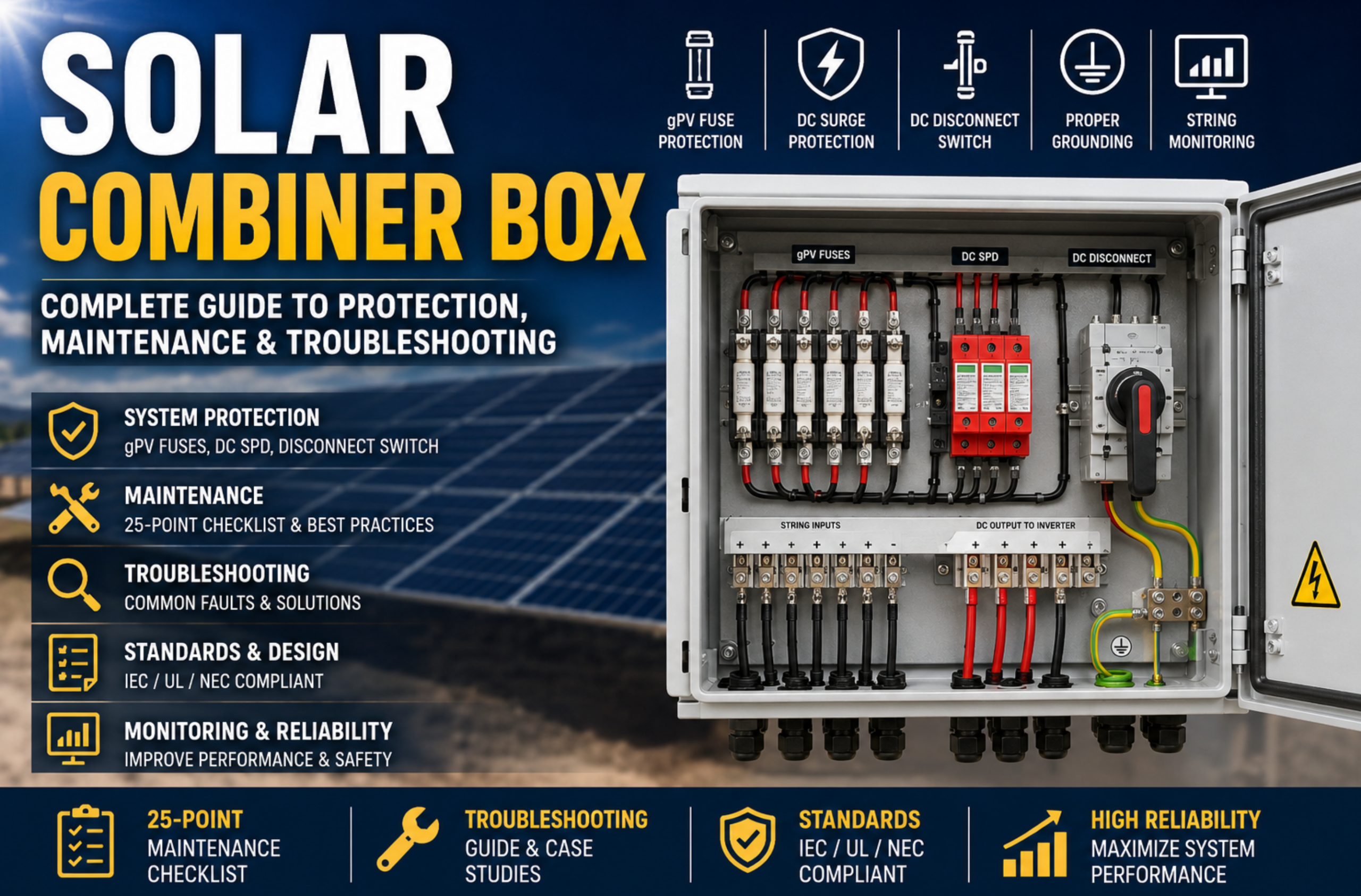
A solar combiner box is much more than a junction enclosure. It is the primary DC protection center of a photovoltaic (PV) system, combining multiple PV strings while integrating protective devices such as gPV fuses, DC surge protective devices (SPDs), disconnect switches, monitoring modules, and grounding systems.
A properly designed combiner box improves safety, simplifies maintenance, reduces inverter failures, and minimizes downtime. Poor design or inadequate maintenance, however, can lead to overheating, DC arc faults, insulation damage, production losses, and, in severe cases, electrical fires.
PV Combiner Box Guide 2025 | Safe & Reliable HS/HD Models Kuangya
This engineering guide explains:
Whether you are an EPC contractor, electrical engineer, PV installer, or operations and maintenance specialist, understanding the combiner box is essential for building safer and more reliable solar power systems.
PV Combiner Box Guide 2025 | Safe & Reliable HS/HD Models Kuangya
A solar combiner box is an electrical enclosure that combines multiple photovoltaic strings into a single DC output before the electricity reaches the inverter.
Instead of running dozens of individual cables directly to an inverter, each PV string is first connected to the combiner box. Inside the enclosure, current from multiple strings is combined while several protection devices continuously safeguard the circuit.
Modern combiner boxes usually contain:
Although it appears to be a simple enclosure, the combiner box performs several critical engineering functions simultaneously.
It protects the DC circuit against overcurrent, reverse current, transient overvoltage, insulation deterioration, and maintenance hazards while simplifying troubleshooting and reducing installation complexity.
As PV systems continue increasing from hundreds of volts to 1000V DC and 1500V DC architectures, the importance of proper combiner box design has become significantly greater.
Small residential systems with only one or two strings may connect directly to the inverter.
Commercial rooftops and utility-scale solar farms are entirely different.
Large projects commonly contain:
Without a combiner box, every string would require an individual cable running to the inverter.
That approach creates:
A combiner box solves these problems by providing one centralized collection point.
Instead of troubleshooting thirty independent string circuits at the inverter, technicians can inspect all protection devices inside one enclosure.
This greatly reduces maintenance time.
For EPC contractors, combiner boxes also simplify commissioning because every string can be tested individually before energizing the inverter.
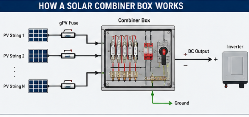
The operating principle is straightforward but extremely important.
Each photovoltaic string generates DC electricity.
These strings enter the combiner box through individual cable glands.
Inside the enclosure, each string usually passes through its own gPV fuse.
After fuse protection, multiple strings are connected together using DC busbars.
A surge protective device is connected between the DC conductors and earth.
The combined output then passes through a DC disconnect switch before leaving the combiner box and continuing toward the inverter.
During normal operation:
PV Modules
↓
String Cable
↓
gPV 퓨즈
↓
버스 바
↓
DC SPD
↓
연결 해제 스위치
↓
DC Output
↓
인버터
Although this process appears simple, every component plays a different role in electrical protection.
The overall reliability of the system depends on proper coordination among these devices.
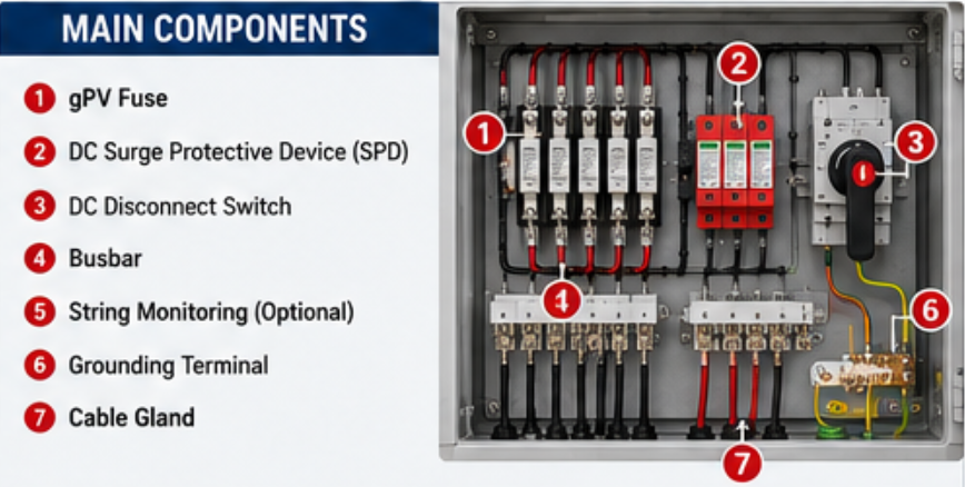
The gPV fuse protects each individual string from reverse current and overcurrent conditions.
When multiple strings operate in parallel, a faulted string may receive reverse current from healthy strings.
Without fuse protection, excessive current can overheat cables, damage modules, and create fire hazards.
The fuse interrupts abnormal current before severe damage occurs.
Proper fuse selection should consider:
Selecting an incorrect fuse is one of the most common engineering mistakes.
Lightning does not need to strike the solar array directly.
Nearby lightning can induce transient overvoltages inside long DC cables.
Switching operations can also generate voltage spikes.
A DC SPD limits these transient voltages before they damage the inverter or monitoring electronics.
Modern utility-scale systems generally install Type 2 DC SPDs inside combiner boxes.
In areas with high lightning density, additional protection coordination may be required.
Maintenance personnel must isolate equipment safely.
The disconnect switch provides visible electrical isolation before maintenance begins.
Unlike AC circuits, interrupting DC current is considerably more challenging because the current does not naturally cross zero.
Therefore, disconnect switches must be specifically designed for photovoltaic DC applications.
Busbars combine current from multiple strings into one output conductor.
Poor busbar design increases resistance.
Higher resistance creates heat.
Heat accelerates insulation aging.
Eventually overheating may loosen terminals and increase fire risk.
Good busbar design reduces power loss while improving long-term reliability.
Many modern combiner boxes include intelligent monitoring.
Typical parameters include:
Monitoring allows maintenance teams to identify abnormal conditions before production losses become significant.
A properly engineered PV system uses multiple protection layers.
Instead of relying on one protective device, engineers combine several technologies that complement one another.
Typical architecture:
PV Module
↓
DC Cable
↓
gPV 퓨즈
↓
DC 버스바
↓
DC SPD
↓
연결 해제 스위치
↓
Combiner Output
↓
인버터
↓
AC SPD
↓
트랜스포머
↓
Grid
Each layer addresses a different electrical risk.
예를 들어
The fuse interrupts abnormal current.
The SPD limits surge voltage.
The disconnect switch isolates equipment.
The inverter monitors operating conditions.
Together they provide coordinated protection.
One of the largest misconceptions is believing that a combiner box simply combines cables.
In reality it improves reliability in several ways.
Technicians can isolate one string without shutting down the entire plant.
Maintenance becomes significantly easier.
Downtime decreases.
Protection devices work together.
A correctly coordinated system minimizes unnecessary outages while ensuring dangerous faults are cleared rapidly.
Instead of dozens of individual cables running across the site, current is consolidated efficiently.
Cable management becomes cleaner.
Voltage drop can also be optimized.
Every protective device is located inside one enclosure.
Routine inspection becomes much faster.
Thermal imaging can identify loose terminals before failures occur.
Maintenance costs decrease over the lifetime of the project.
Combiner boxes reduce the likelihood of exposed energized conductors during maintenance.
Integrated disconnect switches allow technicians to isolate circuits safely before servicing downstream equipment.
When properly designed, they also reduce the probability of DC arc propagation within the collection system.
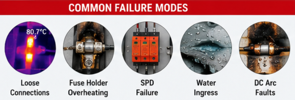
Even the highest-quality combiner box cannot guarantee reliable operation if it is improperly designed, incorrectly installed, or poorly maintained. In field applications, most failures develop gradually rather than occurring suddenly.
Understanding how these failures occur enables engineers to identify early warning signs, improve maintenance planning, and reduce unexpected downtime.
The following are among the most common failure modes observed in commercial and utility-scale photovoltaic systems.
Loose electrical terminals remain one of the leading causes of combiner box failures.
PV systems operate outdoors under continuous thermal cycling. During the day, conductors expand as temperatures rise. At night, they contract as temperatures fall. Over thousands of heating and cooling cycles, improperly tightened terminals can gradually loosen.
Even a slight increase in contact resistance generates additional heat. Because electrical power loss is proportional to the square of the current (I²R), a small increase in resistance can rapidly produce significant temperature rise.
Typical warning signs include:
Loose terminals are usually preventable through correct installation torque and periodic inspection.
Many engineers assume that fuse failures are caused only by excessive current.
In reality, poor contact inside the fuse holder is a much more common problem.
A low-quality fuse holder, contaminated contact surface, or worn spring mechanism increases electrical resistance.
Instead of interrupting fault current, the fuse holder itself becomes the source of excessive heat.
Long-term overheating accelerates insulation aging and may eventually ignite nearby plastic components.
For this reason, fuse holders should always be inspected together with the fuse links.
Unlike circuit breakers or disconnect switches, surge protective devices gradually wear out.
Every lightning event or switching transient slightly degrades the internal MOV elements.
Eventually the SPD reaches the end of its service life.
Most modern DC SPDs include a visual status indicator.
Engineers should inspect these indicators during routine maintenance and replace failed modules immediately.
Ignoring a failed SPD leaves the inverter vulnerable to future surge events.
Outdoor combiner boxes operate under rain, condensation, humidity, and large temperature variations.
Although the enclosure may be rated IP65 or higher, improper cable glands, damaged seals, or poor installation practices often allow moisture to enter.
Moisture creates several problems simultaneously:
In coastal environments, salt contamination further increases corrosion rates.
Regular inspection of seals and cable glands is therefore essential.
Solar installations are exposed to ultraviolet radiation every day.
Plastic cable ties, cable insulation, gland materials, warning labels, and enclosure gaskets all degrade over time.
Small surface cracks gradually become water entry points.
UV-resistant materials should always be specified for outdoor photovoltaic installations.
One of the most dangerous failure modes is the DC arc fault.
Unlike AC current, direct current does not naturally pass through zero.
Once an electrical arc forms, it can continue burning until sufficient separation or interruption occurs.
일반적인 원인은 다음과 같습니다:
An undetected arc fault may eventually carbonize insulation and ignite combustible materials inside the enclosure.
This is why layered protection—including correctly selected gPV fuses, DC SPDs, disconnect switches, and where appropriate, cabinet fire suppression—should be considered during system design.
Not every component failure results from poor manufacturing.
Many failures originate during system design.
예를 들면 다음과 같습니다:
Protection devices should always be coordinated as one complete protection system rather than selected independently.
A high-quality combiner box begins long before manufacturing.
Its reliability is determined during engineering design.
The following design principles are widely adopted in utility-scale photovoltaic projects.
Photovoltaic systems operate under continuous DC voltage.
Components designed only for AC applications should never be substituted.
Every protection device—including fuses, disconnect switches, and surge protective devices—should be specifically certified for photovoltaic DC systems.
Long conductors increase resistance, create additional voltage drop, and reduce surge protection performance.
The internal layout should keep conductor routing as short and direct as possible.
This also improves maintenance accessibility.
As system voltage increases to 1000V DC and 1500V DC, insulation spacing becomes increasingly important.
Adequate creepage and clearance distances reduce the probability of flashover under humid or contaminated conditions.
Combiner boxes are frequently installed in direct sunlight.
Engineers should consider:
Lower operating temperature significantly extends equipment life.
Maintenance begins during design.
A properly designed combiner box should provide:
The easier the maintenance, the lower the lifetime operating cost.
One of the biggest mistakes in PV engineering is expecting one protective device to solve every electrical problem.
Each device has a different purpose.
| 장치 | 주요 기능 |
|---|---|
| gPV 퓨즈 | Overcurrent and reverse-current protection |
| DC SPD | Transient overvoltage protection |
| DC 차단 스위치 | Safe electrical isolation |
| 모니터링 시스템 | Fault detection and diagnostics |
| Fire Protection Device | Early suppression of cabinet fires |
When these devices are coordinated correctly, they reduce equipment stress, improve reliability, and minimize system downtime.
A combiner box should therefore be viewed as an integrated protection platform rather than simply a cable junction enclosure.
Preventive maintenance is one of the most cost-effective ways to improve PV system reliability. A structured inspection program helps identify minor issues before they develop into equipment failures or production losses.
The following checklist can be used during commissioning, scheduled maintenance, or troubleshooting.
✓ Check the enclosure for cracks, deformation, or impact damage.
✓ Verify that the door closes securely and that locking mechanisms operate correctly.
✓ Inspect all cable glands for tightness and signs of deterioration.
✓ Confirm that the enclosure seals remain intact and maintain the required IP rating.
✓ Check mounting brackets and fasteners for corrosion or looseness.
✓ Verify terminal torque according to the manufacturer’s specifications.
✓ Inspect busbars for discoloration or evidence of overheating.
✓ Examine conductor insulation for cuts, abrasion, or UV damage.
✓ Ensure grounding conductors are secure and continuous.
✓ Confirm that wiring labels remain legible.
✓ Inspect every gPV fuse for damage or discoloration.
✓ Check fuse holders for signs of overheating.
✓ Verify the operating status of all DC SPDs.
✓ Test the DC disconnect switch for smooth operation.
✓ Replace any damaged or expired protection components immediately.
✓ Perform infrared thermal imaging during normal operating conditions.
✓ Compare temperatures between identical string connections.
✓ Investigate any hotspot that exceeds normal operating temperature.
✓ Record temperature trends for future comparison.
✓ Schedule corrective action where abnormal heating is detected.
✓ Record inspection dates.
✓ Document replaced components.
✓ Photograph abnormal conditions.
✓ Update maintenance history.
✓ Schedule follow-up inspections if required.
A consistent maintenance routine significantly reduces the likelihood of unexpected failures and extends the service life of both the combiner box and downstream equipment.
Even with proper maintenance, faults can still occur. The table below provides a practical troubleshooting reference for field engineers.
| 증상 | 가능한 원인 | 권장 조치 |
|---|---|---|
| One PV string produces lower current | Blown gPV fuse, loose connector, damaged module | Inspect the fuse, verify connector integrity, test the string |
| Combiner box temperature is unusually high | Loose terminals, overloaded conductors, poor ventilation | Tighten terminals, verify conductor sizing, improve ventilation |
| SPD status indicator shows failure | End-of-life MOV after repeated surge events | Replace the SPD module immediately |
| Inverter reports insulation fault | Moisture ingress, damaged cable insulation | Measure insulation resistance and inspect cable routing |
| DC disconnect switch is difficult to operate | Mechanical wear or contamination | Inspect, clean, or replace the switch |
| Visible burn marks inside the enclosure | Loose connections or sustained DC arcing | Isolate the circuit immediately and replace damaged components |
The objective of troubleshooting is not only to restore operation but also to identify and eliminate the root cause to prevent recurrence.
During routine thermal inspection, maintenance personnel identified a fuse holder operating at approximately 40°C higher than adjacent circuits.
The root cause was an improperly tightened terminal introduced during installation. The connection was corrected before insulation damage occurred, avoiding a potential outage affecting multiple PV strings.
Routine thermal imaging can detect abnormal resistance long before visible damage appears.
A rooftop PV system experienced repeated inverter alarms during thunderstorms.
Inspection revealed that the DC SPD modules had reached the end of their service life after several years of operation. Replacing the SPD modules restored surge protection and eliminated recurring alarms.
SPDs are sacrificial devices and should be inspected periodically rather than assumed to last for the entire life of the PV system.
A combiner box installed near the coast developed internal corrosion despite the enclosure remaining mechanically intact.
The investigation found improperly sealed cable glands that allowed moisture and salt-laden air to enter.
After replacing the seals and damaged terminals, no further insulation-related alarms were reported.
Environmental conditions should always be considered during component selection and installation.
A solar combiner box combines multiple PV strings into a single protected DC output while providing overcurrent protection, surge protection, isolation, and monitoring.
Small residential systems may not require one. Commercial and utility-scale systems almost always benefit from centralized DC protection.
A visual inspection is commonly performed every 6 to 12 months, while thermal imaging is recommended annually or after major weather events, depending on operating conditions.
A combiner box alone cannot prevent lightning damage. However, correctly coordinated DC surge protective devices significantly reduce transient overvoltage reaching sensitive equipment.
They protect individual PV strings from reverse current and overcurrent faults, reducing the likelihood of cable overheating and equipment damage.
No. The disconnect switch provides safe electrical isolation, while the fuse protects against abnormal current conditions. Both devices perform different functions.
Common warning signs include excessive heat, discoloration, damaged insulation, repeated inverter alarms, failed SPD indicators, moisture ingress, and abnormal string current.
Yes. Infrared inspection is one of the most effective methods for identifying loose connections, overloaded conductors, and abnormal heating before failures occur.
The solar combiner box is one of the most critical components in a photovoltaic system. It is not simply a junction enclosure but an integrated protection platform that combines overcurrent protection, surge protection, electrical isolation, monitoring, and maintenance accessibility.
A well-engineered combiner box improves system safety, simplifies maintenance, reduces downtime, and extends the service life of inverters and other downstream equipment.
The most reliable PV systems do not depend on a single protective device. Instead, they use a coordinated protection strategy that combines correctly selected gPV fuses, DC surge protective devices, disconnect switches, robust grounding, regular maintenance, and, where appropriate, cabinet fire protection.
For EPC contractors, installers, and system owners, investing in proper combiner box design and preventive maintenance is one of the most effective ways to reduce lifecycle costs and improve long-term system performance.
If you are designing or upgrading a photovoltaic project, selecting high-quality DC protection components and implementing a structured maintenance program will help ensure safer, more reliable, and more efficient solar power generation for years to come.
Selecting the right combiner box depends on much more than the number of PV strings. System voltage, maintenance strategy, environmental conditions, monitoring requirements, and long-term operating costs all influence the final design.
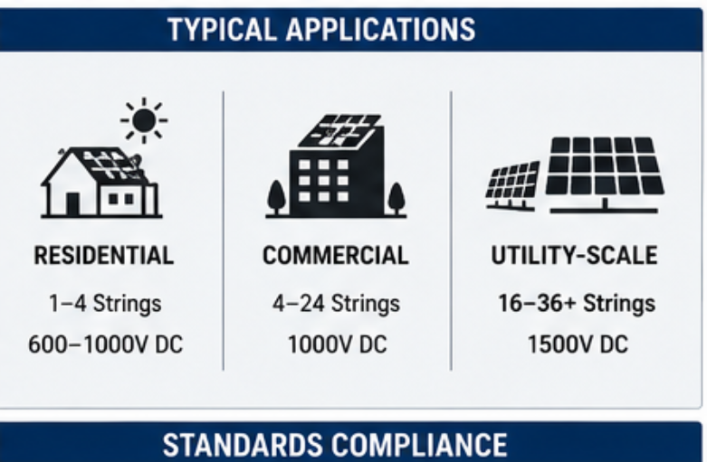
The following comparison summarizes the typical engineering differences between residential, commercial, and utility-scale photovoltaic projects.
| 기능 | 주거용 태양광 발전 | 상업용 태양광 | Utility-Scale PV |
|---|---|---|---|
| Typical DC Voltage | 600–1000V DC | 1000V DC | 1500V DC |
| 문자열 수 | 1–4 | 4–24 | 16–36+ |
| gPV Fuse Protection | Optional (depending on design) | 추천 | 필수 |
| DC 서지 보호 | 추천 | 필수 | 필수 |
| DC 차단 스위치 | 필수 | 필수 | 필수 |
| String Monitoring | Usually not required | 추천 | Standard practice |
| 원격 모니터링 | 선택 사항 | 추천 | Essential |
| 유지보수 주기 | 연간 | Every 6–12 months | Scheduled preventive maintenance |
| Cabinet Fire Protection | 선택 사항 | 추천 | Highly recommended |
| 일반적인 애플리케이션 | 홈 | 상업용 옥상 | Solar farms and utility projects |
For utility-scale projects, reliability is often more important than initial equipment cost. The financial impact of downtime can quickly exceed the investment required for higher-quality protection components.
Combiner boxes should always be designed according to the applicable electrical standards and local regulations.
The following international standards are frequently referenced in photovoltaic engineering.
| 표준 | 범위 |
|---|---|
| IEC 61439-8:2026 | PV low-voltage switchgear and controlgear assemblies |
| IEC 60269-6 | gPV fuse-links for PV string and array protection |
| IEC 61643-31 | Requirements and testing for PV DC SPDs |
| IEC 61643-32 | Selection, installation and coordination of PV SPDs |
| IEC 62548-1:2023+AMD1:2025 | PV array wiring, protection, switching and earthing |
| IEC 63112 | PV earth-fault detection and protection equipment |
| IEC TS 62738 | Ground-mounted photovoltaic power plant design |
For large ground-mounted projects, engineers should also consider IEC TS 62738, which provides guidance for the design and installation of grid-connected ground-mounted photovoltaic power plants.
Compliance with these standards improves electrical safety, simplifies project approval, and supports long-term operational reliability.
Engineers should always verify local code requirements because regulations vary between countries and project types.
If you only remember five recommendations from this guide, remember these:
It does much more than combine cables. It protects the entire DC collection system through coordinated electrical protection.
The most reliable photovoltaic systems combine:
Each layer reduces a different type of electrical risk.
Loose terminals, poor contact resistance, overloaded conductors, and aging components often generate heat long before catastrophic failure occurs.
Routine thermal imaging should be considered an essential maintenance practice.
A structured maintenance program helps detect faults before they damage inverters, cables, or other expensive equipment.
Routine inspection significantly reduces lifetime operating costs.
Most combiner box failures begin long before commissioning.
Proper component selection, correct protection coordination, good cable routing, adequate enclosure sealing, and compliance with international standards all contribute to safer and more reliable photovoltaic systems.
Projects that prioritize engineering quality during design generally experience fewer failures, lower maintenance costs, and improved long-term energy production.
A photovoltaic combiner box should never be viewed as a simple electrical enclosure.
It is the central protection hub of the DC side, integrating overcurrent protection, surge protection, isolation, monitoring, and maintenance accessibility into one coordinated system.
When combined with correctly selected gPV fuses, DC surge protective devices, disconnect switches, preventive maintenance, and cabinet fire protection, a high-quality combiner box helps maximize safety, improve system availability, reduce operating costs, and extend the service life of the entire photovoltaic installation.
For modern commercial and utility-scale solar projects, investing in a properly engineered combiner box is not an additional expense—it is an investment in long-term reliability.

