웽양 공업구 웨칭 원저우 325000
근무 시간
월요일~금요일: 오전 7시~오후 7시
주말: 주말: 오전 10시 - 오후 5시
웽양 공업구 웨칭 원저우 325000
근무 시간
월요일~금요일: 오전 7시~오후 7시
주말: 주말: 오전 10시 - 오후 5시

How to use infrared imaging to spot abnormal heating in a PV combiner box, compare like components, avoid misleading readings and plan safe follow-up.
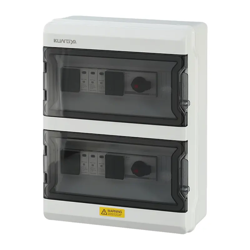
Thermal imaging can help a qualified technician find abnormal heating in a photovoltaic (PV) combiner box while current is flowing. It is a screening method, not a diagnosis by itself. A warm fuse holder, cable termination or switch may reflect normal load, a loose connection, an overloaded circuit, a damaged component or a misleading camera reading. The useful question is whether comparable parts under comparable conditions behave differently.
A PV 컴바이너 박스 brings multiple strings into a protected DC output. Each string connection, fuse holder and output termination can develop resistance or damage. NREL’s PV operation and maintenance guidance includes infrared scanning of combiner boxes to identify loose or broken connections, alongside checks for blown fuses, water intrusion and corrosion. Thermal imaging helps prioritize an investigation without claiming to identify the fault from a color alone.
Fluke’s thermography guidance stresses comparison of similar equipment under similar loads and notes that electrical loading strongly affects heat. Keep a visible-light photograph and identify the string and component in each thermal image so the finding can be repeated and reviewed.
Compare corresponding PV string fuse positions under comparable current. Heating at a terminal can prompt inspection for contact damage, an unsuitable fuse and holder combination, or a connection issue. The image alone cannot distinguish these causes. If a fuse has operated, investigate the circuit fault before replacement.
A warm entry point is not automatically a loose gland: the conductor may carry different current, receive sunlight or transfer heat from another part. Inspect the cable gland and seal for damage under the approved isolation procedure. Water ingress and corrosion can also alter contact resistance.
Compare the connection with equivalent equipment and check measured output current. The output combines strings, so it normally carries more current than an individual input. Do not interpret a hotter output as a defect merely because it differs from a string terminal. Consult the switch or busbar manufacturer’s temperature and installation instructions.
Thermography complements, rather than replaces, commissioning checks such as insulation resistance testing and string current checks. A normal-looking thermal image does not prove that polarity, insulation or overcurrent protection is correct.
No. Color palettes are relative, and apparent temperature depends on load, emissivity, reflections and camera settings. Investigate differences with electrical measurements and component data.
No. It reads the surface in its field of view. A closed-door scan may reveal external heating but cannot directly show the terminals inside. Use the enclosure’s approved inspection provisions and site safety procedure.
Keep the component location, thermal and visible images, camera settings, current, operating state, weather and corrective action. Repeat under comparable load where practicable.

