WengYang Industrial Zone Yueqing Wenzhou 325000
勤務時間
月曜日~金曜日:午前7時~午後7時
週末午前10時~午後5時
WengYang Industrial Zone Yueqing Wenzhou 325000
勤務時間
月曜日~金曜日:午前7時~午後7時
週末午前10時~午後5時
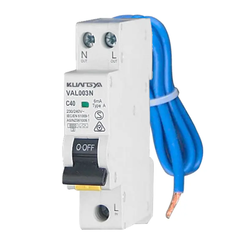
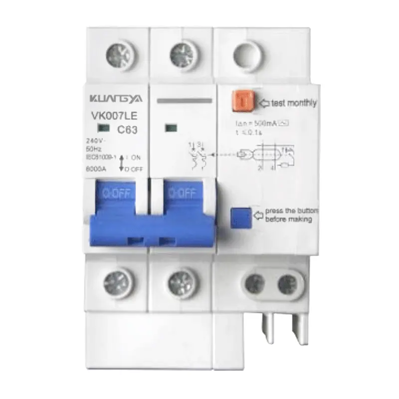
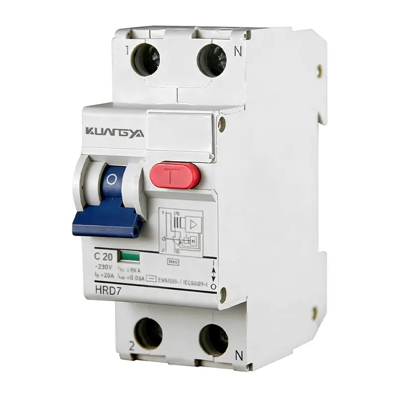
アン RCBO(過電流付き残留電流ブレーカー) は、残留電流保護と過電流保護を1つのコンパクトなモジュール式デバイスに統合しています。.
一台で RCBOブレーカー のような)リーク・プロテクションを提供する。 RCCB) および過負荷/短絡保護(たとえば エムシービー).この二重機能により、端子回路に別のRCCBとMCBを組み合わせる必要がなくなり、DINレールのスペースを節約し、配線を簡素化できます。なぜなら RCBOサーキットブレーカー は、残留電流がその感度を超えたときにトリップする(例., RCBO 30mA)または過電流が検出された場合、住宅用、商業用、そして最近では軽工業用パネルに広く採用されている。.
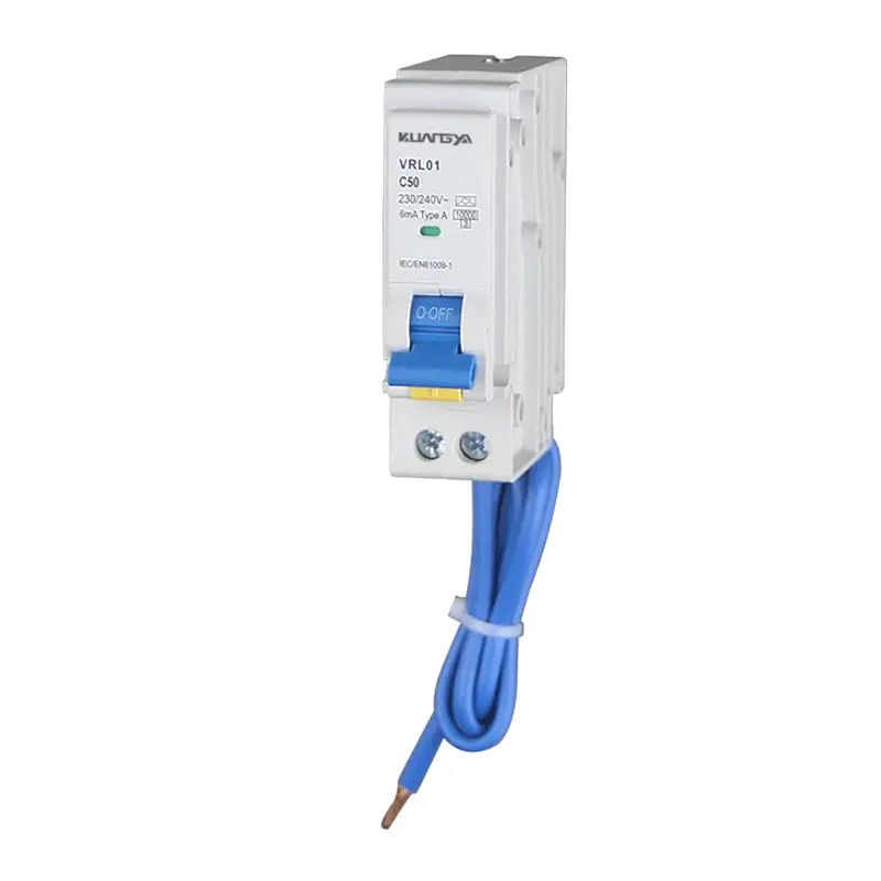
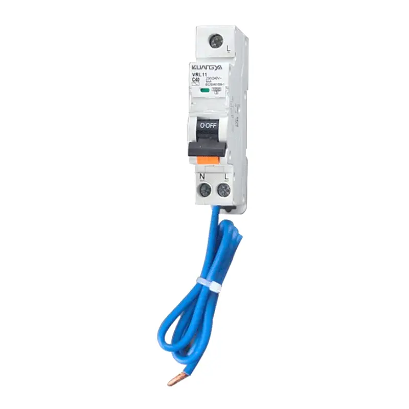
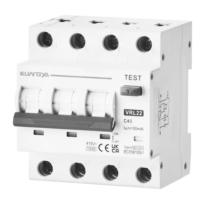
と比較して RCB対McBMCBだけでは漏電を検知できない。と比較して rcbo vs rccbRCCBだけでは過負荷や短絡を保護することはできません。RCBOは2つの保護論理を統合し、調整作業を軽減し、最終回路の選択性を高めます。設計者は通常 RCBOシングルポール (単相負荷の場合は(1P+N)、, 2極RCBO 特定の隔離のニーズに対応する 3相RCBO (3Pまたは3P+N / 4P)三相配電および機械用。.
KuangyaのRCBOポートフォリオは、突入特性に合わせた複数のトリップカーブ(B/C/D)、一般的な回路サイズに適した定格電流、および人々の保護(30 mA)と上流の識別(100/300 mA)に合わせた感度オプションをカバーしています。以下の選択ガイダンスは、以下のような典型的なアプリケーションに適した極構成、曲線、および感度の選択に役立ちます。 EV充電用RCBO そして PVシステム用RCBO インターフェース.
コンパクトな安全性:残留電流+過電流保護、最新のAC配電用に設計されています。.
RCBOは漏電検出と熱磁気過電流保護を組み合わせ、最終回路の保護設計を簡素化します。.
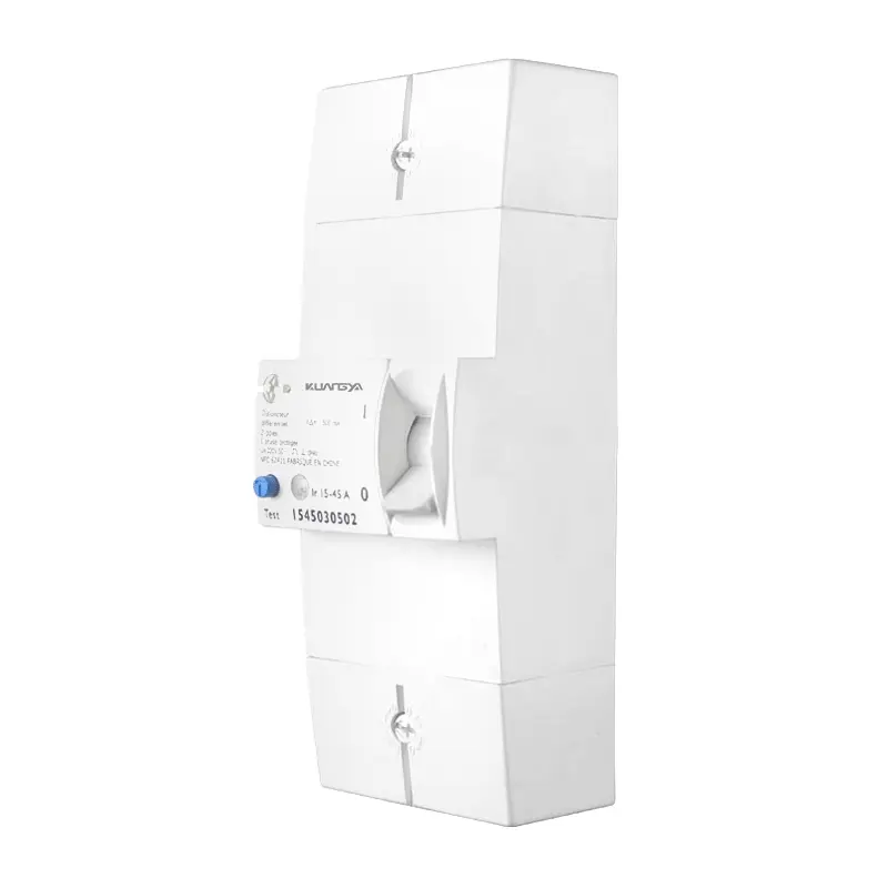
選ぶ RCBOシングルポール (1P+N)、, 2極RCBO, あるいは 3相RCBO (3P / 3P+N / 4P)で、システムのトポロジーと絶縁要件に適合します。.
一般的 RCBO 30mA 上流の選択性と火災リスク軽減のための100/300 mAのバリエーション。
負荷突入に合わせる:住宅用照明/プラグ負荷には曲線B、一般モーター負荷には曲線C、高突入機器には曲線D。.
タイプAC/A/F/B(シリーズに依存)は、パワーエレクトロニクス、ドライブ、EV/PVインターフェースを備えたアプライアンスをサポートする。.
35 mm EN 60715レールマウント、コンパクトな幅、ピン/フォーク・バスバーと互換性のある端子により、迅速な組み立てが可能。.
ステータスウィンドウとTESTボタンにより、現場での迅速なチェックが可能。.
IEC/EN 61009-1に準拠した設計(CE/CB/UKCA/RoHSなどシリーズに依存する認証はファミリーごとに取得可能)。.
家庭から商業ビル、軽工業まで、RCBOは最小限のパネルスペースで基本的な安全性を高める。.
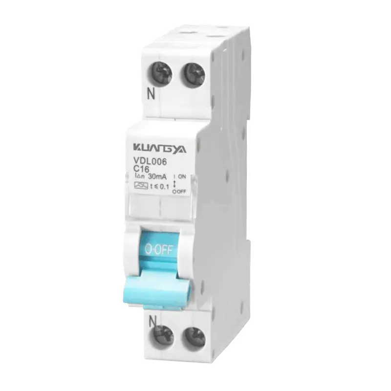
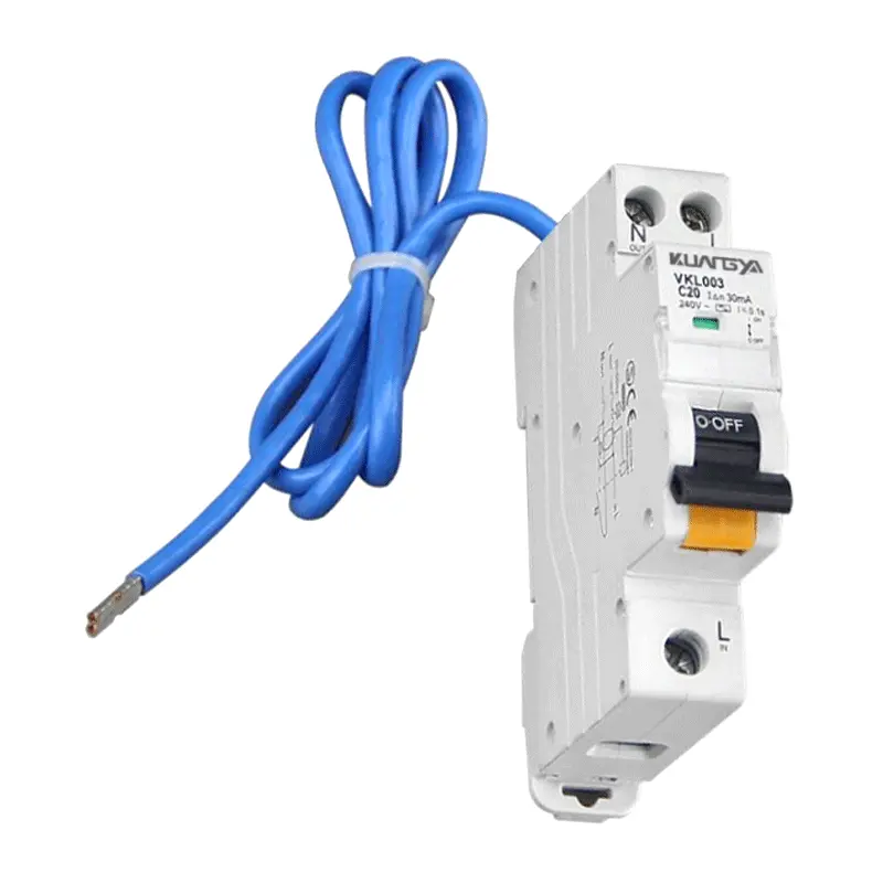
でソケットと照明回路を保護する。 RCBO 30mA 人々を守るために。. RCBOシングルポール (1P+N)は単相回路では一般的で、トラブルシューティングや絶縁を容易にします。.
オフィスや小売店では、混合負荷(LEDドライバ、IT機器)にA/F型デバイスを使用することで、脈動するDC/高周波コンポーネントを不快なトリップなしに扱うことができます。.
用途 3相RCBO 残留電流保護を維持しながら、小型モーター、コンベア、HVACギアに適切なカーブ(C/D)と感度を備えています。.
EVSEはDC残留成分を生成する可能性がある。充電器の仕様に従って、タイプA + DCモニタリングまたはタイプBを確認する。 エーエフディー そして AC SPD サイトのリスクアセスメントで必要な場合。.
PVインバータは複雑な漏れシグネチャを導入する可能性があります。インバータメーカーが指定するタイプA/F/Bを使用し、上流機器との選択的な調整を行うこと。.
継続的なサービスが重要な場合、回路ごとのRCBOは、影響を受ける分岐トリップのみの付随的な停電を最小化し、共有RCCB+MCBスキームと比較して選択性を向上させる。.
各回路の極構成、波形タイプ、トリップカーブ、定格電流、感度を選択します。.
| パラメータ | オプション | 典型的な使用例 |
|---|---|---|
| ポール | 1p+n / 2p / 3p / 3p+n / 4p | 単相回路と三相回路、絶縁の必要性、ニュートラルスイッチの要件。. |
| 波形タイプ | AC / A / F / B | それぞれ純粋なAC、AC+脈動DC、HFリッチコンバータ、スムーズDC(EV/PV)。. |
| トリップカーブ | B / C / D | B:照明/抵抗、C:混合&モーター、D:高突入機械。. |
| 感度(IΔn) | 30 / 100 / 300 mA | 人員保護用30 mA、上流選択性/火災軽減用100/300 mA。. |
| 定格電流 | ケーブルと負荷による | 設計電流に合わせ、周囲環境、グループ化、ブレーカのディレーティングを確認する。. |
正しい極性、導体のサイズ、トルク、定期的なテストを行ってください。.
ラインとニュートラルはRCBO検出コアを通過しなければならない。. RCBOシングルポール (1P+N)は、各最終回路の絶縁と故障診断を簡素化します。.
2極RCBO 特定のシステムでは完全な切断が可能;; 3相RCBO (3P/3P+N/4P)は、適切なカーブと感度で三相負荷を保護します。.
製造元のトルク仕様に従うこと;適合するピン/フォークバスバーを使用すること;ニュートラルを正しく配線すること;地域の規則に従ってTESTボタンで毎月テストを行うこと。.
| シナリオ | 推奨RCBO | 備考 |
|---|---|---|
| 住宅用ソケット/照明 | 1P+N、タイプA、30 mA、曲線B/C | 低突入;人体保護と迷惑トリップ耐性を優先。. |
| オフィスIT回路 | 1P+N、タイプA/F、30 mA、曲線C | スイッチ・モード電源→脈動DC/HF耐性のためにタイプA/Fを選択する。. |
| 小型モーター/HVAC | 3Pまたは3P+N、タイプA/F、30-100 mA、曲線C/D | モータの突入を考慮し、ドライブからの漏れパターンを確認する。. |
| EV充電器支店 | EVSE仕様によるタイプA + DCモニターまたはタイプB | メーカーに確認する。 AC SPD そして エーエフディー リスクについて. |
| PVインバーターインターフェース | インバータ仕様タイプA/F/B | マニュアルに従い、上流の保護との差別を確実にする。. |
光雅RCBOシリーズの代表的なエンベロープ値。最終的な数値は、選択したファミリーのデータシートで確認してください。.
| パラメータ | 代表値 / レンジ |
|---|---|
| 規格とコンプライアンス | IEC/EN 61009-1(内蔵過電流保護付き残留電流動作サーキットブレーカ) |
| ポール・オプション | 1P+N (RCBOシングルポール), 2P (2極RCBO)、3p、3p+n / 4p (3相RCBO) |
| 波形の種類 | AC/A/F/Bタイプ(シリーズ依存、EV/PVなど用途ごとに確認すること) |
| トリップカーブ | B / C / D(突入適応のための熱磁気特性) |
| 定格電流 (In) | 導体サイズと負荷に合わせた一般的な定格(例:6~63A、それ以上の定格はシリーズに依存) |
| 残留感度(IΔn) | RCBO 30mA 人体保護用、100/300 mA、上流選択性および火災緩和用(許可されている場合) |
| 定格動作電圧 (Ue) | 1P+N/2P:230~240V、3P/3P+N/4P:400~415V |
| 絶縁 / インパルス | Ui ≥ 500 V; Uimp 4-6 kV (直列に依存) |
| 破断容量(Icn/Ics) | 6~10 kA (Icn)範囲の熱磁気過電流遮断、サービス容量 Ics/シリーズ |
| 条件付き短絡 | Inc/IΔcについてはシリーズ表を参照。 |
| 持久力 | 機械的/電気的 ≥ 10,000動作(代表値) |
| 端子とトルク | 余裕のある端子(最大25-35 mm² Cu)、ピン/フォーク・バスバー互換、データシートによるトルク |
| 取り付け | DINレール35 mm (EN 60715); パネルレイアウトが容易なモジュラー幅 |
| 動作条件 | 周囲温度 -25 °C ... +55 °C (typ.); 高度2,000 m以下 (上記でディレーティング); シリーズごとの汚染度 |
| 保護等級 | IP20(配線時端子シールド)、フロントTEST機能 |
| コーディネーション | ブランチごとのRCBOは、共有に対して識別性を向上させる RCCB + エムシービー 組み合わせ |
| アクセサリー | 補助接点、シャント/低電圧リリース、ロック装置(シリーズにより異なる) |
| シナリオ | 推奨RCBO | なぜ |
|---|---|---|
| 家庭内の最終回路(ソケット/照明) | 1P+N、タイプA、カーブB/C、, RCBO 30mA | 一般的な突入に対する優れた耐性による人々の保護、簡単な絶縁とトラブルシューティング。. |
| オフィスIT&店舗照明 | 1P+N、タイプA/F、曲線C、30 mA | ドライバ/PSUからの脈動DC/HFコンポーネントを処理し、迷惑なトリップを低減します。. |
| 小型モーター / HVAC | 3Pまたは3P+N、タイプA/F、カーブC/D、30~100 mA | モータの突入に対応し、機器と人員の漏電保護を保持。. |
| EV充電支店 | EVSEマニュアルによる:タイプA + DCモニターまたはタイプB | 充電器によってはDC検出を内蔵しているものもあれば、外付けのタイプBが必要なものもある。. |
| PVインバーターインターフェース | インバータマニュアルによる:タイプA/F/B | リーケージシグネチャーはトポロジーによって異なる。上流プロテクションとの互換性と選択性を確保すること。. |
クアンニャRCBOファミリーは以下のように設計されている。 IEC/EN 61009-1 シリーズおよび定格に応じて、地域固有の認可を取得しています。お客様のターゲット市場向けの正確な認証セットをご請求ください。.


RCBOは、漏電保護と過電流保護を1つのデバイスに統合します。これは実質的に、分岐ごとに1つのモジュールを意味します、 配線がすっきりし、ラベル付けが明確になり、最終回路レベルでの選択性が向上します。共有 RCCB 上流、 回路ごとのRCBOでは、影響を受ける分岐のみがトリップするため、付随的な停電が減少し、故障検出が簡素化される。 故障診断が簡単になります。DINスペースが限られているレトロフィットボードでは、RCBOが、保護を追加しながら規格を満たす唯一の方法であることがよくあります。.
ほとんどの単相最終回路では、1P+Nが好ましい選択です。これは、ラインとニュートラルの両方を介して残留電流を測定し、最小限のスペースで回路を切断します。 回路を最小限のスペースで切断します。A 2極RCBO は、両方の導体の同時切断が地域の慣行で要求される場合、またはシス テムのトポロジーで要求される場合に使用できる。 またはシステムトポロジが要求する場合に使用できる。三相負荷の場合は 3相RCBO (3Pまたは3P+N/4P)を負荷電流に適合させる、 (3Pまたは3P+N/4P)は、負荷電流、突入プロファイル(カーブB/C/D)、および装置によって指定された残留電流タイプ(AC/A/F/B)に適合するサイズである。.
RCBO 30mA は、感電の危険性がある漏れ電流を確実に検出するため、最終回路の人員保護用として一般的に選択されています。 上流側のデバイス(サブメインなど)は、火災保護と選択性のために100mAまたは300mAを適用することができますが、地域の法令で許可されている場合に限ります。 医療または特殊な環境が関係する場合は、より厳しい要件が適用される場合があります。.
同じ分岐にMCBを追加する必要はありません。RCBOにはすでにMCBの熱磁気過電流エレメントが含まれています。 上流のフィーダとサブメインには、導線に合わせた適切なサイズの過電流保護が必要です。比較する場合 RCB対McB, RCBOには残留電流保護と過電流保護の両方があり、MCBには過電流保護しかないことを忘れないでください。.
別途 RCCB 1つのデバイスで複数のダウンストリームMCB保護回路を保護したい場合(コストやレガシー上の理由など)。 トレードオフは選択性の低下です。1つの回路で漏電が発生すると、共有RCCBがトリップします。回路ごとのRCBOは、トリップを影響を受ける分岐に局所化することでこれを回避します。 これは、クリティカルエリアや高可用性エリアでは望ましい。.
機器のマニュアルに従ってください。EVSEの中には、内部DCモニタリング機能を備え、外付けのタイプA RCBOを指定するものもあれば、スムーズなDCを検出するためにタイプBのデバイスを必要とするものもあります。 PVインバータはトポロジーによって異なるため、メーカーがタイプA/F/Bを指定します。DCコンポーネントが存在する場合、誤ったタイプを使用すると、死角が生じたり、迷惑なトリップが発生したりする可能性があります。 トリップの原因となります。不明な点がある場合は、選定および提出の前にサプライヤーおよびAHJに確認すること。.
曲線Bは、主に抵抗性または低突入回路(照明、レセプタクル)に適しています。曲線Cは、迷惑トリップ耐性と、混合負荷および小型モーターに対する保護のバランスが取れています。 曲線Dは、変圧器や特定の機械などの高突入機器向けです。予想される突入と上流保護との協調にカーブを合わせる。 下流の故障が最初にローカル RCBO をトリップするようにします。.
配線図は、モデルファミリーとポールオプションごとに用意されています。原則として、ラインとニュートラルの両方を RCBO センシングコアに通してください; トルク値を尊重し、不要なトリップの原因となるクロスリターン経路を避けるためにニュートラル分離を維持します。 保守を明確にするために、説明図を文書一式またはボードドアスケジュールに配置することができます。.
毎月(または地域の規則に従って)TEST ボタンを押して、残留電流トリップを確認します。終端に変色や緩みがないか目視点検する。 トリップに失敗したり、機械的な損傷が見られるデバイスはすべて交換してください。ほこりの多い環境や腐食性の環境では、点検頻度を増やし、エンクロージャを検討すること、 点検頻度を増やし、より高い IP 定格のエンクロージャを検討してください。.
はい。RCBOは漏電と過電流に対応します。 エーエフディー は火災のリスクを軽減するためにアークフォルト検出を追加する。 AC SPD 過渡過電圧に対応。選択性と性能を維持するため 選択性と性能を維持するために、メーカーのガイドラインと地域の法令に従って、設置順序と保護レベルを調整する。.
RCBOの定格は通常-25 °C ~ +55 °Cで、標準周囲温度または高度(2,000 m以上など)を超えるとディレーティングが適用されます。 データシートのディレーティングカーブを参照し、密に梱包された基板にはマージンを適用してください。 を適用してください。.