温州市岳陽工業区 325000
勤務時間
月曜日~金曜日:午前7時~午後7時
週末午前10時~午後5時
温州市岳陽工業区 325000
勤務時間
月曜日~金曜日:午前7時~午後7時
週末午前10時~午後5時
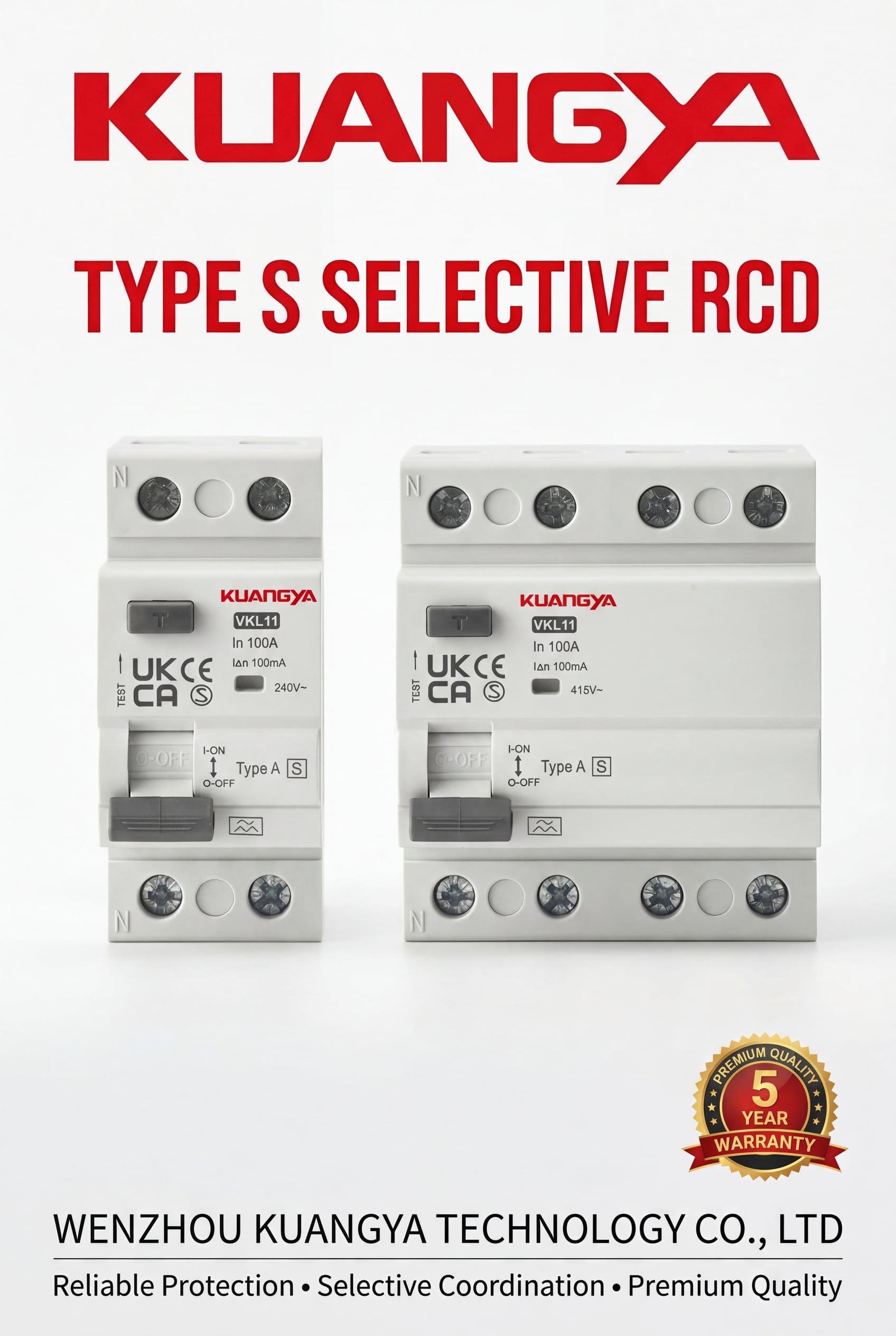
最新の設備における電気安全には、単なる保護だけでなく、インテリジェントな調整が必要です。キッチンの回路で地絡が発生した場合、建物全体が停電するのでしょうか?その答えは タイプS漏電遮断器残留電流デバイス)と選択的調整におけるその役割。この包括的なガイドでは タイプS漏電遮断器 最大限の安全性を維持しながら、完全な停電を防ぐために。.
タイプSの詳細を説明する前に、設置業者やエンジニアを混乱させがちな用語を明確にしておく必要がある。タイプ 漏電遮断器 漏洩電流を検出し、感電を防ぐために回路を遮断する装置の総称。を指す。 RCCB(残留電流サーキットブレーカー) は特定のタイプの漏電遮断器で、過電流保護を提供せずに主に残留電流を検出します。多くの地域では、これらの用語は互換性を持って使用されていますが、IEC規格ではRCCBがより一般的に使用されており、RCDはRCBO(残留電流と過電流保護を組み合わせたもの)を含むより広範なカテゴリーを包括しています。.
漏電遮断器は、差動変流器を用いて線路導体と中性導体間の電流バランスを測定することで動作します。線路導体を流れる電流と中性点を流れる還流電流が等しくない場合、その差は大地への漏電を示し、人の体や絶縁体の損傷によって漏電する可能性があります。デバイスはこの不均衡を検知して数ミリ秒以内にトリップし、致命的な負傷が発生する前に電源を切断します。この保護メカニズムは、故障電流がアース線を通って戻ってくるかどうかに関係なく機能するため、アース配線が損傷している場合でも漏電遮断器が効果を発揮します。.
タイプ S の漏電遮断器は、以下の用途に特化して設計されています。 選択的調整 (識別性または選択性とも呼ばれる)。故障電流を検知すると即座にトリップする標準的な瞬時漏電遮断器とは異なり、タイプ S の漏電遮断器には意図的な遅延時間(故障の大きさによって異なりますが、通常 130~500 ミリ秒)が設けられています。この一見直感に反するような遅延時間には重要な目的があります。それは、下流の漏電遮断器が先に漏電を除去することで、設備全体ではなく、影響を受けた回路だけが停電するようにするためです。.
技術仕様を見ると、タイプ S の動作が高度であることがわかる。IEC 規格によると、タイプ S の漏電遮断器は最小非作動時間(定格非作動電流よりも高い残留電流がデバイスをトリップさせることなく印加される最大遅延時間)を持たなければならない。瞬時漏電遮断器の場合、最大トリップ時間は定格電流(IΔn)で 0.3 秒、2×IΔn で 0.15 秒、5×IΔn で 0.04 秒です。タイプ S のデバイスは、これらの制限を IΔn で 0.5 秒、2×IΔn で 0.2 秒に拡張し、選択性に必要な時間的窓を設けています。.
タイプ S の漏電遮断器は、サージ耐量も強化されています。標準的な漏電遮断器は、IEC 61008およびIEC 61009に準拠した200Aのリング波インパルスに耐える必要がありますが、選択タイプは3000Aのインパルスサージ電流に耐える必要があります。この堅牢な構造により、雷誘発サージやモーター始動電流のような過渡事象による迷惑なトリップを防止し、システムの信頼性をさらに向上させます。.
適切な選択性がない設備では、1つの漏電が連鎖的に完全な停電につながる可能性があります。典型的な商業ビルで、1つのメイン300 mAの漏電遮断器から複数の分岐回路に給電され、それぞれが30 mAの漏電遮断器で保護されている場合を考えてみましょう。1つの分岐で故障が発生した場合(オフィスの電化製品のコードが損傷した場合など)、分岐漏電遮断器と主漏電遮断器の両方が同時に故障を検出することがあります。時間的な調整が行われないと、どちらかのデバイスが最初にトリップする可能性があり、主漏電遮断器がトリップすると、ビル全体が停電する。冷凍システムが停止し、セキュリティシステムが故障し、非常照明が不必要に作動し、生産性が低下する。.
このような選択性の欠如は、単なる不便さを超えた二次的な安全上の危険を生み出す。階段の吹き抜け、廊下、工業地帯での照明の喪失は、転倒や怪我の原因となる。クリティカルな機器は、有害な電源サイクルに見舞われる可能性がある。医療施設では、バックアップ電源による生命維持システムが不必要なリスクを生む。フードサービス業務では、腐敗による損失に直面する。データセンターではサーバーが停止する。漏電遮断器の調整不良による経済的、安全的コストは、適切なタイプS機器へのささやかな投資をはるかに上回る。.
IEC 規格は、直列に接続された漏電遮断器間の選択性を達成するための明確な規則を定めている。基本原則は以下の通りです。 上流側デバイスの感度は、下流側デバイスの感度の少なくとも3倍でなければならない。. .この 3:1 の比率により、通常のフォルト状態では、感度の高い下流側デバイスが常に最初にフォルトを検出し、上流側デバイスが応答する前にフォルトをクリアする時間が確保されます。さらに、下流側のデバイスが瞬時の場合は上流側のデバイスが選択型(S)でなければならず、下流側のデバイスがすでに選択型である場合は遅延型(R)でなければなりません。.
この規則を実際に適用すると、保護階層が形成される。最終回路の人員保護では、30 mA の漏電遮断器が心室細動を防止するために必要な感度を提供します。これより上流では、100 mA のタイプ S の漏電遮断器が 3:1 の比率(100 ÷ 30 = 3.33)を満たし、選択性に必要な時間遅延を提供します。本管では、300 mAのタイプS漏電遮断器が火災保護と最終バックアップの役割を果たし、100 mAの中間レベル(300÷100=3)と3:1の比率を維持します。この3層のアプローチにより、故障が可能な限り低いレベルで解消され、電源の可用性が最大化されます。.
メーカーによっては、IEC の最低要件を上回る測定精度を備えた漏電遮断器を提供しており、3:1 よりも低い選択比を実現しています(モデルによっては 1.25:1、2:1)。しかし、このような低い選択比は、メーカーの調整表を用いた慎重な検証が必要であり、文書なしに仮定してはならない。疑問がある場合は、保守的な3:1の比率が、あらゆる条件と装置の組み合わせにおいて信頼できる選択性を保証する。.
適切な S 形漏電遮断器を選択するには、いくつかの重要なパラメータをお客様の設置要件に適合させる必要があります。CNKUANGYAでは、住宅配電から産業用電源システムまで、様々な用途に対応したS型漏電遮断器を幅広く取り揃えております。.
感度定格は、デバイスがトリップする残留電流しきい値を決定します。保護目的および設置階層における位置によって選択します:
30 mA漏電遮断器 は、人員保護を提供し、IEC 60364 規制による「追加保護」の役割を果たします。これらのデバイスは、直接接触するシナリオで心室細動を防ぐのに十分な速さでトリップします。バスルーム、キッチン、屋外、その他の危険性の高いエリアでは、32 Aまでのソケット・コンセントの使用が義務付けられています。ただし、30 mAのデバイスは 決して タイプSは、時間遅延があるためライフセーフティ機能が損なわれます。最終回路には必ず瞬時30mA漏電遮断器を使用すること。.
100 mA タイプS漏電遮断器 選択的調整スキームにおける上流の保護として機能します。下流の30 mAデバイスと3:1の比率を維持しながら、故障保護と限定的な火災保護のための自動切断を提供します。この感度レベルは、サブ配電盤、EV充電器供給回路、および商業ビルの中間保護層に最適です。100mAのスレッショルドは、複数の下流回路にわたる累積漏れ電流による迷惑なトリップを回避するのに十分な高さですが、危険な故障を検出するには十分な感度です。.
300 mA タイプS漏電遮断器 火災保護を提供し、設備全体の主な着信保護として機能します。この感度レベルでは、直接接触による感電を防ぐことはできませんが、電気火災の原因となる絶縁不良を検出することができます。300mAの定格は、アースループインピーダンスが高いTT接地システムや、複数のサブボードに給電する主配電盤に特に適しています。このレベルは、100 mA の中間保護で 3:1 の比率を維持します。.
漏電遮断器は感度定格以外にも、検出できる残留電流波形の種類によって分類されます。最新の負荷が複雑な漏電パターンを生成するため、この分類はますます重要になってきています:
タイプ S を使用する場合、CNKUANGYA は次のことを推奨します。 最低でもタイプA 一般的な上流側の保護には、下流側の負荷特性に基づいてタイプ F またはタイプ B を指定する。EV充電器やPVインバータを使用する回路を保護する場合、上流側のタイプS漏電遮断器は、下流側の機器のタイプ要件に適合するか、それを上回る必要があります。.
定格電流(In)は、保護回路の最大負荷電流と同じか、それ以上でなければなりません。CNKUANGYAタイプS漏電遮断器の定格電流は40Aから125Aまであり、ほとんどの配電用途に対応しています。単相の場合は、ラインとニュートラルの両方を遮断する2極(2P)デバイスを選択します。三相システムの場合は、すべての活線導体を完全に絶縁するために、4極(4P)デバイスを選択します。タイプ S の漏電遮断器は、残留電流保護のみであり、過負荷および短絡保護のために MCCB またはヒューズと組み合わせる必要があります。. 引用
タイプ S の高品質漏電遮断器は、IEC 61008-1 の短絡作 動容量および遮断容量に関する要件を満たす必要があり ます。これにより、接触溶着や危険なアーク放電を起こすことなく、安全に故障電流を遮断することができます。CNKUANGYAのデバイスは、IEC、CE、RoHS準拠を含む国際規格に準拠してテストされており、仕様と承認プロセスに関する文書が用意されています。. 引用
タイプ S の漏電遮断器の効果を高めるには、適切な配線が重要です。不適切な接続は、選択性を損なったり、安全上の危険を生じたり、あるいは動作を完全に妨げたりすることがあります。.
インストールを開始する前に、以下を確認してください:
ステップ1:電源絶縁 - 設置場所の通電を遮断し、実績のある電圧テスターを使用して電圧がないことを確認します。メインの絶縁ポイントをロックアウトし、タグを付けます。.
ステップ2:取り付け - タイプ S の漏電遮断器を分電盤の DIN レールに取り付け、接続と放熱のために十分なクリアランスを確保します。保護する回路の上流側で、メインの絶縁スイッチと過電流保護の下流側に設置してください。.
ステップ 3: ライン導体の接続 - 入ってくるライン導線を、“Line In ”または供給側の記号でマークされた端子に接続する。単相の場合、これは通常左上の端子です。三相の場合は、L1、L2、L3 を適切にマークされた端子に接続します。メーカーの仕様に従ったトルクで締めます(M4端子の場合、通常2.5~4.0Nm)。.
ステップ 4: ニュートラル導体の接続 - 入力されるニュートラルを、通常「N In」とマークされているか、ライン入力に隣接して配置されているニュートラル入力端子に接続します。. クリティカル:ニュートラルは必ず漏電遮断器の変流器を通過させてください。ニュートラルは、漏電遮断器をバイパスして負荷側に直接接続しないでください。.
ステップ5:負荷導体の接続 - 通常は “Load Out ”または負荷側の記号でマークされています。ラインとライン、ニュートラルとニュートラルの極性を正しく保つ。.
ステップ6:アース接続 - アース/接地導体を電源から負荷に直接接続する、, 漏電遮断器のバイパス. .アース線は漏電遮断器の変流器を通りません。分電盤のアース線を使用してください。.
ステップ7:検証 - 通電前に目視で確認する:
設置場所への通電後:
逆極性 - 電源端子と負荷端子を接続したり、逆に負荷端子と電源端子を接続したりすると、漏電遮断器が破損したり、正常に動作しなくなることがあります。電源/負荷の表示を必ず守ってください。.
ニュートラル・バイパス - 中性点を漏電遮断器の外側に出すと、デバイスが測定できない戻り電流の経路を作り、トリップ動作を妨げます。これは、設備が保護されないままになる危険なエラーです。.
ミックス・ニュートラル - 複数の漏電遮断器を備えた分割負荷盤では、各漏電遮断器はそれぞれ絶縁されたニュートラルを持っている必要があります。RCDで保護された回路間でニュートラルを共有すると、デバイスに不均衡な電流が流れるため、迷惑なトリップが発生します。.
アーススルー漏電遮断器 - 漏電遮断器にアース線を通さないでください。アースは通常の電流経路の一部ではないため、本装置で測定するべきではありません。.
不十分な過電流保護 - 漏電遮断器は、過負荷や短絡から保護するものではありません。タイプ S の漏電遮断器の上流側には、必ず適切な MCCB またはヒューズを設置してください。.
タイプ S の漏電遮断器の技術的な性能特性を理解することで、適切な仕様と調整が可能になる。以下の表は、システム設計に不可欠なデータです。.
| 故障電流レベル | 瞬時漏電遮断器(最大トリップ時間) | タイプS漏電遮断器(最小ノントリップ時間) | タイプS漏電遮断器(最大トリップ時間) |
|---|---|---|---|
| 0.5 × IΔn | 出張は不要 | 出張は不要 | 出張は不要 |
| 1.0 × IΔn | 0.30秒 | 0.13秒 | 0.50秒 |
| 2.0 × IΔn | 0.15秒 | 0.06秒 | 0.20秒 |
| 5.0 × IΔn | 0.04秒 | - | 0.15秒 |
| 500Aサージ | トリップしてはならない | トリップしてはならない | トリップしてはならない |
最小ノントリップ時間は、タイプ S のデバイスが応答し始める前に、下流の瞬時漏電遮断器がフォルトをクリアしていることを保証します。最大トリップ時間は、下流の機器が故障した場合でも、タイプ S の漏電遮断器が安全な範囲内でバックアップ保護を提供することを保証します。.
| 上流装置 | 下流装置 | 感度比 | 選択性は達成されたか? | 使用例 |
|---|---|---|---|---|
| 100 mA タイプS | 30 mA 瞬時 | 3.33:1 | はい | 最終回路に給電するサブボード |
| 300 mA タイプS | 100 mA タイプS | 3:1 | はい | サブボードに給電するメインボード |
| 300 mA タイプS | 30 mA 瞬時 | 10:1 | はい | 最終回路に給電するメインボード |
| 100 mA 瞬時 | 30 mA 瞬時 | 3.33:1 | いいえ | どちらもトリップするかもしれない。 |
| 100 mA タイプS | 50 mA 瞬時 | 2:1 | ✗ いいえ*。 | 選択性を保証するには比率が低すぎる |
*3:1以下の比率で選択性を高めた装置を提供しているメーカーもある。特定の調整表を参照してください。.
| 申し込み | 推奨感度 | 漏電遮断器タイプ | 定格電流範囲 | ポール構成 |
|---|---|---|---|---|
| メイン受信(TTシステム) | 300 mA | タイプA/F | 63-125 A | 2p(1φ)/4p(3φ) |
| 配電盤 | 100 mA | タイプA/F | 40-100 A | 2p(1φ)/4p(3φ) |
| EV充電器の供給 | 100 mA | タイプA/B | 40-80 A | 2p(1φ)/4p(3φ) |
| PVインバーター供給 | 100 mA | タイプB | 40-63 A | 2p(1φ)/4p(3φ) |
| 工業用フィーダー | 300 mA | タイプF/B | 80-125 A | 4P(3Φ) |
| 最終サーキット | 30 mA | タイプA(瞬時) | 16-40 A | 2P (1Φ) |
注:最終回路には絶対にタイプSを使用しないでください。作業員保護のため、必ず瞬時漏電遮断器を使用してください。.
| サーキット・タイプ | 典型的な漏れ電流 | 備考 |
|---|---|---|
| コンピューター/IT機器 | デバイスあたり0.5~3 mA | 電源サイズにより増加 |
| LED照明回路 | 器具あたり0.1~0.5mA | 質の悪いドライバーの方が高い |
| 冷凍設備 | 1~5mA/ユニット | コンプレッサーの漏れ |
| HVAC可変速ドライブ | 2~10mA/ドライブ | DCコンポーネントを含むことができる |
| 長いケーブル | 0.01mA/メートル | 容量性リーク |
| EV充電器 | 3-6 mA/ユニット | フィルター・コンデンサーを含む |
複数の回路が1つの漏電遮断器を共有している場合、累積漏電量がトリップしきい値に近づく可能性があります。合計漏電量が IΔn の 50% を超えると、迷惑トリップが発生する可能性が高くなります。このため、100 mA および 300 mA のタイプ S の漏電遮断器が上流側で使用されています。.
タイプ S の漏電遮断器を直接コンセントの保護に使用することはできません。. タイプ S のデバイスは時間遅延(130-500ms)を内蔵しているため、人体保護に必要な迅速な遮断能力が損なわれています。IEC60364およびほとんどの国の電気工事規定では、特に浴室、台所、屋外などの危険性の高い場所では、最大32Aまでのソケットコンセントの追加保護用に30mAの瞬時漏電遮断器を要求しています。.
タイプ S の漏電遮断器の遅延時間は、特にマルチレベル設置における選択性を実現するために存在し、下流のデバイスが最初にトリップするようになっています。タイプ S の漏電遮断器は、30 mA の障害で最終的にトリップしますが、応答が遅れることで人体に流れる感電電流の時間が長くなり、心室細動や致命的な傷害のリスクが高まります。電気ショックの生理学的研究によると、30 mA で 40 ミリ秒を超えるトリップ時間は危険性を著しく高める。.
正しいアプリケーション:ソケットコンセントの最終回路には、瞬時 30mA タイプ A(必要な場合はタイプ F/B)の漏電遮断器または RCBO を使用する。100mAと300mAのタイプSを上流側(分電盤や主入力側)に予備し、下流側の30mAと協調させることで、全停電を防ぐと同時に、使用箇所のライフセーフティ保護を維持する。. 引用
単一回路の故障による全停電は、漏電遮断器の選択性が不足していることを示しています。これは通常、主電源と分岐電源の両方に瞬時漏電遮断器を設置している場合、または上流側と下流側の機器の感度比が不十分な場合に発生します。.
この解決策には3段階のアプローチがある。:
ステップ1:現在の設定を確認する。. 設置されているすべての漏電遮断器を確認し、感度の定格と瞬時漏電遮断器かタイプ S かをメモしてください。一般的に問題となる構成には、メインに 100mA の瞬時漏電遮断器、分岐に 30mA の瞬時漏電遮断器があり、両方のデバイスが同時に故障を検知し、どちらかが先にトリップする可能性があります。.
ステップ2:適切な階層構造を導入する。. メインの漏電遮断器を300mAのタイプS(最低でもタイプA、VFDまたはEV充電器がある場合はタイプFまたはB)に交換してください。中間配電盤がある場合は、それらの配電盤に100 mAのタイプS漏電遮断器を取り付けてください。最終回路にある既存の30 mAの瞬時漏電遮断器はそのままにしてください。.
ステップ3:3:1の比率を確認する。. 各上流デバイスの感度が、その下流デバイスの感度の少なくとも3倍であることを確認してください:300mA ÷ 100mA = 3:1✓、100mA ÷ 30mA = 3.33:1✓ です。この比率とタイプ S のタイムディレイを組み合わせると、下流のデバイスが常に最初にトリップするようになります。.
シナリオ例:商業用オフィスビルのメイン受電盤には300mAのタイプS漏電遮断器があり、3つのサブ盤にそれぞれ100mAのタイプS漏電遮断器が設置されている。各サブボードは、30mAの瞬時RCBOで保護された複数のオフィス回路に給電している。あるオフィスで故障が発生すると(おそらくノートパソコンの充電器が破損した)、その回路用の30mAのRCBOが40ミリ秒以内にトリップする。そのサブボードにある100 mAのタイプS漏電遮断器は故障を検知しますが、トリップを開始するまでに130ミリ秒以上待ちます。300mAのメイン漏電遮断器が最終的なバックアップを行うが、動作する必要はない。結果:停電するのは影響を受けたオフィスだけで、ビルの他の部分は通常通り稼動しています。.
この選択的な調整により、電力利用可能性が劇的に改善され、メンテナンスコールが減少し、休憩室の冷蔵庫の食品の腐敗が防止され、セキュリティシステムが維持され、予期しない全停電に伴う安全上の危険が排除される。上流位置にタイプS漏電遮断器を設置することで、わずかなコストで運用と安全に大きなメリットをもたらします。.
タイプ S の漏電遮断器を使いこなすことで、電気安全は単純な「トリップするかしないか」の二者択一から、洗練された重層的な防御システムへと変貌する。適切な選択性により、保護が可能な限り低いレベルで動作し、影響を受けない回路への電力を維持しながら故障を隔離します。このアプローチにより、信頼性の高い保護による安全性の向上、ダウンタイムと損失を低減する電力供給能力の向上、故障の局所化によるトラブルシューティングの簡素化、選択的協調をますます義務付ける最新の電気規格への準拠など、複数の利点が得られます。.
上流側と下流側の感度比を 3:1 に維持すること、上流側(100 mA と 300 mA)にのみタイプ S を使用すること、作業員の安全のために 30 mA の保護を瞬時に維持すること、接続される負荷に適した漏電遮断器のタイプ(A/F/B)を選択すること、メーカのテーブルとの調整を確認すること、そして定期的にテストを行い、継続的な保護を確保することです。タイプ S の漏電遮断器を指定する場合、CNKUANGYA は IEC コンプライアンス、技術サポート、およびグローバルな供給体制に裏打ちされた包括的なソリューションを提供します。.
詳細な製品仕様、調整表、アプリケーション・サポートについては、こちらをご覧ください。 cnkuangya.com または、資格のある電気技師に相談し、お客様の施設固有の要件に合わせた選択型漏電遮断器システムを設計してください。適切な選択性は単なる優れたエンジニアリングではなく、ちょっとした不都合と施設全体の停電の違いです。.
キーワード:タイプ S の漏電遮断器、選択的な漏電遮断器、時間の遅れの漏電遮断器、RCCB の選択性、漏電遮断器の調整、残りの流れ装置、地絡の保護、電気安全、100mA 漏電遮断器、300mA 漏電遮断器、漏電遮断器の配線、停電を防いで下さい、識別の漏電遮断器、タイプ A の漏電遮断器、タイプ B の漏電遮断器、IEC 61008、電気取付け、回路の保護、迷惑な低下、CNKUANGYA を
