Zona industriale di WengYang Yueqing Wenzhou 325000
Orario di lavoro
Da lunedì a venerdì: dalle 7.00 alle 19.00
Fine settimana: 10.00 - 17.00
Zona industriale di WengYang Yueqing Wenzhou 325000
Orario di lavoro
Da lunedì a venerdì: dalle 7.00 alle 19.00
Fine settimana: 10.00 - 17.00

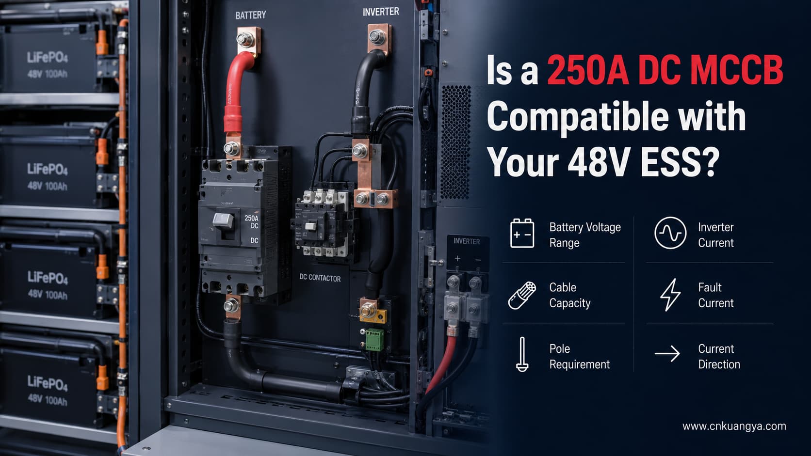
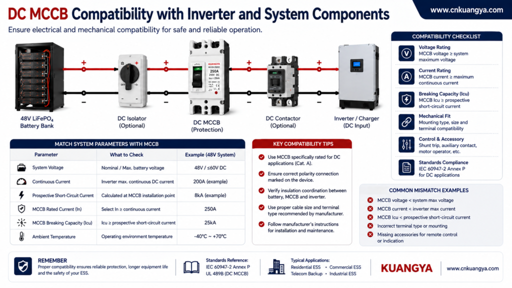
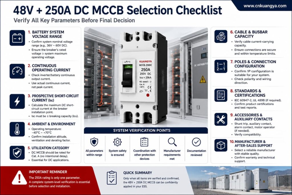
A MCCB CC da 250A per ESS a 48V può essere una scelta idonea per alcuni sistemi di accumulo di energia a batteria, ma le etichette “48V” e “250A” da sole non sono sufficienti a confermare la compatibilità.
Prima di selezionare l'interruttore, è necessario verificare la potenza continua reale dell'inverter, la tensione minima della batteria, la corrente massima di carica e scarica, la capacità dei cavi, la corrente di guasto disponibile, i requisiti dei poli, la direzione della corrente e le prestazioni in CC documentate dell'interruttore.
Se uno qualsiasi di questi parametri è sconosciuto, l'interruttore deve essere considerato non confermato piuttosto che presunto idoneo.
Utilizzare la seguente tabella solo come strumento di selezione preliminare.
| Risultato preliminare | Cosa significa |
|---|---|
| Possibile candidato | La corrente continua è inferiore a 250A e i restanti parametri elettrici possono essere verificati |
| È richiesta una revisione dettagliata | La corrente continua si avvicina alla corrente nominale dell'interruttore |
| Solitamente non adatto per il pieno carico continuo | La corrente continua calcolata raggiunge o supera i 250A |
| Non confermabile | Corrente di guasto, portata dei cavi, numero di poli, sistema di messa a terra o direzione della corrente sconosciuti |
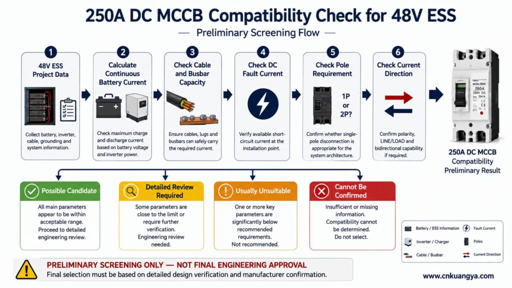
Importante: Queste categorie non sono intervalli di selezione degli interruttori definiti dalla norma IEC. Rappresentano solo un primo controllo pratico.
Una corrente calcolata inferiore a 250A non non conferma automaticamente che un MCCB da 250A sia idoneo.
La selezione finale deve verificare anche:
Per i principi generali su tensione, corrente, potere di interruzione, poli e coordinamento degli interruttori ESS, fare riferimento alla nostra Guida alla selezione degli interruttori automatici DC per ESS.
Se desideri prima comprendere perché un sistema a batteria a bassa tensione richiede comunque una protezione DC dedicata, leggi la nostra guida che spiega perché un ESS a 48V necessita di un interruttore automatico DC dedicato.
Un acquirente non dovrebbe inviare solo:
“Batteria da 48V, inverter da 10kW, necessario interruttore da 250A.”
Tali informazioni non sono sufficienti per la selezione del modello finale.
I seguenti parametri devono essere forniti prima dell'acquisto di un MCCB CC da 250A per ESS a 48V.
| Parametro richiesto | Informazioni da fornire | Perché è importante |
|---|---|---|
| Tensione nominale della batteria | 48V, 51,2V, ecc. | Classificazione di base del sistema |
| Tensione operativa minima | Minimo effettivo consentito da batteria e inverter | Una tensione più bassa aumenta la corrente |
| Tensione massima di carica | Massima tensione attendibile della batteria | Deve rimanere entro la tensione nominale DC dell'interruttore automatico |
| Potenza di uscita continua dell'inverter | Potenza di uscita reale in watt | Utilizzato per la stima della corrente |
| Corrente di carica massima | Valore del produttore | La corrente può fluire verso la batteria |
| Corrente massima di scarica | Valore batteria/BMS | Limita la corrente continua utilizzabile |
| Corrente di picco | Intensità e durata | Deve essere coordinato con le caratteristiche di intervento dell'interruttore |
| Sezione del cavo | Inclusi conduttori in parallelo | L'interruttore deve proteggere il cavo |
| Metodo di installazione del cavo | Armadio, condotto, aria libera, raggruppato, ecc. | Modifiche alla portata di corrente ammissibile del cavo |
| Portata nominale della sbarra | Capacità di corrente continua | Deve essere coordinato con l'interruttore |
| Corrente di guasto presunta | Nel punto di installazione dell'interruttore | Determina il potere di interruzione richiesto |
| Schema di messa a terra | Messa a terra, isolato (IT), monitorato tramite isolamento | Influenza la scelta del numero di poli |
| Isolamento richiesto | Un conduttore o entrambi i conduttori | Determina se un interruttore unipolare (1P) è appropriato |
| Direzione della corrente | Unidirezionale o bidirezionale | Deve corrispondere alla capacità dell'interruttore |
| Temperatura ambiente | All'interno dell'armadio ESS | Potrebbe richiedere un declassamento |
| Modello dell'inverter | Produttore e modello esatti | Consente la verifica manuale |
| Modello della batteria | Produttore e modello esatti | Fornisce i limiti della batteria |
L'obiettivo non è semplicemente trovare un interruttore in grado di sopportare la corrente prevista.
L'obiettivo è trovare un dispositivo di protezione in grado di proteggere correttamente l'intero circuito lato batteria.
Un punto di partenza utile per stimare la corrente lato batteria dell'inverter è:
I_DC = P_AC ÷ (V_batteria × η)
Dove:
Ad esempio:
95% efficienza = 0,95
Questa è solo una stima a regime stazionario.
Non include automaticamente:
Questa distinzione è importante.
An inverter sold as a “10kVA” model does not automatically provide 10kW of continuous real output.
For example, a published 48V/10,000VA inverter/charger lists 8,000W continuous real output at 25°C, while its model designation is 10,000VA. The same manufacturer lists a maximum efficiency of 95%.
Therefore, always use the manufacturer’s continuous real power in watts when performing the current calculation.
The following examples assume an inverter efficiency of 95%.
The 95% value is an assumption for comparison. Actual inverter efficiency varies with load, battery voltage, temperature, and product design.
Three different battery voltages are shown:
| Continuous AC Output | At 48V | At 44.8V | At 42V | Preliminary 250A Assessment |
|---|---|---|---|---|
| 5kW | 109.6A | 117.5A | 125.3A | A 250A breaker may be too large for some conductor-protection arrangements |
| 8kW | 175.4A | 188.0A | 200.5A | Possible candidate, but full verification is still required |
| 10kW | 219.3A | 235.0A | 250.6A | Close to the rating at 44.8V and above it at 42V |
| 12kW | 263.2A | 282.0A | 300.8A | Calculated continuous current already exceeds 250A |
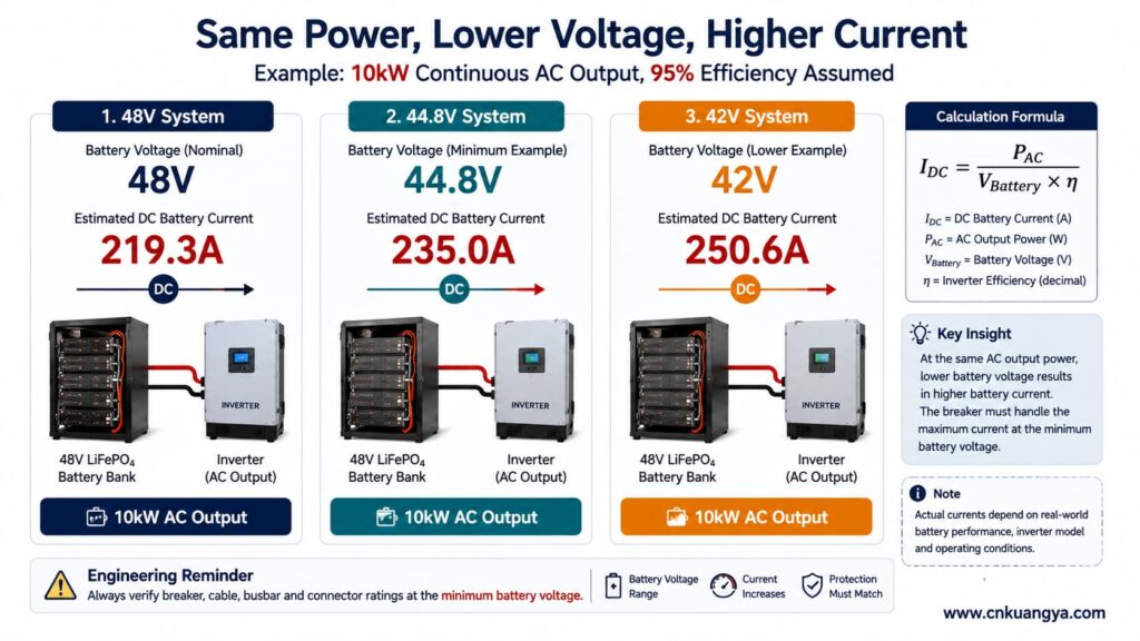
These calculations do non prove whether the breaker is suitable.
They only answer one question:
Is the expected steady-state battery current obviously inconsistent with a 250A breaker?
If the result is already above 250A, the mismatch is clear.
If the result is below 250A, additional engineering checks are still required.
A “48V battery system” does not remain at exactly 48.0V during operation.
Actual voltage changes with:
For the same output power:
Lower battery voltage means higher battery current.
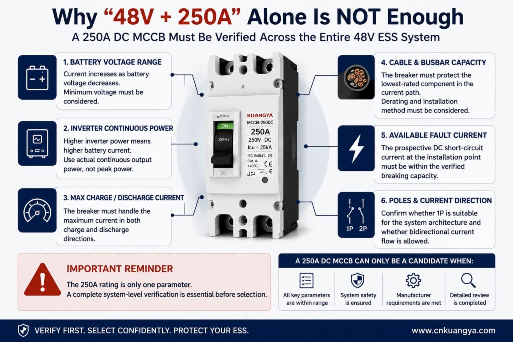
That is why using only the nominal 48V value can underestimate the maximum continuous current.
Consider one documented 51.2V/100Ah LiFePO4 battery.
The manufacturer publishes the following values:
| Battery Parameter | Published Value |
|---|---|
| Tensione nominale | 51.2V |
| Nominal capacity | 100Ah |
| Nominal energy | 5.12kWh |
| Maximum continuous discharge current | 100A |
| Maximum 10-second discharge current | 200A |
| End-of-discharge voltage | 44.8V |
| Charging voltage | 56–56.8V |
| Maximum continuous charge current | 100A |
These values are listed in the manufacturer’s current technical data.
For this specific battery example, 44.8V is the published end-of-discharge voltage.
Therefore, if this battery is being used as the reference, the calculation should not silently substitute 42V.
A 42V calculation can still be technically useful—but only for a system whose actual manufacturer documentation permits operation at or near 42V.
Ad esempio:
10kW output, 42V battery voltage, 95% assumed efficiency:
10,000 ÷ (42 × 0.95) ≈ 250.6A
10kW output, 44.8V end-of-discharge voltage, 95% assumed efficiency:
10,000 ÷ (44.8 × 0.95) ≈ 235.0A
These are two different operating assumptions.
The 250.6A result must not be presented as though it comes from the documented battery whose end-of-discharge voltage is 44.8V.
This distinction is particularly important when deciding whether a 250A DC MCCB is close to its expected continuous-current limit.
Before evaluating a specific 250A model, buyers who need a broader explanation of DC MCCB ratings, breaking capacity and application requirements can review our DC MCCB selection and standards guide.
For the KUANGYA 250A DC MCCB discussed in this application, the key product parameters used for compatibility review include:
| Parametro | Product Value to Confirm |
|---|---|
| Product type | DC molded case circuit breaker |
| Modello | MCCB-250DC |
| Numero di pali | 1P |
| Corrente nominale | 250A |
| Tensione operativa nominale | 250 V CC |
| Ultimate breaking capacity | Icu 25kA |
| Service breaking capacity | Confirm against current product documentation |
These values describe the breaker.
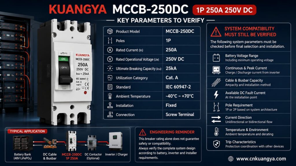
Buyers can review the current MCCB-250DC 1P 250A 250V DC product specifications before submitting system data for compatibility confirmation.
They do non, by themselves, prove compatibility with a specific ESS.
Ad esempio:
A breaker may have a 250A rated current, but the cable may not safely carry 250A.
A breaker may have a high short-circuit rating, but the published value must be confirmed for the actual:
For this reason, final selection should use the actual datasheet and technical documentation supplied with the offered product—not an AI-generated product image or recreated nameplate.
The words “250A, 250V DC” do not provide enough information for final engineering approval.
Before ordering, confirm the following where applicable.
| Articolo | Perché è importante |
|---|---|
| Time-current characteristic | Determines overload response |
| Instantaneous trip setting | Determines high-current fault response |
| Derating per temperatura ambiente | Important in hot ESS cabinets |
| Terminal temperature limits | Can restrict continuous current |
| Maximum conductor size | Must accept the actual battery cable |
| Coppia di serraggio | Critical for low-resistance high-current joints |
| Mounting orientation | May affect thermal performance |
| LINE/LOAD requirements | Some DC products require a specific direction |
| Polarity requirements | May affect arc interruption |
| Bidirectional capability | Important when charging and discharging share one circuit |
| Isolation suitability | Required if breaker is used as an isolating device |
| Breaking-capacity test data | Confirms actual DC interruption conditions |
| Certification scope | Must cover the exact product and market |
If any of these parameters are critical to the project but unavailable, the product should remain unconfirmed until the manufacturer provides the required information.
A MCCB CC da 250A per ESS a 48V may be considered when the following conditions can be verified.
A nominal 48V or 51.2V battery system may operate at a considerably higher voltage while charging.
For example, the published 51.2V LiFePO4 battery discussed above specifies a charging voltage between 56V and 56.8V.
The breaker voltage rating must therefore be checked against maximum system voltage, not only nominal voltage.
A 250V DC breaker may appear to provide substantial voltage margin in a 48V-class ESS, but this only confirms one part of the compatibility check.
It does not confirm:
Suppose the calculated battery current is 188A.
A 250A breaker may appear reasonable from the current rating alone.
But actual performance also depends on:
The same issue becomes more important when calculated current approaches 230–240A.
Ad esempio:
235A < 250A
is mathematically true.
But that does not automatically prove that the breaker can carry 235A continuously in a hot battery cabinet without approaching its thermal trip region.
The actual trip curve and manufacturer derating information are required.
One of the most important breaker-selection principles is often overlooked:
The breaker is not selected only to carry the load. It must also protect the conductors.
The complete current path can contain:
The lowest-rated component must be considered.
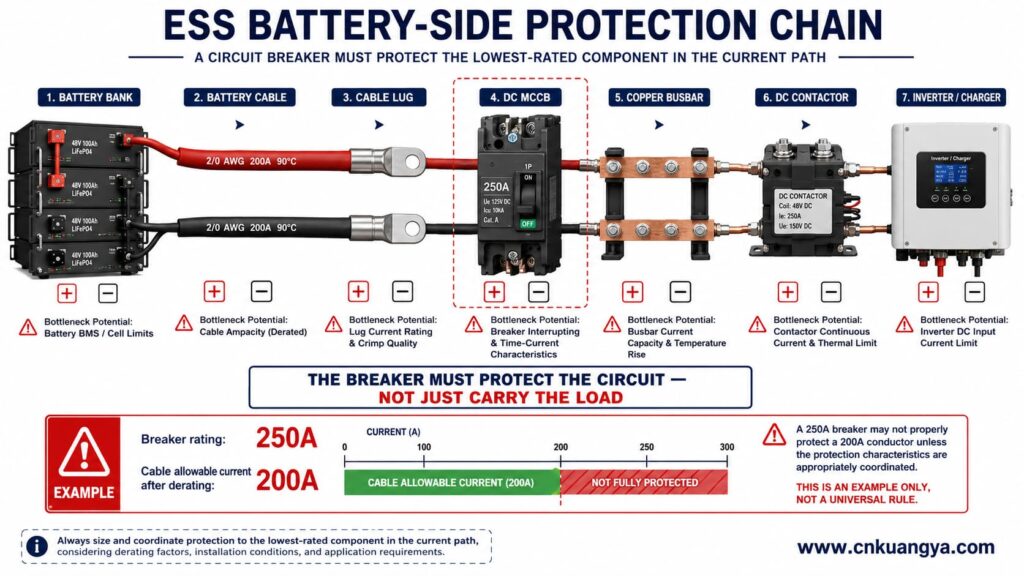
For example, if a cable can safely carry only 200A after temperature and installation derating, selecting a 250A breaker simply because the inverter may draw 180A does not automatically provide correct conductor protection.
The cable calculation must be reviewed separately.
A battery bank can supply substantial short-circuit current.
Prospective fault current depends on:
The circuit breaker must be capable of interrupting the prospective DC fault current at its installation point.
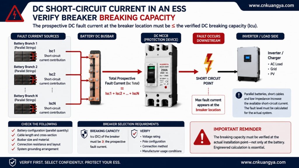
ABB’s technical application guide on circuit breakers for direct current applications provides additional engineering guidance on DC network configurations, earthing arrangements, protective-device selection and short-circuit calculations.
Do not use a simple rule such as:
“Fault current is below 25kA, so the breaker is automatically suitable.”
A more accurate statement is:
The prospective fault current must not exceed the breaker’s verified DC breaking capacity at the applicable voltage, pole configuration, connection method, and test conditions.
IEC 60947-2:2024 applies to low-voltage circuit breakers with rated circuit voltages up to 1,000V AC or 1,500V DC. It does not mean every breaker covered by the standard has the same DC breaking capacity.
The product-specific data still control the final selection.
For projects requiring UL certification, the UL molded-case circuit breaker marking and application guide also identifies dedicated markings and wiring requirements for circuit breakers evaluated for battery power-supply systems.
The KUANGYA product being evaluated is a 1P device.
That means the project must answer an important question:
Is single-conductor disconnection appropriate for this ESS?
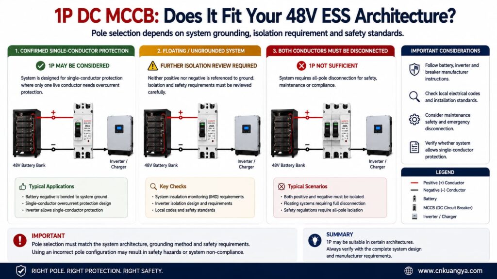
A 1P breaker may be considered where:
A 1P breaker should non automatically be selected where:
There is no universal rule that says:
“Every 48V ESS needs 1P.”
There is also no universal rule that says:
“Every 48V ESS needs 2P.”
The system architecture determines the answer.
Battery energy storage systems can operate in two directions.
During discharge:
Battery → Inverter → AC load
During charging:
Charger/Inverter → Battery
That means the same battery cable may carry current in opposite directions at different times.
Some DC protection devices are designed for bidirectional operation.
Others may have:
Therefore, the words:
250A / 250V DC
do not automatically prove that a breaker can interrupt fault current safely in both directions.
Before using the MCCB in a bidirectional ESS circuit, confirm:
If the manufacturer has not documented bidirectional interruption capability, do not claim that capability in the project specification.
A useful compatibility guide should explain not only when a product may work, but also when it should non be selected.
Do not approve this 250A 1P DC MCCB solely because the system is described as “48V”.
Further review or another protective device is required when:
Missing information should not be treated as permission to assume compatibility.
Assume:
| Parametro | Valore |
|---|---|
| Continuous real AC output | 5,000W |
| Battery voltage under load | 44.8V |
| Assumed inverter efficiency | 95% |
Calcolo:
I_DC = 5,000 ÷ (44.8 × 0.95)
I_DC ≈ 117.5A
The estimated continuous current is substantially below 250A.
However:
A 250A breaker is not automatically better simply because its rated current is much higher than 117.5A.
The real questions are:
For a relatively small 5kW system, a 250A breaker may be oversized for some designs.
Assume:
| Parametro | Valore |
|---|---|
| Continuous real AC output | 8,000W |
| Battery voltage under load | 44.8V |
| Assumed inverter efficiency | 95% |
Calcolo:
I_DC = 8,000 ÷ (44.8 × 0.95)
I_DC ≈ 188.0A
A 250A breaker may enter the candidate range.
But before approving it, verify:
The 188A calculation is a useful screening result—not a final selection.
Assume:
| Parametro | Valore |
|---|---|
| Continuous real AC output | 10,000W |
| Battery voltage under load | 44.8V |
| Assumed inverter efficiency | 95% |
Calcolo:
I_DC = 10,000 ÷ (44.8 × 0.95)
I_DC ≈ 235.0A
The calculated current is below 250A but relatively close to the breaker rating.
This is a case where simply saying:
“235A is below 250A, so use a 250A breaker.”
would be too simplistic.
The project must determine:
A detailed engineering review is required.
Now consider a different system where the battery and inverter documentation actually permit operation at 42V.
| Parametro | Valore |
|---|---|
| Continuous real AC output | 10,000W |
| Battery voltage under load | 42V |
| Assumed inverter efficiency | 95% |
Calcolo:
I_DC = 10,000 ÷ (42 × 0.95)
I_DC ≈ 250.6A
The estimated steady-state current already slightly exceeds 250A.
Under these assumptions, a 250A breaker should not simply be selected for continuous 10kW operation.
The project may need to reconsider:
Again, this 42V example is a generic system example.
It is not the published lower-voltage limit of the 51.2V battery discussed earlier.
A published 48V/10,000VA inverter/charger demonstrates why a simple current calculation cannot determine the final protection device.
The manufacturer lists approximately:
| Parametro | Published Value |
|---|---|
| Model class | 48V / 10,000VA |
| Continuous real output at 25°C | 8,000W |
| Continuous real output at 40°C | 7,000W |
| Continuous real output at 65°C | 6,000W |
| Maximum efficiency | 95% |
| Peak power | 18,000W |
| Recommended battery fuse | 400A |
| Recommended cable for 0–5m | 2 × 50mm² per polarity |
| Recommended cable for 5–10m | 2 × 70mm² per polarity |
These values are published in the current installation manual.
At 44.8V and an assumed 95% efficiency, 8,000W produces an estimated current of approximately:
188A
Yet the manufacturer recommends a 400A battery fuse for the relevant model.
That does not mean the inverter continuously consumes 400A.
It demonstrates that final protective-device selection can also depend on:
Most importantly, the manufacturer explicitly instructs installers to use the correct protective device and not substitute a different type without referring to the documentation.
Pertanto:
A manufacturer-specified 400A fuse cannot automatically be replaced by a 400A MCCB—or a 250A MCCB—simply because the ampere numbers appear reasonable.
Now consider two identical 51.2V/100Ah batteries connected in parallel.
Each published battery has:
Assuming correct and balanced parallel operation:
100A + 100A = 200A
So the theoretical combined continuous discharge capability is 200A.
Does that automatically mean one 250A main breaker is correct?
No.
The main breaker must still be coordinated with the total output conductors, but each battery branch must also be evaluated separately.
If one battery branch develops a fault, the healthy parallel branch may contribute current into that fault.
Therefore, branch protection may be required according to:
Do not publish a specific branch fuse rating such as “125A” unless the rating is supported by the actual battery, cable, and protection calculation.
A technically safer description is:
Individual Branch Protection — Size According to Battery, Cable and System Limits
Because the breaker under consideration is a 1P product, current calculation alone is not enough.
| System Arrangement | Preliminary Assessment |
|---|---|
| Confirmed single-conductor protection architecture | 1P may be considered |
| One conductor intentionally grounded | Requires system and regulatory review |
| Floating battery system | Additional isolation review normally required |
| Positive and negative must both be disconnected | 1P is not sufficient |
| Inverter manufacturer requires 2P | Do not substitute a 1P device |
| Grounding arrangement unknown | Compatibility cannot be confirmed |
| Single-pole voltage rating is sufficient | Other checks are still required |
The important principle is:
Pole selection is determined by system architecture, not simply by system voltage.
Possibly.
A battery protection system can use different architectures, including:
A fuse and an MCCB are not identical devices.
For a more detailed comparison of reset capability, interruption behavior, maintenance and typical applications, read our DC circuit breaker vs DC fuse guide.
They may differ in:
For that reason, do not assume:
250A fuse = 250A MCCB
oppure:
400A fuse = 400A MCCB
A manufacturer-specified fuse rating should only be replaced by another protective device after the protection coordination has been reviewed.
For a serious ESS project, the purchasing decision should not depend only on a product-page headline.
Ask for the documentation relevant to your installation.
| Document or Data | Perché è importante |
|---|---|
| Product datasheet | Confirms the offered model |
| Dimension drawing | Confirms cabinet fit |
| Installation instructions | Confirms wiring requirements |
| DC breaking-capacity data | Confirms tested interruption conditions |
| Time-current curve | Supports protection coordination |
| Temperature-derating data | Important for ESS cabinets |
| Terminal specification | Confirms cable size and torque |
| Polarity statement | Confirms conductor connection requirements |
| Current-direction statement | Helps verify bidirectional ESS use |
| Applicable test report | Supports technical ratings |
| Certificate scope | Confirms model and standard coverage |
| OEM drawing | Confirms permitted branding changes |
Document availability should be confirmed before ordering.
Do not assume that every document is available simply because a parameter appears in an online listing.
Before approving a MCCB CC da 250A per ESS a 48V, every item below should have a clear answer.
| Compatibility Check | Requisiti |
|---|---|
| Maximum battery voltage | Within breaker DC voltage rating |
| Tensione operativa minima | Confirmed from actual system |
| Continuous battery current | Calculated and verified |
| Corrente massima di scarica | Confirmed |
| Corrente di carica massima | Confirmed |
| Corrente di picco | Compatible with trip behaviour |
| Capacità del cavo | Properly protected |
| Busbar capacity | Suitable for continuous current |
| Corrente di guasto presunta | Within verified DC breaking capacity |
| Numero di pali | Compatible with architecture |
| Messa a terra | Confirmed |
| Isolation requirement | Confirmed |
| Direzione della corrente | Documented |
| Temperatura | Derating checked |
| Inverter requirements | Followed |
| Battery requirements | Followed |
| Fuse requirements | Not improperly substituted |
| Required certification | Confirmed |
If one of the critical items is unknown, the correct result is:
Compatibility not yet confirmed.
To reduce back-and-forth communication with the breaker supplier, send the following information with your enquiry:
Battery Information
Inverter / PCS Information
Cable and Busbar Information
Protection System Information
Commercial Information
For a project form, a stronger CTA than a generic “Submit” button is:
Check 250A MCCB Compatibility
No.
Using a 95% assumed efficiency:
At 48V:
10,000 ÷ (48 × 0.95) ≈ 219.3A
At 44.8V:
10,000 ÷ (44.8 × 0.95) ≈ 235.0A
At 42V:
10,000 ÷ (42 × 0.95) ≈ 250.6A
The result changes significantly with battery voltage.
Final selection also depends on the actual inverter continuous power, manufacturer requirements, cable size, trip characteristics, battery limits, and fault current.
It is numerically below 250A, but the margin is small.
A detailed review is required for:
Do not approve the breaker based only on the difference between 235A and 250A.
Not automatically.
The two devices can have different:
Use the equipment manufacturer’s specified protective device unless an alternative has been properly verified.
No.
A 1P device may be suitable in an approved single-conductor protection architecture.
It may not be appropriate where:
If charging and discharging use the same circuit, normal current can flow in both directions.
The breaker must therefore be checked for:
Do not infer bidirectional capability from the rated current and voltage alone.
Not automatically.
The published breaking capacity must be verified for the actual:
Prospective fault current at the installation point must also be established.
No.
Battery ampere-hour capacity describes stored charge.
It does not directly define:
Use the battery manufacturer’s current limits and complete electrical design.
No.
An oversized breaker can fail to adequately protect:
The protective device must be coordinated with the protected circuit.
A MCCB CC da 250A per ESS a 48V may be a valid candidate for some battery energy storage systems, but it should never be selected from “48V + 250A” alone.
A proper compatibility decision verifies:
The current calculation is a useful first filter.
È not the final engineering answer.
If your continuous-current estimate approaches the breaker’s 250A rating, or if fault current, trip data, grounding, cable capacity, or current direction is unknown, the correct next step is to verify the complete system rather than assume compatibility.
Review the KUANGYA DC MCCB range for available configurations and technical parameters, then check the MCCB-250DC product specifications and provide your actual ESS project data before requesting final model confirmation and quotation.

