Zona industriale di WengYang Yueqing Wenzhou 325000
Orario di lavoro
Da lunedì a venerdì: dalle 7.00 alle 19.00
Fine settimana: 10.00 - 17.00
Zona industriale di WengYang Yueqing Wenzhou 325000
Orario di lavoro
Da lunedì a venerdì: dalle 7.00 alle 19.00
Fine settimana: 10.00 - 17.00
COSA È MCCB: Sono le 3 del mattino e squilla il telefono. La linea di produzione principale del vostro stabilimento è silenziosa, i pannelli di controllo sono scuri e nell'aria si sente un leggero odore di plastica bruciata. Il colpevole? Un MCCB di distribuzione principale che non è intervenuto durante un guasto, causando un guasto catastrofico del pannello invece di un arresto controllato e isolato. Nei miei oltre 15 anni di lavoro come ingegnere sul campo ho assistito a questo esatto scenario più volte di quante ne possa contare. Un dispositivo che costa poche centinaia di dollari, ignorato e ritenuto funzionante, finisce per causare centinaia di migliaia di fermi macchina e danni alle apparecchiature.
Un interruttore automatico (MCCB) non è solo un interruttore, ma la linea di difesa più critica tra i vostri costosi beni e la potenza distruttiva dei guasti elettrici. Trattarlo come un componente “da montare e dimenticare” è un azzardo. Ma capire che cos'è, come funziona e, soprattutto, che cos'è il circuito di protezione è un'impresa, come si esegue il test MCCB Le procedure eseguite cambiano il gioco da gioco d'azzardo a garanzia.
Questa guida si basa su decenni di esperienza sul campo. Andremo oltre le definizioni dei libri di testo per darvi una comprensione pratica e approfondita degli MCCB. Vi spiegheremo cosa sono, le sottili ma fondamentali differenze tra i vari tipi e vi forniremo un quadro completo, passo dopo passo, per testarli. Alla fine di questo articolo, avrete le conoscenze necessarie per garantire che i vostri interruttori siano risorse da proteggere e non passività in attesa di guasti.
L'interruttore automatico scatolato è un dispositivo di protezione elettrica progettato per salvaguardare i circuiti da due pericoli principali: sovraccarichi e cortocircuiti. Il nome deriva dal suo alloggiamento, che è un “involucro stampato” robusto e non conduttivo, solitamente realizzato in vetro-poliestere o in resina composita termoindurente. .
Per capire il suo ruolo, pensate a una “scala di protezione”.”
Il compito principale di un MCCB è quello di aprire automaticamente un circuito quando rileva una corrente anomala, evitando danni e potenziali incendi. A differenza di un semplice fusibile, può essere resettato (manualmente o automaticamente) dopo che il guasto è stato eliminato, ripristinando rapidamente l'alimentazione.
Il risultato principale: Un MCCB è un protettore di circuito di livello industriale. Si distingue da un MCB residenziale per le correnti nominali più elevate, la capacità di interruzione dei guasti significativamente più alta e la struttura robusta progettata per gli ambienti commerciali e industriali più esigenti.
Per apprezzare veramente un MCCB, è necessario guardare all'interno dell'involucro stampato. Il suo funzionamento è un sofisticato gioco di principi meccanici ed elettromagnetici, progettato per reagire in pochi millisecondi. Le funzioni principali sono tre: protezione da sovraccarico, protezione da cortocircuito ed estinzione dell'arco elettrico.
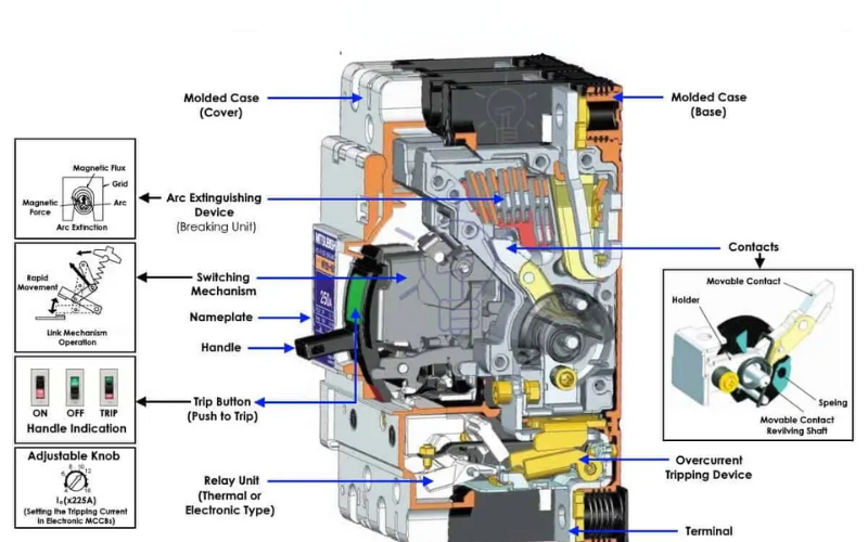
Immagine che mostra la complessa architettura interna di un MCCB standard.

Il meccanismo di funzionamento meccanico è responsabile della rapida separazione dei contatti quando viene attivato un intervento.
Suggerimento per i professionisti: Il valore del potere di interruzione (Icu o Ics) indicato su un interruttore magnetotermico non è un suggerimento. È la corrente di guasto massima assoluta che l'interruttore è certificato per interrompere senza esplodere. Assicurarsi sempre che il valore nominale dell'interruttore superi la corrente di guasto calcolata disponibile nella sua posizione, con un margine di sicurezza di 25% per future modifiche al sistema. .
Un errore comune e pericoloso consiste nel ritenere che qualsiasi interruttore automatico possa funzionare su qualsiasi circuito. La fisica dell'interruzione della corrente alternata (CA) e della corrente continua (CC) è fondamentalmente diversa e l'uso dell'interruttore sbagliato può avere conseguenze disastrose.
In un sistema a corrente alternata, la corrente passa naturalmente attraverso lo zero 100 o 120 volte al secondo (a 50/60 Hz). Questo punto di “attraversamento dello zero” costituisce un momento di assistenza naturale per lo spegnimento dell'arco elettrico. L'arco perde energia ed è più facile da spegnere.
In un sistema a corrente continua, la corrente è costante. Non c'è attraversamento dello zero. Un arco, una volta formatosi, si manterrà felicemente finché ci sarà una tensione sufficiente, rendendo molto più difficile il suo spegnimento. Questo richiede un approccio progettuale completamente diverso.
Ecco una panoramica delle principali differenze:
| Caratteristica | MCCB CA | MCCB DC |
|---|---|---|
| Metodo di estinzione ad arco | Si basa sull'attraversamento di zero corrente e su uno scivolo ad arco standard con piastre metalliche. | Richiede l'estinzione forzata dell'arco. Utilizza bobine magnetiche “blow-out” per allungare l'arco e scivoli ad arco multiplo più grandi e complessi. |
| Materiali di contatto | Leghe di argento-nichel o argento-grafite, ottimizzate per la conduttività e l'usura standard dell'arco. | Leghe a base di argento con tungsteno o altri metalli duri per resistere alla maggiore energia e alla durata prolungata di un arco CC. |
| Valori di tensione | In genere, la tensione nominale è fino a 690 V CA. Un interruttore tripolare con tensione nominale di 480 V CA potrebbe essere dimensionato solo per 250 V CC. | Specificato per la tensione CC, spesso fino a 1500 V CC per applicazioni come i sistemi solari fotovoltaici (PV). |
| Applicazioni tipiche | Distribuzione degli edifici, controllo dei motori industriali, sistemi di alimentazione commerciali. | Sistemi di energia solare, sistemi di accumulo di energia a batteria (BESS), trasporto ferroviario, distribuzione di energia CC nei centri dati. |
| Considerazioni sui test | Testato in base ai parametri di guasto CA (fattore di potenza). | Testato con una specifica costante di tempo (rapporto L/R, ad esempio T=4ms o 15ms) che simula l'induttanza di un circuito CC. |
Il risultato principale: Non utilizzare mai un interruttore magnetotermico in c.a. in un'applicazione in c.c., a meno che non sia esplicitamente contrassegnato dal produttore con una classificazione in c.c.. Il sistema di spegnimento dell'arco in un interruttore standard in c.a. non è progettato per gestire l'energia continua di un arco di guasto in c.c. e probabilmente non funzionerà in modo sicuro.
Un MCCB può rimanere inattivo per anni e poi essere chiamato a funzionare in pochi millisecondi. Fidarsi del suo funzionamento senza alcuna verifica è una negligenza. Un robusto programma di test assicura che rimanga un protettore affidabile. Quindi, come si esegue il test MCCB procedure vengono eseguite correttamente sul campo? Seguiamo un processo strutturato in 6 fasi basato sulle migliori pratiche del settore. .
Prima di qualsiasi test elettrico, iniziate con gli occhi e le mani. Questo semplice passo può prevenire guasti catastrofici.
Questo test verifica l'integrità dell'isolamento dell'interruttore magnetotermico, assicurando che non vi siano dispersioni di corrente tra i poli o verso terra.
Questo test misura la resistenza dei contatti principali che trasportano la corrente all'interno dell'interruttore. Una resistenza elevata indica contatti bucati, corrosi o disallineati, che causano un surriscaldamento sotto carico.
Suggerimento per i professionisti: Eseguire sempre il test della resistenza di contatto prima il test di intervento per sovracorrente. Il test di intervento riscalda i componenti interni e ciò altera le letture della resistenza di contatto. Se è necessario eseguire il test dopo, lasciare raffreddare l'interruttore per almeno 20 minuti.
È il test più critico. Assicura che le funzioni di sgancio termico e magnetico funzionino secondo le specifiche. Questo test richiede un set di prova specializzato per le alte correnti.
Per gli interruttori automatici con unità di sgancio elettroniche, questo test verifica lo stato di salute dell'elettronica dell'unità di sgancio senza la necessità di iniettare corrente elevata. Molti set di prova moderni possono interfacciarsi direttamente con l'unità di sgancio dell'interruttore per simulare guasti e confermare che l'unità invia un segnale di sgancio al meccanismo. Si tratta di un modo rapido ed efficace per testare il “cervello” dell'interruttore.
Questo test è fondamentale per garantire la sicurezza complessiva del circuito, non solo dell'interruttore stesso. Verifica che se si verifica un guasto tra un conduttore sotto tensione e la terra, la corrente risultante sia sufficientemente elevata da far scattare l'interruttore magnetotermico entro il tempo richiesto. Un'elevata impedenza di loop può impedire l'intervento dell'interruttore, creando una situazione pericolosa in cui i componenti metallici possono diventare sotto tensione senza che il guasto venga eliminato.
I test sul campo non sono arbitrari, ma sono guidati da solidi standard industriali che garantiscono coerenza e affidabilità. I due standard più importanti per gli MCCB sono:
Anche con un buon programma di test, possono sorgere dei problemi. Ecco alcuni problemi comuni e come affrontarli:
L'interruttore automatico scatolato è una straordinaria opera di ingegneria, progettata per proteggere dalla distruzione i nostri sistemi elettrici più critici. Ma come ogni dispositivo di sicurezza, è affidabile solo in base alle sue condizioni. Pensare che funzionerà per sempre è una ricetta per tempi di inattività non pianificati e potenziali disastri.
Comprendendo il funzionamento di un interruttore magnetotermico, rispettando le differenze tra applicazioni in c.a. e c.c. e implementando una solida struttura di test basata su standard, si trasforma l'interruttore da un potenziale problema a una risorsa verificata e affidabile. La risposta a “come si esegue il test MCCB”Non si tratta di una singola procedura, ma di un approccio completo alla manutenzione che garantisce la protezione quando è più necessaria. Non aspettate la telefonata delle 3 del mattino per scoprire che le vostre difese hanno fallito.
1. Con quale frequenza devono essere testati gli MCCB?
Per le applicazioni critiche come ospedali o centri dati, gli standard NETA/NEMA raccomandano di eseguire i test ogni 1-3 anni. Per le applicazioni industriali meno critiche, è comune un intervallo da 3 a 5 anni. La frequenza deve essere regolata in base all'età dell'interruttore, all'ambiente (ad esempio, polveroso o corrosivo) e alla criticità.
2. È possibile utilizzare un MCCB in CA per un'applicazione solare in CC?
No, a meno che non sia esplicitamente classificato come doppio dal produttore con una tensione CC e un potere di interruzione specifici. Un MCCB standard in c.a. probabilmente non riuscirà a estinguere un arco di guasto in c.c. in modo sicuro. .
3. Qual è la differenza tra le classificazioni Icu e Ics?
4. Il mio MCCB è caldo al tatto. È normale?
Un interruttore che trasporta una porzione significativa del suo carico nominale si sentirà caldo a causa delle perdite I²R, il che è normale. Tuttavia, se la sensazione di calore è eccessiva o se il calore si concentra sui terminali, indica un problema come un collegamento allentato o un'elevata resistenza di contatto che deve essere immediatamente indagato.
5. Che cos'è un MCCB “a limitazione di corrente”?
Un interruttore magnetotermico a limitazione di corrente utilizza uno speciale design dei contatti ad alta repulsione che, in caso di guasto di alto livello, li separa con estrema rapidità (in 1/4 di ciclo o meno). Questo interrompe la corrente prima che possa raggiungere il suo picco potenziale, riducendo significativamente la quantità di energia distruttiva lasciata passare alle apparecchiature a valle. .
6. Perché il mio interruttore a valle è scattato ma non l'MCCB principale?
Questo è ciò che idealmente dovrebbe accadere. Si chiama coordinamento selettivo. Il sistema è progettato in modo che il dispositivo di protezione più vicino al guasto si apra per primo, riducendo al minimo l'entità dell'interruzione di corrente. Se l'interruttore principale scatta insieme a quello a valle, indica un guasto di coordinamento. .
7. È possibile riparare un MCCB sigillato?
No. Se un MCCB con involucro sigillato non supera un test elettrico o presenta un meccanismo difettoso, deve essere sostituito. L'apertura di un involucro sigillato invalida le certificazioni di sicurezza (come l'elenco UL) e ne rende insicuro l'uso. .
8. Un maggior carico di rottura è sempre meglio?
Sì, dal punto di vista della sicurezza, un potere di interruzione più elevato offre un margine di sicurezza maggiore. Tuttavia, gli interruttori con valori nominali estremamente elevati sono più costosi. L'approccio corretto consiste nell'eseguire uno studio della corrente di guasto per determinare la corrente di guasto disponibile nella posizione dell'interruttore e scegliere un interruttore che superi in modo sicuro tale valore, bilanciando sicurezza e costi.
