Zone industrielle WengYang Yueqing Wenzhou 325000
Heures de travail
Du lundi au vendredi : de 7h00 à 19h00
Le week-end : 10H00 - 17H00
Zone industrielle WengYang Yueqing Wenzhou 325000
Heures de travail
Du lundi au vendredi : de 7h00 à 19h00
Le week-end : 10H00 - 17H00
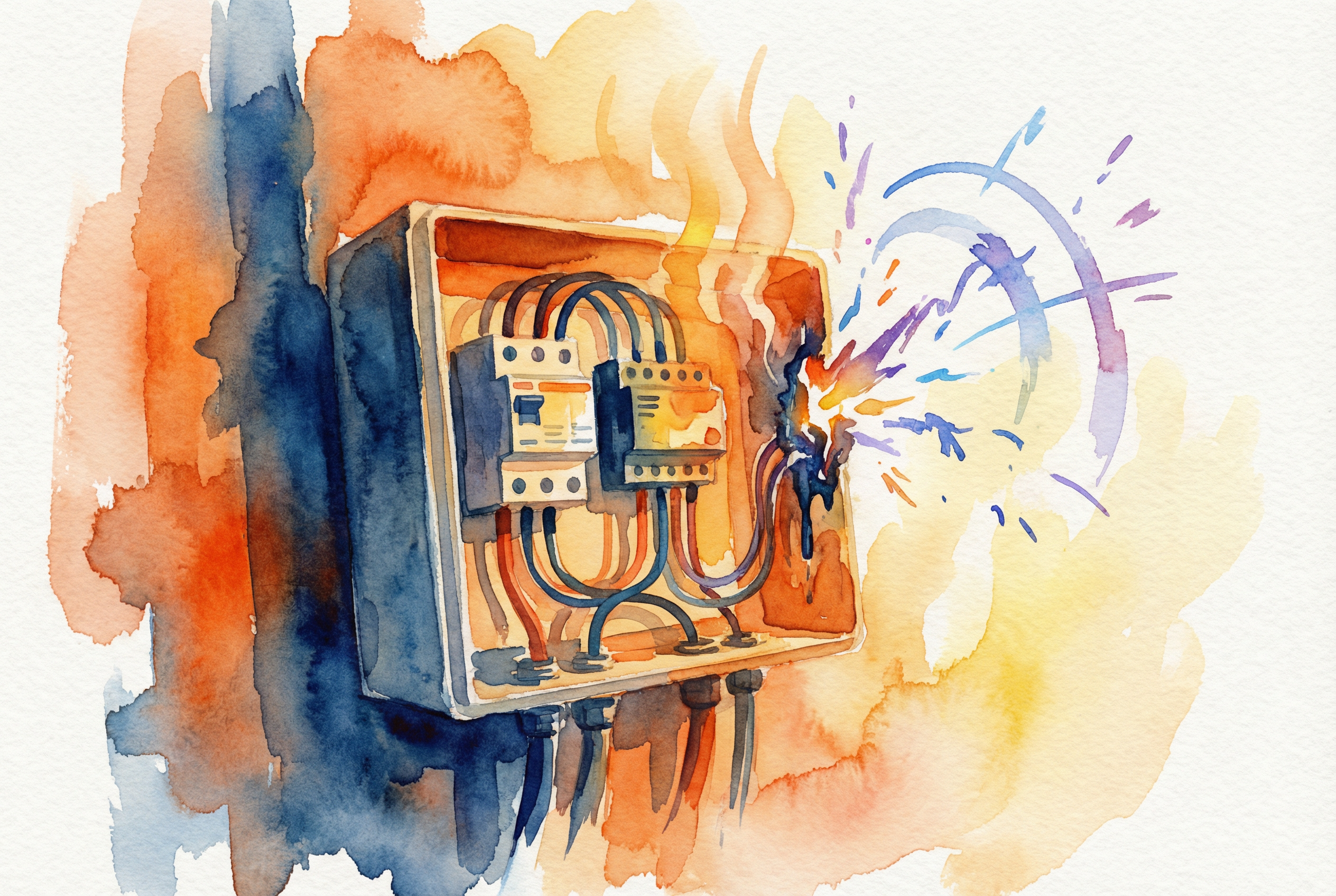
L'appel est arrivé un lundi matin, le genre d'appel que tout ingénieur électricien redoute. Un système commercial de 100 kW installé sur un toit, mis en service six mois auparavant, était mort. Le responsable du site a décrit une “odeur de plastique brûlé” qui s'échappait de la boîte de combinaison CC principale. Lorsque je suis arrivé sur place, la cause n'était pas un composant défectueux ou un coup de foudre. L'intérieur de la boîte de raccordement était carbonisé et fondu parce qu'un disjoncteur de courant continu haut de gamme avait inversé ses connexions de ligne et de charge.
Depuis plus de 15 ans que je suis ingénieur d'application principal dans l'industrie de l'automatisation électrique, j'ai analysé d'innombrables défaillances de systèmes. La dure vérité est que la plupart des problèmes catastrophiques côté courant continu ne sont pas causés par un équipement bon marché, mais par erreurs de câblage de la protection c.c..
Contrairement au courant alternatif (CA), qui pardonne grâce à sa nature de passage à zéro, le courant continu (CC) est implacable. C'est un flux continu d'énergie qui, s'il est mal géré, devient un risque d'incendie en quelques millisecondes. Ce guide est né de ces leçons de terrain durement acquises. Nous allons passer en revue les 10 principales erreurs que j'ai constatées sur le terrain et fournir les cadres d'ingénierie exploitables dont vous avez besoin pour les éviter.
Il s'agit sans aucun doute de l'erreur la plus fréquente et la plus dangereuse dans les installations à courant continu.
Le problème :
Dans les circuits à courant alternatif, le courant change de direction 100 ou 120 fois par seconde. Dans les circuits à courant continu, le courant circule dans un seul sens. De nombreux disjoncteurs à courant continu très performants sont “polarisés”. Ils contiennent des aimants permanents conçus pour repousser l'arc électrique. en la goulotte d'extinction de l'arc lorsque le disjoncteur se déclenche.
Si vous les câblez à l'envers (en intervertissant la ligne et la charge), le champ magnétique interne tirera l'arc vers le haut. à l'extérieur de la goulotte et dans les composants mécaniques délicats du disjoncteur. Au lieu de s'éteindre, l'arc se maintient, faisant fondre le disjoncteur et risquant d'enflammer le boîtier.
La solution :
+ et - symboles ou LIGNE et CHARGER sur l'appareil.![Image : Gros plan d'un disjoncteur à courant continu montrant clairement la polarité (+/-) et les marquages Ligne/Charge].
Ce qu'il faut retenir : Pour les disjoncteurs à courant continu polarisés, la polarité correcte n'est pas une suggestion, c'est une exigence pour que la physique de l'extinction de l'arc fonctionne. Vérifiez toujours la polarité à l'aide d'un multimètre avant de mettre l'appareil sous tension.
Une connexion sécurisée est une connexion sûre. Malheureusement, la méthode de serrage à la main “bon et serré” est une recette pour une défaillance thermique.
Le problème :
La solution :
Adoptez une politique de “tolérance zéro” pour les connexions non serrées. Vous devez utiliser un tournevis dynamométrique calibré.
Conseil de pro : la méthode “marquer et déplacer
Après avoir appliqué le couple spécifié par le fabricant (généralement imprimé sur le côté du rupteur en N-m ou lb-in), appliquez un point de “torque seal” ou de laque d'inspecteur sur la vis et le boîtier. Cela permet de prouver visuellement que le travail a été effectué et de repérer facilement si une vis s'est desserrée par vibration lors d'inspections ultérieures.
![Image : Un technicien utilisant un tournevis dynamométrique jaune calibré sur une borne CC, appliquant une peinture d'étanchéité au couple].
Utiliser un disjoncteur à courant alternatif dans un circuit à courant continu revient à essayer d'arrêter un train de marchandises en marche avec des freins de bicyclette.
Le problème :
Le courant alternatif traverse naturellement le zéro volt plus de 100 fois par seconde. Un disjoncteur CA compte sur ce “passage par zéro” pour éteindre l'arc. Le courant continu n'a pas de passage par zéro. Si vous utilisez un disjoncteur à courant alternatif sur une chaîne à courant continu de 600 V, le disjoncteur pourra s'ouvrir, mais l'arc électrique pontera les contacts, continuant à brûler jusqu'à ce que l'appareil soit détruit.
Tableau 1 : Spécifications des disjoncteurs en courant alternatif et en courant continu
| Fonctionnalité | Disjoncteur CA standard | Disjoncteur à courant continu | Pourquoi c'est important pour la protection du courant continu |
|---|---|---|---|
| Trempe à l'arc | Reliance sans croisement | Eclatements magnétiques et chutes d'arc | Les arcs en courant continu sont continus ; ils doivent être physiquement étirés et refroidis pour s'arrêter. |
| Contact Gap | Plus petit | Une taille nettement plus importante | Des écarts plus importants sont nécessaires pour rompre l'arc en courant continu. |
| Polarisation | Non polarisé | Souvent polarisés | Des aimants directionnels guident l'arc dans la goulotte. |
| Taux d'interruption | Valeur nominale en ampères CA | Valeur nominale en ampères CC | Les valeurs nominales en courant alternatif sont les suivantes invalide pour les applications en courant continu. |
La solution :
Ne jamais se fier à l'adaptation physique du disjoncteur (par exemple, montage sur rail DIN). Vérifiez toujours que la fiche technique indique explicitement l'emplacement de l'interrupteur. Tension nominale en courant continu et Capacité d'interruption en courant continu.
Le dimensionnement de la protection CC ne consiste pas seulement à faire correspondre l'ampacité du fil, mais aussi à adhérer à la “règle 125%” et à prendre en compte le service continu.
Le problème :
L'article 690.8 du NEC exige que les courants des circuits solaires soient considérés comme “continus”. Cela signifie que les conducteurs et les dispositifs de protection contre les surintensités (OCPD) doivent être dimensionnés à 125% du courant maximal calculé du circuit. Si vous avez une chaîne avec un Isc (courant de court-circuit) de 10A, vous ne pouvez pas utiliser un fusible de 10A. Il finira par s'user et se déclenchera de manière intempestive en raison de la contrainte thermique.
La solution :
Suivez cette méthode de sélection en 3 étapes :
Tableau 2 : Exemple de calcul du dimensionnement des fusibles gPV
| Paramètres | Valeur | Calcul / Logique |
|---|---|---|
| Module Isc | 12A | A partir de la fiche technique du panneau solaire |
| Facteur de sécurité | 1.25 | Exigence de service continu du NEC |
| Valeur minimale du fusible | 15A | $12A \ fois 1,25 = 15A$ |
| Déclassement en fonction de la température ambiante | 0.90 | Suppose une température interne de la boîte de 50°C |
| Sélection finale des fusibles | 20A | Un fusible de 15A déclassé de 0,90 n'est que de 13,5A (trop proche de l'Isc). Augmenter le fusible à 20A pour éviter les déclenchements intempestifs. |
Les dispositifs de protection contre les surtensions (SPD) sont essentiels, mais leur efficacité est dictée par la physique, en particulier l'inductance.
Le problème :
L'inductance d'un fil résiste aux variations de courant. La foudre provoque une variation massive et instantanée du courant ($di/dt$). Selon la formule $V = L \ fois (di/dt)$, même une petite longueur de fil ($L$) crée une chute de tension massive ($V$) lors d'une surtension. Si vos fils SPD sont longs et enroulés, la pointe de tension contournera le SPD et ira directement dans votre onduleur, rendant la protection inutile.
La solution :
Garder des pistes court et droit. Éviter les coudes à 90 degrés.
Mermaid Diagramme 1 : Câblage SPD correct ou incorrect
Principaux enseignements : Chaque centimètre de fil ajoute une inductance. La connexion d'un dispositif de protection contre les surtensions avec un mètre de fil le déconnecte effectivement lors d'une surtension à montée rapide.
L'utilisation de fils de construction standard (THHN) sur un toit est une bombe à retardement.
Le problème :
Les câbles CC des panneaux solaires sont exposés à des rayons UV extrêmes, à des variations de température (du gel à la cuisson) et à l'humidité. L'isolation en PVC standard se fissure et s'écaille après quelques années d'exposition aux UV, ce qui entraîne des défauts de mise à la terre dangereux et des arcs électriques potentiels.
La solution :
![Image : Une installation solaire professionnelle montrant une gestion soignée des câbles, avec des fils fixés au rayonnage à l'aide d'attaches métalliques, sans tomber].
Le respect du code concernant les déconnexions vise principalement à assurer la sécurité des premiers intervenants.
Le problème :
L'article 690.13 du NEC exige une déconnexion “facilement accessible”. Le fait de cacher un interrupteur à l'intérieur d'une boîte de raccordement verrouillée dont l'ouverture nécessite un tournevis, ou de le placer sur un toit dont l'accès nécessite une échelle portative, constitue une violation de cette règle. Si un pompier ne trouve pas l'interrupteur ou ne peut pas l'atteindre en toute sécurité, il ne peut pas mettre le système hors tension.
La solution :
Un fusible calibré pour 20A à 25°C ne tient pas 20A à 60°C.
Le problème :
Les boîtes de combinaisons installées sur les toits se transforment en fours. Les températures internes peuvent facilement dépasser 60°C (140°F). À mesure que la température augmente, l'élément métallique à l'intérieur d'un fusible ou d'un disjoncteur magnétothermique se ramollit, ce qui entraîne son déclenchement à un courant inférieur à sa valeur nominale. Il en résulte des “déclenchements fantômes”, c'est-à-dire que le système s'arrête pendant les journées chaudes, au moment même où la production solaire devrait être la plus élevée.
Tableau 3 : Facteurs de déclassement typiques de l'ampacité des câbles (fils à 90°C)
| Température ambiante (°C) | Température ambiante (°F) | Facteur de correction | Impact sur le câble 40A |
|---|---|---|---|
| 36-40 | 97-104 | 0.91 | 36.4A |
| 46-50 | 114-122 | 0.82 | 32.8A |
| 56-60 | 132-140 | 0.71 | 28.4A |
| 66-70 | 151-158 | 0.58 | 23.2A |
La solution :
Appliquez toujours les facteurs de correction de la température indiqués sur la fiche technique du fabricant ou dans le tableau 310.15(B)(2)(a) du NEC. Si votre boîtier est exposé au soleil, supposez une température interne d'au moins + 15°C.
Lorsqu'un défaut se produit, seul l'appareil le plus proche du défaut doit se déclencher. C'est ce qu'on appelle la “sélectivité”.”
Le problème :
Si vous avez un fusible de 15 A au niveau de la branche et un disjoncteur de 20 A à la sortie du combineur, un défaut sur une branche peut déclencher le disjoncteur principal au lieu de faire sauter le fusible de la branche. Cela met hors service l'ensemble du réseau au lieu d'une seule branche.
La solution :
Veiller à ce qu'il y ait un rapport suffisant entre les dispositifs en amont et en aval. Utiliser les courbes temps-courant (TCC) pour vérifier que l'appareil en aval élimine le défaut avant que l'appareil en amont ne se désenclenche.
Tableau 4 : Méthodes de protection pour différentes conditions de défaut
| Type d'erreur | Caractéristiques | Dispositif recommandé | Temps de réponse |
|---|---|---|---|
| Surcharge | 101-200% courant (montée lente) | Disjoncteur DC magnéto-thermique | Des secondes aux minutes |
| Court-circuit | 10-20x le courant (pic instantané) | gPV Fusible ou disjoncteur magnétique | <10ms |
| Défaut à la terre | Fuite de courant vers la terre | GFDI / RCD | <100ms |
Ce n'est pas parce qu'il s'agit de DC qu'il ne risque pas d'exploser.
Le problème :
Les arcs en courant continu sont plus chauds et durent plus longtemps que les arcs en courant alternatif. Un éclair d'arc dans un grand banc de batteries ou un combinateur solaire de 1500 V peut dégager des températures supérieures à 20 000°C. Les ingénieurs calculent souvent les limites de l'éclair d'arc pour l'appareillage de commutation à courant alternatif, mais ignorent le côté à courant continu.
La solution :
![Image : Technicien portant l'EPI approprié pour l'éclair d'arc électrique travaillant sur une boîte de combinateur CC commerciale].
Pour que votre système soit sûr et assurable, vous devez utiliser des composants certifiés selon la norme appropriée. L'utilisation d'un composant UL dans un projet européen IEC (ou vice versa) peut parfois conduire à des échecs d'inspection si les références croisées ne sont pas correctes.
Tableau 5 : Normes de certification CEI vs. UL
| Spécifications | IEC 60269-6 (Global) | UL 2579 (Amérique du Nord) |
|---|---|---|
| Champ d'application | Fusibles spécifiques au PV (gPV) | Fusibles pour systèmes photovoltaïques |
| Constante de temps | 5ms à 15ms | 5ms à 12ms |
| Tension nominale | 600V, 1000V, 1500V DC | 300V, 600V, 1000V, 1500V DC |
| Capacité de rupture | 10kA, 20kA, 30kA | 10kA, 15kA, 20kA, 30kA |
| Approche des tests | Paramètres de performance | Sécurité au niveau du système et alignement des CNE |
Q : Puis-je utiliser un fusible CA standard dans mon boîte de raccordement solaire?
A : Absolument pas. Les fusibles à courant alternatif ne sont pas conçus pour étouffer un arc à courant continu. L'utilisation d'un fusible à courant alternatif présente un risque d'incendie grave. Recherchez toujours l'indice “gPV” ou l'homologation UL 2579.
Q : Pourquoi mes disjoncteurs DC ne cessent-ils de se déclencher pendant les après-midi chauds ?
A : Cela est probablement dû à un déclassement thermique. Si la température ambiante à l'intérieur de l'armoire est élevée, l'élément thermique du disjoncteur se dilate, ce qui abaisse son seuil de déclenchement. Vérifiez vos calculs de dimensionnement et appliquez le facteur de correction de température correct.
Q : Ai-je vraiment besoin d'un tournevis dynamométrique ? Ma main semble calibrée.
A : Oui, vous en avez besoin. La perception humaine du couple est notoirement inexacte. Un serrage insuffisant est source de chaleur et d'incendie ; un serrage excessif est source de rupture mécanique. C'est un petit investissement pour la sécurité du système.
Q : Quelle est la différence entre une déconnexion avec rupture de charge et une déconnexion sans rupture de charge ?
A : Un dispositif de coupure en charge est conçu pour interrompre en toute sécurité la totalité du courant électrique. Un interrupteur sans coupure en charge (isolateur) ne doit être ouvert qu'après l'arrêt du courant (par exemple, par l'onduleur). L'ouverture d'un interrupteur sans coupure en charge provoque un arc électrique dangereux.
Le câblage correct des systèmes de protection à courant continu consiste à respecter la physique du courant continu. Il ne s'agit pas simplement de connecter des fils, mais de comprendre en profondeur la polarité, la température, l'inductance et le comportement de l'arc électrique.
En évitant ces 10 erreurs courantes, vous ne vous contentez pas de cocher des cases sur un formulaire d'inspection ; vous assurez la longévité de votre investissement et la sécurité des personnes qui l'entretiennent.
