Zone industrielle WengYang Yueqing Wenzhou 325000
Heures de travail
Du lundi au vendredi : de 7h00 à 19h00
Le week-end : 10H00 - 17H00
Zone industrielle WengYang Yueqing Wenzhou 325000
Heures de travail
Du lundi au vendredi : de 7h00 à 19h00
Le week-end : 10H00 - 17H00
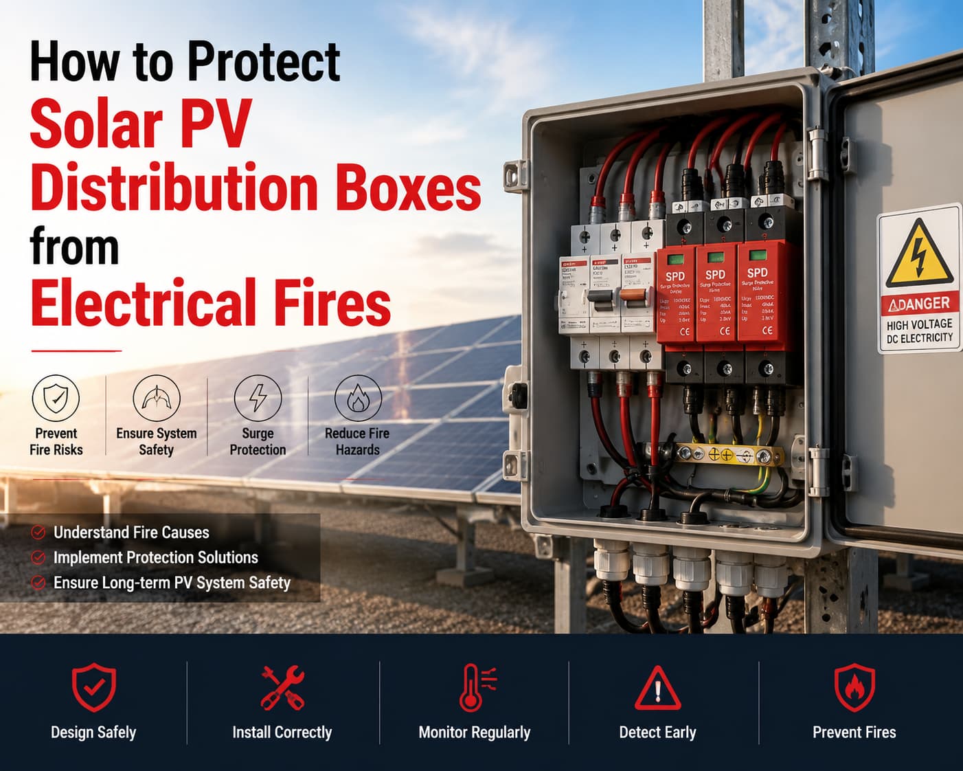
Solar PV systems are widely deployed across residential, commercial, and utility-scale projects. However, electrical fire risks remain concentrated in one critical area: the PV distribution box (combiner box / string distribution enclosure).
Most fire incidents do not originate from PV modules or inverters. Instead, they begin inside distribution boxes due to DC arc faults, loose connections, surge events, or thermal accumulation.
This article explains:
The goal is not theoretical safety discussion, but practical engineering guidance for EPC contractors, system designers, and PV operators.
In a solar PV system, the distribution box serves as the central aggregation and protection node for DC strings. It is exposed to continuous electrical load and environmental stress, often for more than 20 years.
Unlike AC distribution systems, PV distribution boxes operate under high-voltage DC conditions (600V–1500V), where faults behave differently and are harder to interrupt.
| Fonction | Description | Fire Risk Contribution |
|---|---|---|
| String aggregation | Combines multiple PV strings | High current concentration |
| Protection contre les surintensités | Fuse / breaker integration | Heat generation under fault |
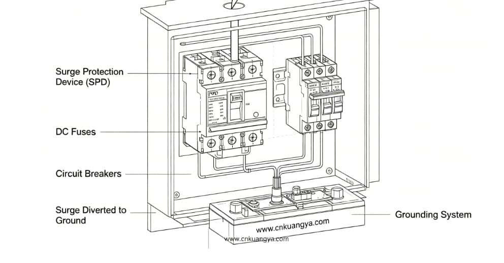
| Protection contre les surtensions | SPD integration | Lightning energy exposure |
| Field isolation | DC disconnect function | Mechanical wear risk |
| Monitoring interface | Optional sensors | Detection dependency |
Each function adds complexity, and complexity increases failure probability.
Field investigation reports from EPC contractors and insurance assessments consistently show:
The main reason is simple:
The distribution box is where mechanical connection + electrical load + environmental exposure intersect.
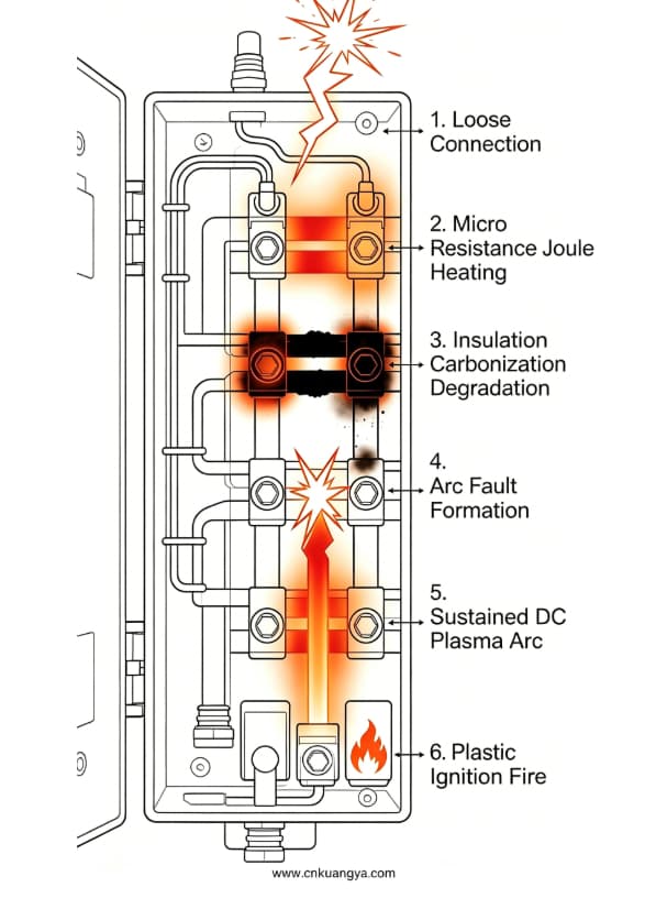
Most PV fire events are not sudden. They follow a progressive degradation model that often lasts weeks or months before ignition.
Understanding this progression is essential for effective Solar Electrical Fire Prevention.
| Stade | Electrical Condition | Physical Effect | Detectability |
|---|---|---|---|
| 1 | Slight loose connection | Micro resistance increase | Très faible |
| 2 | Local heating begins | Temperature rise (20–80°C) | Faible |
| 3 | Vieillissement de l'isolation | Material discoloration | Moyen |
| 4 | Partial arcing | Intermittent discharge | Sometimes detectable |
| 5 | DC sustained arc | Extreme heat (>1000°C) | High risk stage |
| 6 | Ignition | Cable or enclosure fire | Visible failure |
The most dangerous aspect is that Stages 1–3 are invisible in normal operation.
In DC systems, even a very small resistance increase can create significant heat:
These conditions may not trip protection devices immediately, allowing heat accumulation to continue.
This is why PV fire risk is often described as a “hidden degradation process” rather than an instant failure.”
Although manufacturers rarely publish failure data, EPC contractors and insurance investigations provide consistent patterns across global projects.
| Project Type | Location Environment | Cause première | Résultats |
|---|---|---|---|
| Utility-scale solar farm | Desert (Middle East) | Terminal overheating in combiner box | String shutdown + replacement cost |
| Industrial rooftop PV | Factory environment | Loose MC4 connection inside distribution box | Roof fire spread |
| Coastal solar installation | Humid region | Corrosion inside enclosure | Progressive short circuit |
| High-lightning zone plant | Asie du Sud-Est | SPD failure after surge event | Inverter + box damage |
Across all scenarios, one pattern remains consistent:
The ignition point is rarely the main equipment. It is almost always a connection or protection interface inside the distribution box.
PV fire risk is significantly influenced by environment:
| Environnement | Risk Mechanism |
|---|---|
| Desert | Thermal expansion → terminal loosening |
| Coastal | Salt corrosion → resistance increase |
| Tropical | Moisture ingress → leakage current |
| High altitude | UV degradation of insulation |
| Lightning zones | Surge stress on SPD system |
Understanding DC behavior is essential in Distribution Box Fire Protection design.
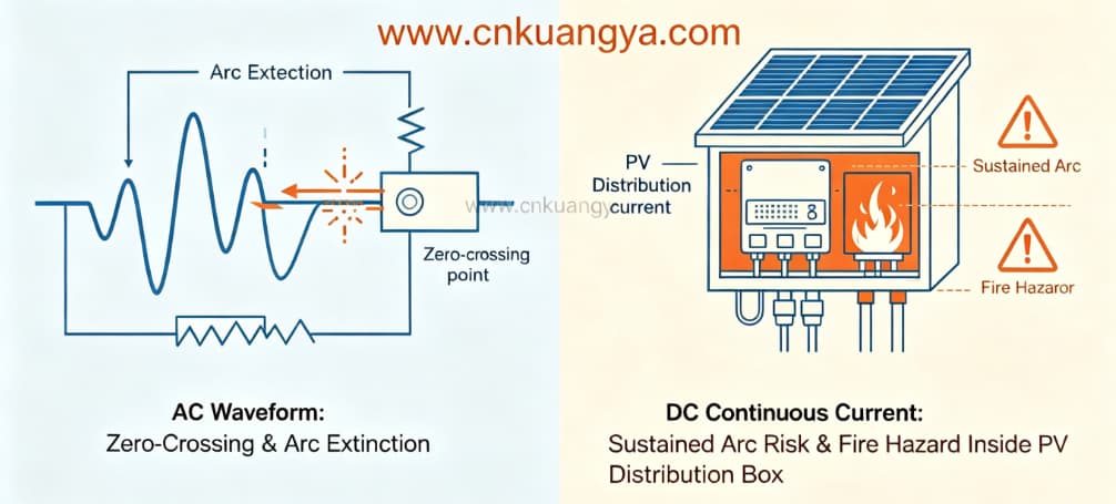
| Fonctionnalité | AC System | PV DC System |
|---|---|---|
| Current zero-crossing | Oui | Non |
| Arc extinction | Natural | Requires intervention |
| Fault interruption | Plus facile | Difficile |
| Heat accumulation | Intermittent | Continu |
| Fire propagation speed | Plus lent | Faster |
In AC systems, the current naturally drops to zero multiple times per second, helping extinguish arcs.
In DC systems used in solar PV, current is continuous. Once an arc forms, it sustains itself until interrupted mechanically or electrically.
This is one of the most important reasons why PV systems require multi-layer fire protection architecture.
Overcurrent protection is another key factor in preventing thermal accumulation inside PV distribution boxes. Properly selected Fusibles DC ensure string-level fault isolation and reduce the risk of sustained overheating in high-current conditions.
PV fire incidents are usually caused by a combination of factors rather than a single failure.
In most failure investigations, engineers rarely find a single root cause. Instead, they identify:
a combination of minor defects that gradually created a high-resistance hotspot.
Before ignition occurs, PV distribution boxes often show subtle warning signs.
| Warning Sign | Technical Meaning |
|---|---|
| Slight discoloration | Local overheating |
| Burning smell | Dégradation de l'isolation |
| Intermittent inverter alarms | Arc or voltage fluctuation |
| SPD indicator change | Surge exposure |
| Higher thermal reading on one string | Uneven resistance |
Most of these signals are ignored during routine operation because systems continue to function normally.
This creates a false sense of safety.
At this stage, understanding risk is not enough. The system must be designed to interrupt failure progression at multiple points.
Moderne Solar PV Fire Protection design follows a layered approach:
Each layer is responsible for stopping a different stage of failure development.
A large portion of PV fire risk is determined not during operation, but during the design and manufacturing stage of the distribution box.
Even if high-quality components are used, poor enclosure design or internal layout can still create overheating zones and electrical instability.
In EPC practice, distribution box safety is usually judged by five critical design factors.
PV system design and installation safety should comply with international standards for photovoltaic arrays, especially regarding DC system protection and wiring safety requirements according to IEC 62548 photovoltaic system design standard.
| Design Element | Recommended Standard | Fire Risk if Ignored |
|---|---|---|
| Enclosure rating | IP65–IP66 outdoor grade | Moisture ingress → short circuit |
| Material type | Flame-retardant PC or metal enclosure | Fire propagation inside box |
| Internal layout | Separated DC string routing | Heat concentration zones |
| Thermal design | Passive or active ventilation | Internal temperature buildup |
| Terminal system | Torque-controlled connectors | Long-term resistance heating |
One of the most underestimated design issues is internal heat accumulation.
In many PV systems, distribution boxes are fully sealed to protect against dust and rain. However, without thermal dissipation design, internal temperature can exceed safe operating limits during peak sunlight hours.
This creates a condition where:
ambient temperature + electrical loss = long-term thermal stress accumulation
Over time, this significantly increases fire probability.
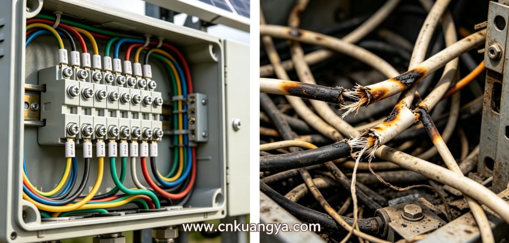
Field studies across EPC projects show a consistent pattern:
A significant percentage of PV fires originate from installation errors rather than component defects.
Even premium equipment cannot compensate for poor installation practices.
Improper torque application is one of the most common causes of long-term heating.
Both conditions increase thermal loss.
Inside distribution boxes, cable congestion creates localized heat zones.
Poor routing can lead to:
Incorrect string connection may not cause immediate failure, but it can:
Improper grounding is especially dangerous in lightning-prone regions.
Without proper earthing:
| Installation Area | Erreur courante | Fire Impact |
|---|---|---|
| Terminaux | No torque control | Long-term overheating |
| Câblage | Overcrowded layout | Heat concentration |
| Mise à la terre | Incomplete earthing | Surge accumulation |
| Essais | Skipped commissioning checks | Hidden faults remain |
PV systems are designed for long operational lifetimes (20–25 years), but electrical connections degrade continuously over time.
Without maintenance, even a perfectly installed system will eventually develop risks.
| Interval | Inspection Focus | Objectif |
|---|---|---|
| Mensuel | Inspection visuelle | Detect discoloration or odor |
| Trimestrielle | Thermal imaging scan | Identify hotspot development |
| Biannual | Terminal torque verification | Prevent loosening over time |
| Annual | SPD condition check | Ensure surge protection integrity |
| 3–5 years | Component replacement review | Prevent aging-related failure |
Infrared thermography is one of the most effective tools in Solar Electrical Fire Prevention.
It allows detection of:
Most importantly, it detects problems before physical damage occurs.
In PV systems, surge events are one of the most underestimated fire triggers.
Lightning strikes or switching surges can introduce extremely high transient voltage into the system. If not properly managed, this energy can directly damage insulation inside distribution boxes.
| Fonction | Fire Protection Effect |
|---|---|
| Voltage clamping | Prevents insulation breakdown |
| Surge diversion | Redirects energy to grounding system |
| Protection thermique | Reduces heat stress on components |
| System stabilization | Avoids transient arc initiation |
SPD failure is often not immediate. It degrades over time after repeated surge exposure.
If not replaced or monitored, it becomes a silent risk factor.
This is why SPD coordination is a core part of Distribution Box Fire Protection strategy, not just a supplementary device.
Modern PV systems are gradually shifting from passive protection to active intelligent protection.
Detects abnormal DC waveform patterns and disconnects the circuit before ignition occurs.
Provides real-time temperature tracking across multiple distribution boxes in a PV plant.
Designed for enclosed electrical spaces, these systems activate automatically when temperature reaches ignition thresholds.
Unlike traditional suppression methods, aerosol systems:
Enable remote isolation of faulty strings or boxes during emergency conditions.
In high-value EPC projects, especially utility-scale solar farms, there is a clear shift toward:
“early detection + automatic suppression + remote isolation”
This reduces dependence on manual intervention, which is often too slow in DC fire scenarios.
A modern PV fire protection strategy is not based on a single device, but on a multi-layer integrated system.
| Couche | Fonction | System Component |
|---|---|---|
| Detection layer | Identify abnormal behavior | Sensors, AFCI systems |
| Control layer | Analyze and respond | Monitoring controller |
| Protection layer | Interrupt fault current | Fuse, breaker, SPD |
| Isolation layer | Disconnect system | DC isolator switch |
| Suppression layer | Fire extinction | Aerosol system |
The key principle is redundancy:
If one layer fails, another must still prevent fire escalation.
This layered architecture is now considered standard practice in high-end EPC solar projects.
Despite available technology, many PV fire incidents still occur due to avoidable mistakes.
| Erreur | Conséquence |
|---|---|
| Ignoring torque standards | Long-term overheating at terminals |
| Undersized SPD selection | Surge breakdown inside enclosure |
| Poor enclosure sealing | Moisture-induced short circuits |
| Lack of thermal inspection | Undetected hotspot development |
| No maintenance plan | Progressive system degradation |
Most PV fires are not caused by sudden failure.
They are caused by:
“small issues accumulating over time until system tolerance is exceeded.”
Protecting solar PV distribution boxes from electrical fires requires a combination of:
In real EPC environments, fire risk does not come from one catastrophic failure, but from small, repeated electrical and mechanical stresses that gradually degrade system stability.
Effective Solar PV Fire Protection is therefore not a product feature—it is a system-level engineering discipline.
Fire protection strategies for photovoltaic systems should consider both electrical fault prevention and early-stage suppression methods in enclosed electrical enclosures, as recommended by NFPA solar photovoltaic safety guidelines.
Loose electrical connections that develop into DC arc faults over time.
No. SPDs reduce surge-related risks but cannot prevent all fire causes.
Because distribution boxes concentrate multiple DC strings and connection points under continuous load.
At least quarterly for commercial and utility-scale systems.
For high-value installations, yes. It provides automatic early-stage fire control inside enclosed electrical spaces.
Focusing on component quality while neglecting installation torque control and long-term maintenance planning.
