Zone industrielle WengYang Yueqing Wenzhou 325000
Heures de travail
Du lundi au vendredi : de 7h00 à 19h00
Le week-end : 10H00 - 17H00
Zone industrielle WengYang Yueqing Wenzhou 325000
Heures de travail
Du lundi au vendredi : de 7h00 à 19h00
Le week-end : 10H00 - 17H00
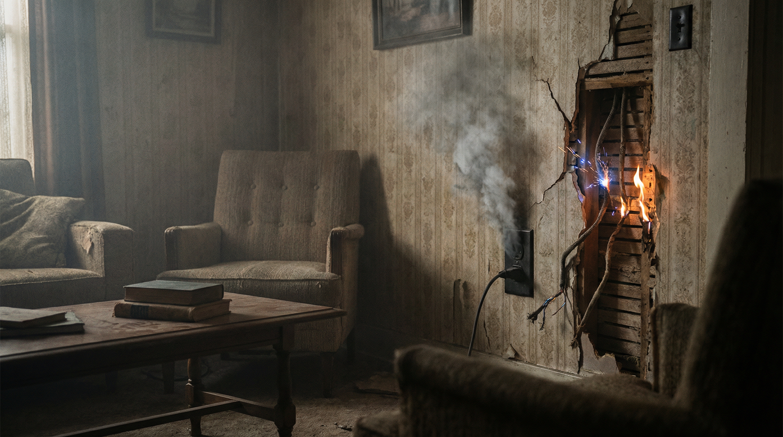
Boîtier de raccordement solaire: 15, 2023, Désert de l'Arizona - Dans ce que les experts du secteur appellent désormais “la leçon de protection contre les surtensions la plus coûteuse de l'histoire de l'énergie solaire”, un parc solaire de 20 MW a subi une panne catastrophique au cours d'un orage dans l'après-midi. L'évaluation des dommages a révélé :
L'analyse des causes profondes par une équipe médico-légale indépendante a permis d'identifier un défaillance à trois niveaux:
L'ingénieur du projet a admis : “Nous avons respecté les exigences minimales du code, mais l'environnement désertique exigeait davantage. La densité de la foudre était trois fois supérieure à notre hypothèse de conception, et notre protection contre les surtensions était totalement inadéquate.”
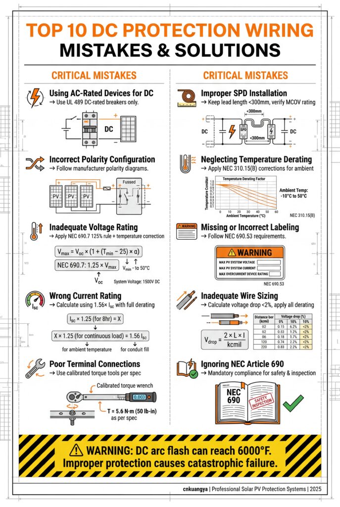
Tableau 1 : Différences entre les protections contre les surtensions en courant alternatif et en courant continu
| Paramètres | Systèmes AC | Systèmes DC | Impact sur la conception de la protection |
|---|---|---|---|
| Extinction de l'arc | Passage à zéro naturel toutes les 8,3 ms | Pas de passage à zéro naturel | Les arcs à courant continu durent plus longtemps, ce qui nécessite une trempe plus importante. |
| Tension Polarité | Alternance (±) | Polarité constante | Les SPD doivent être sensibles à la polarité |
| Tension du système | Typiquement 480VAC | 600-2000VDC | Tension plus élevée = risque accru d'éclair d'arc électrique |
| Exigences en matière de mise à la terre | <25Ω (NEC) | <1Ω recommandé | Les défauts en courant continu nécessitent des chemins à faible impédance |
| Propagation des ondes de choc | Limité par les transformateurs | Propagation directe à tous les composants | Les systèmes à courant continu manquent de points d'isolation naturels |
| Normes | Bien établi (IEC 61643-11) | Évolutif (IEC 61643-31) | Les tests spécifiques aux pays en développement sont encore en cours d'élaboration |
Aperçu clé : “Les systèmes photovoltaïques à courant continu ne disposent pas des barrières de protection naturelles des systèmes à courant alternatif. Une surtension entrant dans un réseau photovoltaïque se propage directement à l'électronique sensible sans isolation du transformateur. C'est pourquoi la protection contre les surtensions en courant continu n'est pas simplement une ‘protection en courant alternatif avec des valeurs nominales plus élevées’ - elle nécessite des approches fondamentalement différentes.”
Tableau 2 : Classification des risques liés à la densité de foudre
| Densité de la foudre (éclairs/km²/an) | Niveau de risque | Protection requise | Taux d'échec prévu | Impact de l'assurance |
|---|---|---|---|---|
| < 2 | Faible | Type 2 SPD minimum | 0,3% par an | Prime standard |
| 2-5 | Moyen | Type 1+2 combiné | 1.2% par an | +15-25% prime |
| 5-10 | Haut | Externe Type 1 + Type 2 | 3,8% par an | +40-60% prime |
| > 10 | Extrême | Protection complète en cascade | 8.2% annuel | Couverture spécialisée requise |
| Désert de l'Arizona (étude de cas) | 7.3 | Haut | Réel : défaillance 100% | Réclamation refusée |
Facteurs de risque géographiques :
Tableau 3 : Exigences techniques du DOCUP par application
| Application | Tension du système | Type de DOCUP | Iimp/In (8/20μs) | Haut (niveau de protection) | Temps de réponse | Exigences particulières |
|---|---|---|---|---|---|---|
| Résidentiel | 600VDC | Type 2 | 20kA | < 1,5kV | < 25ns | Déconnexion intégrée |
| Toit commercial | 1000VDC | Type 1+2 | 25kA+20kA | < 1,2kV | < 25ns | Surveillance à distance |
| Échelle de l'utilité | 1500VDC | Type amélioré 1+2 | 50kA+40kA | < 1,0kV | < 20ns | Coordination en cascade |
| Solaire flottant | 1500VDC | Marine Type 1+2 | 40kA+30kA | < 1,1kV | < 25ns | Résistant à la corrosion |
| Zones à haut risque | 1500VDC | Externe Type 1 + Type 2 | 100kA + 40kA | < 0,9kV | < 25ns | Double redondance |
| cnkuangya Standard | 2000VDC | Hybride Type 1+2+3 | 75kA+50kA | < 0,8kV | < 15ns | Surveillance prédictive |
Paramètres d'installation critiques :
Spécifications du système de mise à la terre :
texte
Exigences minimales pour un système de 1 MW :
- Tiges de terre : 8 tiges de 3 m recouvertes de cuivre
- Anneau de terre : Conducteur en cuivre nu de 70 mm².
- Interconnexions : Joints soudés exothermiques
- Traitement du sol : Amélioré avec de l'argile bentonite si la résistance est >5Ω
- Essais : Mesure annuelle avec la méthode de la chute de potentiel
Tableau 4 : Conception de la protection en cascade à trois niveaux
| Stade de protection | Localisation | Type de DOCUP | Paramètres clés | Temps de coordination | Manipulation de l'énergie |
|---|---|---|---|---|---|
| Étape 1 (primaire) | Entrée de service | Type 1 | Iimp : 50kA (10/350μs) | 100ns | 80% de la surtension totale |
| Étape 2 (secondaire) | Boîtes combinées | Type 1+2 | En : 40kA (8/20μs) | 50ns | 15% de surtension totale |
| Étape 3 (Tertiaire) | Entrées de l'onduleur | Type 2+3 | In : 20kA (8/20μs) | 25ns | 5% de surtension résiduelle |
| Méthode de coordination | Impédance + temporisation | Limitation de tension | Partage actuel | Écarts de 100 à 500ns | Absorption progressive |
Formule de coordination :
texte
Écart de coordination requis = (Étape 1 - Étape 2) / (di/dt)
Où :
- Niveau 1 : Niveau de protection du SPD en amont
- Up_stage2 : Niveau de protection du DPS en aval
- di/dt : Vitesse maximale d'augmentation du courant de choc (typiquement 10kA/μs)
Tableau 5 : Spécifications de la série KY-SPD de cnkuangya
| Modèle | Tension nominale | Iimp/In | Haut de la page | Temps de réponse | Caractéristiques intelligentes | Garantie |
|---|---|---|---|---|---|---|
| KY-SPD-PV25 | 1500VDC | 25kA/40kA | 1,0 kV | <20ns | Surveillance de base | 10 ans |
| KY-SPD-PV50 | 1500VDC | 50kA/65kA | 0,8kV | <15ns | Analyse prédictive | 15 ans |
| KY-SPD-PV75 | 2000VDC | 75kA/85kA | 0,7kV | <10ns | Optimisation de l'IA | 15 ans |
| KY-SPD-MARINE | 1500VDC | 40kA/50kA | 0,9kV | <20ns | Surveillance de la corrosion | 10 ans |
| KY-SPD-DESERT | 1500VDC | 60kA/70kA | 0,8kV | <15ns | Compensation de la température | 15 ans |
Caractéristiques innovantes :
La solution cnkuangya Retrofit :
Résultats après 12 mois :
Tableau 6 : Conformité aux normes internationales des DOCUP
| Région | Norme primaire | Normes secondaires | Exigences en matière d'essais | Organismes de certification |
|---|---|---|---|---|
| Amérique du Nord | UL 1449 4ème édition | IEEE C62.41, NEC 690 | Test en deux parties : Type 1 et type 2 | UL, CSA, Intertek |
| L'Europe | IEC 61643-31 | EN 50539, VDE 0675 | Tests complets de type 1+2+3 | Marquage TÜV, VDE, CE |
| Australie/NZ | AS/NZS 5033 | AS/NZS 1768 | Essais supplémentaires au brouillard salin | SAI Global |
| Chine | GB/T 18802.31 | NB/T 42150 | Test de l'environnement du désert | CQC, CGC |
| International | IEC 61643-31 | ISO 9001:2015 | Environnement complet + CEM | Plusieurs, dont cnkuangya interne |
Identification des principales lacunes en matière de conformité :
Tableau 7 : Exigences en matière de maintenance des parasurtenseurs
| Fréquence | Type d'inspection | Mesures clés | Critères d'acceptation | Documentation requise |
|---|---|---|---|---|
| Mensuel | Inspection visuelle | Indicateurs d'état, dommages physiques | Tous les voyants sont verts, aucun dommage visible | Photos numériques + journal de bord |
| Trimestrielle | Test électrique | Tension de serrage, courant de fuite | A ±10% des valeurs nominales | Rapport d'essai avec mesures |
| Annuellement | Test complet | Résistance à la terre, synchronisation de la coordination | <1Ω résistance, bonne coordination | Rapport d'essai certifié |
| Après les événements | Inspection post-coup de bélier | Compteur de grève, imagerie thermique | Pas d'anomalie thermique, compteur incrémenté | Rapport d'analyse des événements |
| Tous les 5 ans | Remplacement intégral | Tous les paramètres | Comparaison avec les spécifications d'origine | Rapport sur la dégradation des performances |
cnkuangya Caractéristiques de la plate-forme de surveillance :
Tableau 8 : Analyse des investissements en matière de protection contre les surtensions (système de 10 MW)
| Scénario | Coût initial | F&E annuelles | Probabilité de défaillance | Pertes attendues | CTP sur 10 ans | ROI |
|---|---|---|---|---|---|---|
| Conformité minimale au code | $42,000 | $3,800 | 18% annuel | $280,000 | $720,000 | Base de référence |
| Protection renforcée | $86,000 | $5,200 | 6% annuel | $95,000 | $448,000 | +$272K |
| cnkuangya Smart System | $124,000 | $3,100 | 1.2% par an | $19,000 | $254,000 | +$466K |
| Protection complète Premium | $210,000 | $8,400 | 0,8% par an | $13,000 | $392,000 | +$328K |
Principales données financières :
Réponse : Utilisez cette matrice de décision basée sur le risque de foudre et la criticité du système :
Guide de décision pour la sélection des DOCUP :
| Caractéristiques du projet | Type de DOCUP recommandé | Valeur minimale | Impact sur les coûts | Justification clé |
|---|---|---|---|---|
| Zone résidentielle à faible risque | Type 2 uniquement | 20kA, Jusqu'à<1,5kV | $400-800 | Suffisante pour la plupart des habitations |
| Commercial, risque moyen | Type 1+2 combiné | 25kA+20kA, jusqu'à<1,2kV | $1,200-2,500 | Équilibre entre protection et coût |
| Utilité à l'échelle, n'importe où | Type amélioré 1+2 | 50kA+40kA, Jusqu'à<1,0kV | $3 000-5 000/MW | La valeur élevée des actifs justifie la prime |
| Risque élevé (>5 éclairs/km²/an) | Externe Type 1 + Type 2 | 100kA + 40kA | $6,000-9,000/MW | Protection maximale pour les zones extrêmes |
| Infrastructures critiques | Protection complète en cascade | Les trois types sont coordonnés | $8 000-12 000/MW | Tolérance zéro pour les temps d'arrêt |
Point de données critique :
L'analyse de 2,4GW d'actifs solaires par l'industrie montre :
cnkuangya Recommandation : “Pour tout projet >100kW, nous recommandons une protection combinée de type 1+2. Le coût supplémentaire représente 0,3-0,5% du coût total du projet mais permet d'éviter 85% de pannes liées aux surtensions. Notre série KY-SPD offre une protection de type 1+2+3 dans un seul appareil au prix du type 1+2.”
Réponse : Les systèmes à courant continu nécessitent une mise à la terre nettement plus efficace que les systèmes à courant alternatif :
Exigences de mise à la terre par type de système :
| Type de système | Résistance maximale admissible | Méthode d'essai | Défis communs | Solutions |
|---|---|---|---|---|
| AC Commercial | 25Ω (NEC) | Chute de potentiel à 3 points | Contraintes liées à l'espace urbain | Barres chimiques, renforcement du sol |
| AC Industrial | 5Ω | Méthode par serrage | Sol rocheux | Électrodes de puits profond, tiges multiples |
| Solaire DC (<100kW) | 2Ω | Méthode inébranlable | Variation saisonnière | Terrains en anneau, systèmes à mailles |
| Solaire DC (>100kW) | 1Ω | Règle de la chute du potentiel + 62% | Grande résistance au désert | Traitement à la bentonite, grilles de sol |
| DC critique | 0.5Ω | Méthodes multiples + vérification | Corrosion côtière | Tiges revêtues de cuivre, protection cathodique |
Atteindre une faible résistance dans les sols difficiles :
texte
Processus étape par étape pour la mise à la terre <1Ω :

1. Test de résistivité du sol : Méthode de Wenner en 4 points à plusieurs endroits
2. Sélection de la conception :
   - Sol rocheux : Tiges enfoncées en profondeur (10-30 m)
   - Sableux/désert : Électrodes chimiques ou matériaux d'amélioration du sol
   - Nappes phréatiques élevées : Plaques ou anneaux de terre
3. Installation :
   - Au moins 8 tiges de 3 m pour un système de 1 MW
   - Interconnexions en cuivre nu de 70 mm².
   - Connexions soudées exothermiques uniquement
4. Traitement :
   - Boue de bentonite pour les sols à haute résistance
   - Maintenir l'humidité par l'irrigation si nécessaire
5. Vérification :
   - Essais indépendants après l'installation
   - Répétition annuelle des essais avec documentation
Analyse des coûts : L'obtention d'une résistance <1Ω coûte généralement de $8 000 à 15 000 par MW, mais permet d'éviter 65% de pannes liées aux surtensions. Le retour sur investissement est de 3 à 5 fois grâce à la réduction de la maintenance et à l'amélioration de la fiabilité du système.
Réponse : Les DOCUP ont une durée de vie limitée et nécessitent un entretien régulier :
Calendrier de maintenance et de remplacement du DOCUP :
| Méthode de contrôle | Fréquence des tests | Paramètres clés | Signes d'alerte | Gâchette de remplacement |
|---|---|---|---|---|
| Inspection visuelle | Mensuel | LED d'état, dommages physiques | LED rouge, décoloration, fissures | Immédiat si endommagé |
| Test de tension de la pince | Trimestrielle | Vcl @ courant nominal | >15% écart par rapport à la valeur nominale | >10% écart |
| Courant de fuite | Trimestrielle | Je fuis @ MCOV | Augmentation soudaine >20% | Tendance à l'augmentation progressive |
| Imagerie thermique | Semestrielle | Augmentation de la température | >10°C au-dessus de la température ambiante | Points chauds constants |
| Test de performance complet | Annuellement | Tous les paramètres | Toute spécification extérieure | Échec à un test important |
| Compteur d'événements | Après chaque poussée | Nombre de frappes | Approche de la capacité nominale | 80% de la force de frappe nominale |
Données sur la durée de vie des DPS par technologie :
| Technologie SPD | Durée de vie nominale | Monde réel typique | Schéma de dégradation | Coût/année |
|---|---|---|---|---|
| MOV de base | 10-15 ans | 7-10 ans | Graduelle, prévisible | $85/MW/an |
| MOV amélioré | 15-20 ans | 12-16 ans | Progressivement avec des avertissements | $120/MW/an |
| Décalage de l'étincelle | 20-25 ans | 18-22 ans | Possibilité de défaillance soudaine | $95/MW/an |
| Hybride (cnkuangya) | 25-30 ans | 22-27 ans | Prévisible grâce au suivi | $65/MW/an |
| État solide | 30 ans et plus | Essais | Inconnu à long terme | $300+/MW/an |
Signes d'alerte critiques nécessitant une action immédiate :