Zona industrial de WengYang Yueqing Wenzhou 325000
Horas de trabajo
De lunes a viernes: de 7.00 a 19.00 horas
Fin de semana: 10.00 A 17.00 HORAS
Zona industrial de WengYang Yueqing Wenzhou 325000
Horas de trabajo
De lunes a viernes: de 7.00 a 19.00 horas
Fin de semana: 10.00 A 17.00 HORAS

Plan PoE surge protection for outdoor camera networks. Compare power and Ethernet SPDs, verify data and power compatibility, review placement and bonding, and use a practical troubleshooting matrix.
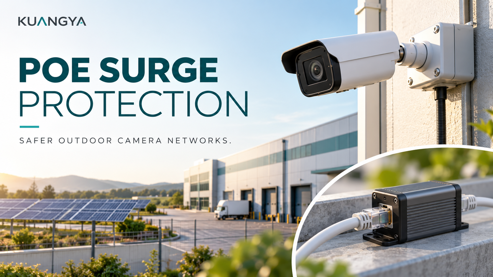
PoE surge protection addresses a risk that a power-panel SPD alone cannot cover: transient overvoltage arriving through the copper Ethernet cable connected to an outdoor camera. A network may have protected AC power and still leave its camera ports exposed through an outdoor data route.
The right solution is not simply an RJ45 box with the largest surge number. It must pass the required Ethernet data and Power over Ethernet supply, suit the environment, and be installed within a coordinated bonding and protection design. This guide follows a practical outdoor-camera project from cable-route review to procurement and maintenance.
It is intended for system integrators, electrical panel builders and project buyers. Installation, grounding and testing should be completed by qualified personnel using the exact equipment instructions and applicable local requirements. No surge protector guarantees survival of every lightning event.
Power over Ethernet combines network communication and electrical power on a compatible copper link. The camera may not have a separate mains lead, but that does not make its incoming connection irrelevant to surge protection. The power-sourcing equipment, cable route and camera form one system that needs a coordinated review.
A useful starting point is to draw every conductive connection entering the equipment. Include the AC supply to the switch or injector, the outdoor Ethernet cable and any additional alarm, audio or control connections. Protection of one connection should not be mistaken for protection of all of them.
PoE surge protection therefore complements, rather than replaces, protection on the electrical distribution side. A power SPD and an Ethernet SPD serve different interfaces. Neither should be substituted for the other merely because both are described as surge protective devices.
Imagine a warehouse with an indoor PoE switch, a cable crossing an exterior wall and a camera mounted at a vehicle entrance. The switch is supplied from a distribution board that already contains an SPD. The owner asks whether the camera is now adequately protected.
The first response should be a route survey, not a product recommendation. Where does the copper cable run? Is it exposed outside, routed between structures or installed close to other services? Where does it enter the building? What bonding facilities and suitable mounting locations actually exist?
Those answers establish the scope of the PoE surge protection design. They also reveal whether the installer is protecting only the outdoor device, only the indoor network equipment or both. A product name on the quotation cannot answer those location questions.
Axis discusses an arrangement with protection adjacent to a distant outdoor camera and additional protection at the building entry for indoor equipment. Its guidance also emphasizes the grounding and shielding path in its camera systems. See the official Axis white paper on power surges. Apply the relevant equipment instructions rather than treating an example as a universal installation drawing.
| Pregunta | Power-panel SPD | PoE-compatible Ethernet SPD |
|---|---|---|
| Which interface is being considered? | The electrical supply circuit covered by its ratings and connection | The compatible copper network interface |
| What must remain compatible? | Supply voltage, earthing arrangement, protection coordination and installation | Data rate, PoE duty, pair arrangement, signal interface and installation |
| What is not automatically covered? | A separate outdoor Ethernet route | The AC supply feeding a switch or injector |
| How should it be selected? | From the power-system design and exact product documentation | From the network and power requirements of the complete link |
The distinction matters when an outdoor device shares a building with a solar installation. A DC SPD selected for a PV array is not an Ethernet protector. Its voltage and interface requirements are different. Do not adapt a power SPD into an RJ45 circuit using improvised connections.
For the broader standards context, see our guide to IEC 61643 and surge protective devices. This article focuses specifically on PoE surge protection and the network-link decisions that a general power-panel specification can miss.
Matching plugs are only the beginning. Two devices may both have RJ45 sockets while supporting different network speeds, power arrangements or environments. Before approving a protector, compare its complete data sheet with the switch, injector and powered-device requirements.
The PoE surge protection review should identify the applicable PoE standard or proprietary powering scheme. Confirm the supported power level and pair arrangement for the exact device. Do not assume that a generic statement such as PoE compatible covers every higher-power camera or access point.
A fixed camera and a camera with motors, infrared illumination or heaters can have different power demands. Base the review on the manufacturer’s declared maximum operating requirements, including enabled accessories, rather than a convenient reading taken under one daytime condition.
Also distinguish available power at the source from the power required at the device. Cable and connection losses belong in the system budget. A surge protector does not create additional PoE capacity, and installing one does not correct an undersized source or unsuitable cable.
| Specification to record | Por qué es importante | Evidence to request |
|---|---|---|
| Ethernet data rate | The protector must support the intended network link | Documented supported speed for the exact model |
| PoE compatibility | The power arrangement must match the source and powered device | Supported standards, modes, power and current limits |
| Protected conductors and modes | A connector shape does not describe the protection circuit | Manufacturer interface and protection specifications |
| Surge performance | Values only make sense with their test conditions | Waveform, protection mode and relevant test information |
| Medio ambiente | An indoor unit may need a suitable enclosure | Temperature, moisture and installation requirements |
| Bonding and shielding | The installed protection path must follow the design | Grounding terminal and cable-shield instructions |
A large surge-current value does not demonstrate adequate network performance. Conversely, successful gigabit negotiation does not establish surge performance. PoE surge protection has to satisfy both the communication requirement and the protective requirement.
Compare like-for-like data. A surge-current number without its waveform and protection mode is incomplete. A headline maximum should not be treated as a universal measure of service life or proof that one device is suitable for every site.
As an example of the information a detailed data sheet can provide, TRENDnet lists network speed, PoE support, environmental ratings and protection modes separately for its TI-OS300. Its stated capabilities apply to that model, not all Ethernet SPDs. See the official TI-OS300 product specifications.
For procurement, place these fields in separate columns. That makes it easier to reject an otherwise attractive quotation that omits one essential capability. It also prevents a supplier from answering a network-speed question with a surge-current number.
The location should follow the exposure and the equipment being protected. Identify building entries, exposed route sections, remote equipment and the available bonding arrangement. Then apply the manufacturer’s installation requirements within the project’s overall protection design.
A cabinet may be a convenient location, but convenience alone is not enough. Consider whether unprotected and protected cable sections are routed sensibly and whether the unit can be inspected without disturbing unrelated circuits. The design should identify the device ports and any directional labels.
PoE surge protection at a remote camera also needs an environmental plan. If the unit is not rated for direct exposure, specify an appropriate enclosure. Include connectors, glands, cable entry and access for service; the protector housing is only one part of the installed assembly.
Do not turn this into a universal distance rule. Two installations with similar cable lengths may have different routes, grounding arrangements and equipment. A project-specific layout is more reliable than copying a photograph and estimating where to mount the box.
Follow the exact protector and equipment instructions for bonding and cable shielding. Do not leave a required ground connection unused simply because the camera image appears normal. Normal operation and surge performance are different questions.
Likewise, a cable marked shielded is not the complete answer. The installer must review the connectors, couplings and equipment interfaces specified in the design. A purchasing list that only names a cable category may omit important installation details.
PoE surge protection should be integrated with the site’s bonding system by qualified personnel. Do not improvise an isolated ground rod or attach the protector to a convenient metal object without evaluating the electrical design. The objective is not merely to find somewhere to fasten a green wire.
Document the intended bonding point and connection requirements on the installation drawing. If that point cannot be reached as designed, resolve the change before commissioning. Our article on SPDs and grounding explains why a ground connection must be considered as part of the protection arrangement.
For a link between separate buildings, compare copper with a properly designed fiber connection early in the project. An all-dielectric optical link does not provide the same conductive data path as copper Ethernet. However, the remote equipment still needs power, and metallic cable elements or other connected services require their own assessment.
Fiber is therefore a design alternative, not a claim that the entire remote installation is now immune to surges. Evaluate the local power supply, network equipment, environmental requirements and maintenance capability alongside the data connection.
PoE surge protection remains relevant wherever exposed copper PoE segments remain. A fiber uplink to a remote switch does not automatically protect the copper connections from that switch to cameras. Mark those segments individually on the network drawing.
This comparison can be made before purchasing hardware. Ask the designer to show which conductive paths disappear, which remain and how the remote devices receive power. That gives the buyer a clearer basis for comparing total installed cost and service requirements.
Return to the hypothetical warehouse camera. The project team initially specifies an Ethernet surge protector only because a previous site used one. No one has recorded the camera’s maximum power requirement or the expected network speed.
The revised review starts with the actual equipment references. The integrator records the switch port capability, camera power requirement, cable route and intended operating features. The electrical designer reviews exposure and bonding, while the buyer requests matching product documentation.
The PoE surge protection specification then identifies the required interface, operating environment and installation locations. It does not name an arbitrary surge rating as the whole requirement. Any uncertainty about compatibility remains an open issue until the manufacturer or designer resolves it.
Before handover, the installer verifies normal network and camera operation under the planned operating modes using an approved test procedure. The team records the installed protector model and mounting location so maintenance staff can find it later. No one creates an artificial surge or deliberately faults the circuit to prove that protection works.
This is a planning example, not a universal wiring diagram. Its value is the sequence of decisions: understand the link, define the interfaces, resolve installation requirements, and retain a record of what was approved.
If a problem appears after adding PoE surge protection, do not immediately assume that the SPD has failed or remove it permanently. Compare the symptom with the approved equipment requirements and use a safe, controlled troubleshooting procedure.
| Observed symptom | Checks to include | Do not conclude automatically |
|---|---|---|
| No Ethernet link | Port identification, cable termination, connector seating and supported data rate | That every surge protector blocks network traffic |
| Camera starts but restarts later | Power budget, cable losses and enabled camera features | That the surge-current rating is too small |
| Link negotiates below the intended speed | Cabling quality and documented capability of every inline component | That a matching RJ45 connector guarantees the intended speed |
| Problems occur after wet weather | Enclosure condition, glands, connectors and signs of moisture | That all storm-related failures are electrical surges |
| Several ports fail after an event | All possible incoming paths and the wider installation | That replacing one protector resolves the root cause |
A continuity check or a normal video stream is not certification of PoE surge protection performance. Keep functional testing separate from any specialist protective-device assessment. Follow the manufacturer procedure and replace damaged components only with approved equivalents.
A good request for quotation describes the system rather than asking only for an Ethernet SPD price. Include the powered-device and source references, required data rate, powering scheme, maximum demand, cable route and environmental conditions.
Ask the supplier to identify the exact offered model and provide its data sheet and installation instructions. Request explicit confirmation of the relevant PoE compatibility and any restrictions on mounting, grounding, cable types or port orientation. General marketing language is not a substitute for those documents.
For KUANGYA project inquiries, distinguish the power-panel SPD requirement from the data-line requirement. Ask for confirmation of product availability and application suitability; this educational guide does not claim that every illustrated device is a KUANGYA product or that one model suits every network.
Keep an asset register showing the protector location, ordering reference, commissioning date and linked equipment. Record significant events and maintenance findings. This is more useful than relying on a sticker that simply says lightning protection installed.
Inspection should follow manufacturer guidance and site procedures. Include physical condition, environmental sealing, readable identification and required connections. Do not open equipment or disturb bonding while it is energized merely to perform a quick check.
If PoE surge protection is replaced, review equivalence before fitting a different model. A replacement must satisfy the data and power requirements as well as the protection and environmental requirements. Reuse of the same connector type is not enough.
Also update the record when cameras, switches or injectors change. An upgrade to a higher-power device or faster link can invalidate an earlier compatibility assumption even though the outdoor cable route remains unchanged.
No automatic conclusion follows from having a UPS. Its presence does not establish protection for a separate outdoor copper data route. Review the UPS specifications, power-side design and network-side exposure as separate parts of the system.
No. Select a device explicitly compatible with the intended powering arrangement and equipment. Confirm its documented limits instead of assuming that Ethernet support means support for every PoE application.
A correctly selected device should support its stated data rate when installed within the specified system conditions. Poor cabling, incompatible equipment or an unsuitable inline device can affect operation. Verify the complete channel, not just the advertised protector speed.
That depends on the exposure, equipment and approved design. Consider the remote device and the building entry rather than applying a universal yes or no. Follow the equipment manufacturer’s layout guidance and the site’s bonding requirements.
No. An SPD has defined limits and forms only part of a wider protection approach. Do not use it to justify unsafe exposure or to replace an appropriate lightning-protection assessment.
Not when the manufacturer requires that connection. A functioning network does not prove that the protective path is correctly installed. Have qualified personnel resolve grounding and bonding requirements before relying on the installation.
Effective PoE surge protection begins with a route and interface review. Match the protector to the network speed and power requirements, identify the equipment and cable entries being protected, and document the environmental and bonding requirements.
The result should be a coordinated design rather than an isolated accessory. Keep power-panel protection, Ethernet protection and normal network testing distinct, then bring them together in one verified installation and maintenance record.

