Zona industrial de WengYang Yueqing Wenzhou 325000
Horas de trabajo
De lunes a viernes: de 7.00 a 19.00 horas
Fin de semana: 10.00 A 17.00 HORAS
Zona industrial de WengYang Yueqing Wenzhou 325000
Horas de trabajo
De lunes a viernes: de 7.00 a 19.00 horas
Fin de semana: 10.00 A 17.00 HORAS
Son las 2:47 de la madrugada cuando el sistema de seguridad alerta al responsable de la instalación de unas señales térmicas inusuales en la caja del combinador solar #3. Corre a la instalación de la azotea y descubre lo que todo profesional de la energía solar teme: un arco de CC sostenido, que brilla a más de 3.000 °C (5.400 °F) y consume lentamente los terminales de cobre del interior. El arco ha estado ardiendo durante horas, de forma silenciosa e invisible, alimentado por la incesante energía de un conjunto fotovoltaico de 1.000 voltios. Unos minutos más y la membrana seca del tejado habría ardido.
La investigación revela un error crítico: el dispositivo de protección contra sobrecorriente equivocado. Aunque el componente estaba etiquetado como “disyuntor”, carecía de los mecanismos especializados de extinción de arcos necesarios para las aplicaciones de CC de alta tensión. A diferencia de los sistemas de CA, en los que la corriente pasa naturalmente por cero 120 veces por segundo, la CC mantiene una tensión constante, lo que proporciona a los arcos una energía ilimitada para mantenerse y convertir pequeños fallos en averías catastróficas.
Como ingeniero superior de aplicaciones con más de 15 años de experiencia en el diseño de sistemas de protección solar, he sido testigo de esta situación demasiadas veces. La elección entre fusibles de CC y disyuntores de CC no sólo tiene que ver con el coste inicial o la comodidad, sino que es una decisión que afecta a la seguridad del sistema, la fiabilidad operativa y la economía total del ciclo de vida a lo largo de los 25 años de vida útil de la instalación. No se trata de una comparación superficial de pros y contras. Se trata de un análisis a nivel de ingeniería que le ayudará a seleccionar el dispositivo de protección contra sobrecorriente (OCPD) adecuado para su aplicación fotovoltaica específica, respaldado por datos técnicos, requisitos de códigos y métricas de rendimiento del mundo real.
Antes de comparar soluciones, debemos comprender la amenaza única que hace que la protección de CC sea tan crítica. La física fundamental de la corriente continua crea un riesgo de incendio que simplemente no existe en los sistemas eléctricos de corriente alterna estándar.
En un sistema de CA que funciona a 60 Hz, la tensión y la corriente oscilan de un lado a otro, pasando por cero voltios 120 veces por segundo. Cada paso por cero es una oportunidad natural para que se extinga un arco eléctrico. Piense en ello como la llama de una vela en una brisa rítmica: la llama disminuye repetidamente y debe restablecerse 120 veces por segundo. Al final, si las condiciones no son perfectas, la llama se apaga.
DC es fundamentalmente diferente. Se trata de un flujo constante e incesante de energía en una dirección, como un río que nunca mengua. Una vez que se forma un arco entre los conductores (por una conexión floja, un aislamiento dañado o la entrada de humedad), no hay paso por cero que ayude a extinguirlo. El arco se convierte en un puente de plasma autosostenido, un “soplete” que puede mantener temperaturas superiores a los 3.000 °C, fundiendo fácilmente cobre, aluminio y acero e incendiando cualquier material combustible cercano.
Los paneles solares modernos funcionan con tensiones de CC cada vez más altas: 600 V en sistemas residenciales, 1.000 V en instalaciones comerciales y hasta 1.500 V en proyectos a gran escala. Una tensión más alta facilita el inicio de los arcos y proporciona más energía para mantenerlos. Un arco de 1000 V de CC tiene un poder destructivo exponencialmente mayor que un arco de 120 V de CA: puede atravesar espacios de aire más grandes, penetrar más profundamente en los recintos y mantenerse a través de aislamientos carbonizados que normalmente no serían conductores.
Por eso puede nunca utilizar un disyuntor o fusible estándar de CA en una aplicación de CC. Los dispositivos de protección de CA carecen de los mecanismos internos de extinción de arcos necesarios para interrumpir de forma segura los circuitos de CC bajo carga. Instalar un dispositivo de CA en un sistema de CC es una infracción del código que crea riesgos inmediatos de incendio y explosión.
gráfico LR
    A[Corriente alterna] -->|Cruce por cero 120x/seg| B[Extinción natural del arco]
    C[Corriente Continua] -->|Voltaje Constante| D[Arco Autosostenido]
    D -->|3000°C Plasma| E[Daño Equipo]
    D -->|Fuente de Ignición| F[Peligro de Incendio]

    estilo D relleno:#ff6b6b
    style E fill:#ff6b6b
    estilo F fill:#ff6b6b
    estilo B fill:#51cf66
Conclusión clave #1: Los arcos de CC son puentes de plasma autosostenidos que no se extinguen de forma natural como los arcos de CA. Pueden arder indefinidamente a temperaturas superiores a 3.000 °C, creando graves riesgos de incendio. Por este motivo, los dispositivos especializados de protección contra sobreintensidades de CC con las tensiones nominales y los mecanismos de interrupción de arco adecuados no son en absoluto negociables para los sistemas fotovoltaicos solares. El uso de dispositivos de corriente alterna en circuitos de corriente continua infringe la norma NEC 110.3(B) y crea riesgos para la seguridad.
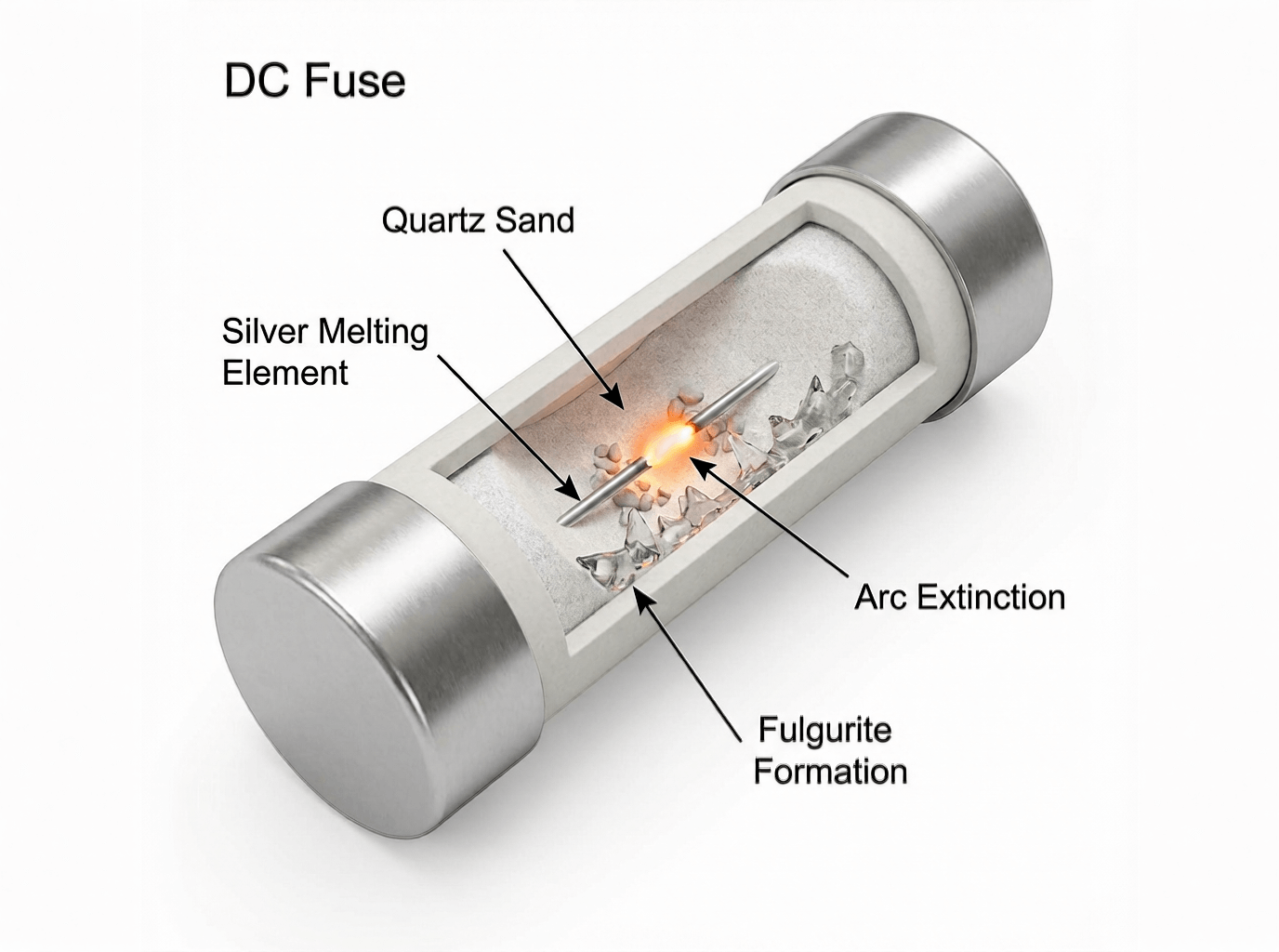
El fusible de CC representa el enfoque más antiguo y fundamental de la protección contra sobrecorriente: un componente diseñado con precisión para autodestruirse y salvar su sistema. Para aplicaciones solares, no utilizamos fusibles genéricos; utilizamos Fusibles con clasificación gPV (según UL 2579 e IEC 60269-6) específicamente formulado para la protección de sistemas fotovoltaicos.
En el corazón de cada fusible hay un elemento metálico -normalmente plata, cobre o una aleación especializada- calibrado con precisión para fundirse a un nivel de corriente específico. El área de la sección transversal del elemento, su longitud y la composición del material determinan sus características de tiempo-corriente.
Cuando la corriente supera el valor nominal del fusible, se produce un calentamiento resistivo. Para sobrecargas menores (125-150% de capacidad nominal), el elemento se calienta gradualmente durante segundos o minutos hasta fundirse. Para cortocircuitos graves (500-1000% de capacidad nominal), el elemento se vaporiza casi instantáneamente -en tan sólo 0,004 segundos- entrando en lo que se denomina el rango de “limitación de corriente”.
Pero fundir el elemento es sólo la mitad de la historia. Cuando el elemento se vaporiza, crea un peligroso arco de CC a través del hueco. Aquí es donde la construcción especializada de fusibles de CC se vuelve crítica:
1. Tensión nominal (VCC): Debe ser igual o superior a la tensión máxima en circuito abierto (Voc) del sistema ajustada a la temperatura más fría prevista. Para una cadena que produzca 460 V en condiciones de prueba estándar, la Voc en tiempo frío podría alcanzar los 525 V, lo que requeriría un fusible de 600 V.
2. Corriente nominal (amperios): NEC 690.8 requiere un dimensionamiento a 156% de la corriente de cortocircuito del circuito (Isc). Para un módulo con una Isc nominal de 9,8 A: 9,8 A × 1,56 = 15,3 A mínimo, por lo que deberá seleccionar un fusible de 20 A (el siguiente tamaño estándar superior).
3. Capacidad de interrupción (AIC): Se trata de la máxima corriente de fallo que el fusible puede despejar con seguridad sin explotar. Los fusibles solares suelen ofrecer potencias nominales de 20 kA, 50 kA o incluso 100 kA, muy superiores a las que pueden alcanzar la mayoría de los disyuntores a un coste comparable.
Capacidad de interrupción ultraalta: Un fusible gPV de 20A y 50.000 AIC cuesta $15-25. Un disyuntor de CC con un AIC equivalente costaría $200-400. Para aplicaciones de alta corriente de defecto (cerca de bancos de baterías o en grandes cajas combinadoras), los fusibles proporcionan una protección superior de forma más económica.
Tiempo de respuesta más rápido: Los fusibles limitadores de corriente actúan en 4 milisegundos o menos durante los cortocircuitos, limitando drásticamente la energía de paso (I²t). De este modo, se protegen los costosos equipos posteriores, como inversores y reguladores de carga, frente al estrés térmico y mecánico.
Simplicidad inherente: Al no tener piezas móviles, los fusibles no pueden fallar mecánicamente. Fallan en un estado “abierto” (seguro) predecible. No hay desviación de calibración, ni lubricación que se seque, ni contactos que se suelden.
Menor coste inicial: El fusible más el soporte suelen costar 20-40% menos que un disyuntor de CC equivalente, lo que los hace atractivos para grandes proyectos con cientos de cadenas.
Funcionamiento de un solo uso: Una vez fundido, el fusible debe sustituirse por completo. Esto requiere mantener un inventario de repuestos e implica un tiempo de inactividad del sistema mientras un técnico accede a la caja del combinador e instala un fusible nuevo.
Riesgo de error humano: Nada impide que alguien sustituya un fusible de 15 A por otro de 30 A, una situación peligrosa que socava toda la protección. La formación y un etiquetado claro son esenciales.
Sin función de conmutación: Un fusible proporciona protección, pero no puede servir como interruptor de desconexión manual. Para el aislamiento de mantenimiento, se necesita un dispositivo de desconexión independiente, lo que añade coste y espacio al armario.
Solución de problemas: En una caja combinadora con doce fusibles, un solo fusible fundido requiere una inspección visual o una prueba de continuidad para identificar qué ramal ha fallado.
Conclusión clave #2: Los fusibles de CC ofrecen la protección de sobreintensidad más robusta y rápida disponible, con capacidades de interrupción de hasta 100 kA a un coste notablemente bajo. Su naturaleza sacrificable y de un solo uso los hace ideales para aplicaciones que priorizan la máxima seguridad y el manejo de corrientes de fallo. Sin embargo, cada evento de fallo requiere una sustitución manual, lo que introduce un tiempo de inactividad operativa y la posibilidad de una sustitución incorrecta, por lo que son más adecuados para sistemas con baja frecuencia de fallos y acceso de mantenimiento profesional.
Si un fusible de CC es un soldado sacrificado en una misión unidireccional, un disyuntor de CC es un guardia altamente entrenado que puede detener una amenaza y volver inmediatamente al servicio. Un disyuntor combina la protección contra sobrecorriente con la capacidad de conmutación manual y, lo que es más importante, puede restablecerse después de dispararse sin necesidad de sustituir ningún componente.
Los disyuntores de CC diseñados para aplicaciones solares (clasificados según UL 489 para unidades más grandes o UL 1077 para protectores suplementarios) utilizan un sofisticado enfoque de doble mecanismo:
Disparo térmico por sobrecargas: En serie con el circuito se coloca una banda bimetálica formada por dos metales con diferentes índices de dilatación térmica unidos entre sí. En caso de sobrecorriente sostenida (125-200% de potencia nominal), la tira se calienta y se dobla proporcionalmente al nivel de corriente. Cuando se dobla lo suficiente, libera un pestillo accionado por resorte y los contactos se abren de golpe. De este modo se gestionan las sobrecargas de “combustión lenta”, como una cadena que transporta 18 A continuos cuando su capacidad nominal es de 15 A.
Disparo magnético por cortocircuito: Una bobina de solenoide que rodea la trayectoria de la corriente genera un campo magnético proporcional al flujo de corriente. Cuando se produce un cortocircuito grave (normalmente de 5 a 20 veces la intensidad nominal), el campo magnético es lo suficientemente intenso como para accionar instantáneamente un émbolo que dispara mecánicamente el interruptor. Esto proporciona una protección casi instantánea (0,02-0,05 segundos) para condiciones de fallo peligrosas.
Este diseño de doble mecanismo crea la característica curva tiempo-corriente de “dos zonas” que define el comportamiento del disyuntor: una respuesta térmica gradual a las sobrecargas y una respuesta magnética instantánea a los cortocircuitos.
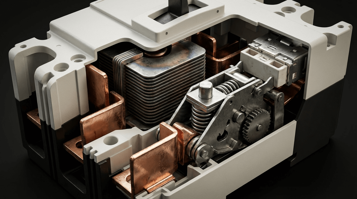
El verdadero reto de ingeniería en un interruptor de CC es extinguir el arco que se forma cuando los contactos se separan bajo carga. Esto se consigue mediante arco vertedor-una sofisticada cámara que contiene una serie de placas metálicas paralelas.
Cuando el interruptor se dispara, los contactos se separan, creando un arco. Las bobinas magnéticas de “soplado” empujan inmediatamente este arco hacia arriba, al conducto de arco. Las placas metálicas dividen el arco grande en múltiples arcos en serie más pequeños y fríos. Estos arcos en serie tienen una mayor caída de tensión total, que se opone a la tensión del sistema, dificultando el paso de la corriente. Al mismo tiempo, las placas absorben calor, enfriando los arcos hasta que ya no pueden sostenerse y se extinguen.
Esta es la razón por la que los disyuntores de CC son más grandes y más caros que los disyuntores de CA equivalentes: el conducto de arco debe ser significativamente más robusto para manejar la energía de arco sostenida de la CC.
Operación reajustable: Tras eliminar una avería, basta con reiniciar el mando para restablecer la alimentación. En el caso de disparos molestos o sobrecargas temporales, esto ahorra horas de inactividad en comparación con la sustitución de fusibles. En instalaciones remotas, esto puede evitar costosas llamadas al servicio técnico.
Diseño de doble función: El disyuntor sirve tanto de protección como de interruptor de desconexión manual. Esto satisface los requisitos NEC 690.13 para un medio de desconexión fotovoltaico, eliminando la necesidad de un dispositivo de desconexión separado.
Rendimiento predecible: Las características de disparo permanecen estables a lo largo de la vida del disyuntor (normalmente 20-30 años). A diferencia de los fusibles, que pueden sustituirse de forma incorrecta, el valor nominal del disyuntor no puede modificarse: está determinado permanentemente por el mecanismo interno.
Coordinación multipolar: Los disyuntores pueden agruparse mecánica o eléctricamente para que un fallo en cualquier polo dispare todos los polos simultáneamente. Esto es fundamental para las cajas combinadoras de varias cadenas en las que se desea un aislamiento completo del circuito.
Capacidad de diagnóstico: Un disyuntor disparado proporciona una indicación visual inmediata del problema. Algunos modelos avanzados incluyen contactos de monitorización remota para integración SCADA.
Mayor inversión inicial: Un disyuntor de CC de calidad cuesta entre 3 y 10 veces más que un fusible y un soporte equivalentes. Por un disyuntor de 400 A a nivel de combinador, hay que pagar entre $500 y 1.500, frente a los $100-200 de una solución basada en fusibles.
Menor capacidad de interrupción: Los disyuntores de caja moldeada (MCCB) estándar suelen ofrecer una capacidad de interrupción de 10-25kA. Para alcanzar capacidades superiores a 50 kA se necesitan modelos especializados muy caros, mientras que los fusibles suelen ofrecer estas capacidades de serie.
Desgaste mecánico: Los interruptores contienen muelles, pestillos y contactos móviles sujetos a fatiga mecánica. Aunque es poco frecuente, los mecanismos pueden atascarse, los contactos pueden soldarse durante eventos de alta corriente y la calibración puede desviarse durante décadas. Los fabricantes recomiendan “ejercitarlos” periódicamente (encenderlos y apagarlos manualmente) para mantener la libertad mecánica.
Tiempo de respuesta más lento: Aunque el disparo magnético es rápido (20-50 ms), sigue siendo entre 5 y 12 veces más lento que la respuesta de 4 ms de un fusible limitador de corriente. Esto permite un mayor paso de energía (I²t), lo que puede someter a tensión a los componentes aguas abajo.
Conclusión clave #3: Los disyuntores de CC proporcionan una flexibilidad operativa excepcional gracias a su naturaleza reajustable y a su funcionalidad de desconexión integrada. Su mecanismo de disparo termomagnético y sus conductos de arco especializados permiten una interrupción segura de la corriente continua, pero esta sofisticación tiene un coste significativamente mayor. Los disyuntores destacan en aplicaciones que requieren un acceso de mantenimiento frecuente, capacidad de operación remota o en las que el tiempo de actividad del sistema es la principal preocupación, siempre que la corriente de fallo de la aplicación no supere la capacidad de interrupción del disyuntor.
Para tomar una decisión de ingeniería con conocimiento de causa, tenemos que comparar estas tecnologías con los parámetros que realmente importan en las instalaciones solares del mundo real: rendimiento de seguridad, impacto económico y características operativas.
| Característica | Fusible CC (gPV) | Disyuntor de CC | Análisis de ingeniería |
|---|---|---|---|
| Método de interrupción del arco | El elemento fundido crea un hueco; la arena de sílice absorbe la energía del arco | La canaleta de arco divide el arco en múltiples arcos en serie, refrigerados por placas metálicas | Ambos son efectivos; la interrupción por fusible es pasiva/química, el disyuntor es activa/mecánica |
| Capacidad de interrupción (AIC) | 20kA-100kA estándar, hasta 200kA disponible | 10kA-25kA estándar, 50kA-100kA para modelos premium | Los fusibles proporcionan un mayor AIC más crítico económicamente cerca de los bancos de baterías donde la corriente de fallo puede superar los 50kA |
| Tiempo de respuesta (fallo alto) | 0,004-0,010 segundos (4-10 ms) en el rango de limitación de corriente | 0,020-0,050 segundos (20-50ms) para disparo magnético | Los fusibles son entre 5 y 12 veces más rápidos y limitan la energía de paso (I²t) para proteger inversores y reguladores de carga sensibles |
| Energía de paso (I²t) | Extremadamente bajo debido a la acción limitadora de corriente | Moderado-permite más energía durante la interrupción | Menor I²t significa menos tensión térmica y mecánica en todos los componentes posteriores |
| Modo de fallo | Siempre falla “abierto” (estado seguro) | Puede fallar “cerrado” si los contactos se sueldan durante un fallo extremo | Los fusibles son intrínsecamente a prueba de fallos; los disyuntores requieren un dimensionamiento adecuado para evitar la soldadura por contacto. |
| Tropiezos molestos | Rare con el dimensionamiento adecuado de gPV y la corrección de temperatura | El disparo térmico puede ser sensible a la temperatura ambiente en cajas de combinadores calientes | Ambos requieren un dimensionamiento adecuado; los disyuntores ofrecen una ligera ventaja con el disparo térmico ajustable en algunos modelos. |
Este análisis supone una instalación comercial típica con ocho cadenas que alimentan una caja combinadora, que experimenta tres eventos de fallo a lo largo de 20 años, con costes de mano de obra de mantenimiento moderados.
| Categoría de costes | Sistema basado en fusibles (8 cadenas) | Sistema basado en disyuntores (8 cadenas) | Delta |
|---|---|---|---|
| Equipamiento inicial | 8× 20A portafusibles: $240 8× fusibles gPV: $160 Fusible principal 100A: $80 Total: $480 | 8× 20A disyuntores de CC: $1.200 Interruptor principal 100A CC: $600 Total: $1.800 | Los disyuntores cuestan $1.320 más por adelantado |
| Mano de obra de instalación | Cableado más sencillo, menos requisitos de par 6 horas @ $85/hr = $510 | Conexiones de terminales más complejas 8 horas @ $85/hr = $680 | Los disyuntores añaden $170 de coste de instalación |
| Inventario de piezas de recambio | 16× fusibles de repuesto (2× cada capacidad) $320 inicial, $0 anual | No necesita consumibles $0 | Los fusibles requieren repuestos $320 |
| Servicio de incidencias de averías (3× en 20 años) | Cada evento: 1 hora de diagnóstico + 1 hora de sustitución + 45 min de desplazamiento $233 por evento × 3 = $699 | Cada evento: 30 min de diagnóstico + 15 min de reinicio + 45 min de desplazamiento $127 por evento × 3 = $381 | Los disyuntores ahorran $318 en llamadas al servicio técnico |
| Coste del tiempo de inactividad (3 eventos) | Promedio de 4 horas por evento @ $150/hora de pérdida de producción $600 por evento × 3 = $1,800 | Media de 1,5 horas por evento @ $150/hr $225 por evento × 3 = $675 | Los disyuntores ahorran $1.125 en tiempos de inactividad |
| Pruebas/mantenimiento (20 años) | Inspección visual anual: $50/año 20 años = $1.000 | Ejercicio anual + inspección: $100/año 20 años = $2.000 | Los disyuntores añaden $1.000 de coste de mantenimiento |
| Sustitución al final de la vida útil | Igual que el equipo inicial $480 | Igual que el equipo inicial $1,800 | Los disyuntores cuestan $1.320 más |
| TOTAL 20 AÑOS | $5,289 | $7,336 | Los fusibles ahorran $2.047 (28% menos TCO) |
Perspectiva crítica: El análisis del coste total de propiedad cambia drásticamente en función de la frecuencia de las averías y los costes del tiempo de inactividad. Para los sistemas con frecuentes disparos molestos o costes de tiempo de inactividad superiores a $500/hora, los disyuntores resultan económicamente favorables a pesar de los mayores costes de los equipos.
| Especificación | Fusible CC (gPV) | Disyuntor de CC | Orientación para la selección |
|---|---|---|---|
| Tensión nominal | 600VDC, 1000VDC, 1500VDC | 600VDC, 1000VDC, 1500VDC | Igual disponibilidad; verificar que el valor nominal es igual o superior a la Voc en tiempo frío × 1,15 |
| Intensidad nominal (nivel de cadena) | 1A-30A en incrementos estándar | 10A-63A (opciones limitadas de baja corriente) | Los fusibles ofrecen un dimensionamiento más granular para cadenas pequeñas; los disyuntores empiezan con un mínimo de 10 A. |
| Temperatura de funcionamiento | -40°C a +85°C (estándar) | De -25°C a +70°C (por encima de 40°C es necesaria una reducción de potencia) | Los fusibles son más adecuados para entornos de calor/frío extremos; el disparo térmico del disyuntor es sensible a la temperatura. |
| Normas de certificación | UL 2579 (fusible gPV), IEC 60269-6 | UL 489 (MCCB), UL 1077 (suplementario), IEC 60947-2 | Compruebe que los valores nominales de tensión Y corriente están certificados para CC; los valores nominales de CA no tienen sentido. |
| Tamaño (20A) | 10mm × 38mm cilíndrico + soporte | Montaje en carril DIN de 18 mm de ancho | Los fusibles 60% son más compactos, lo que es importante en cajas de combinadores abarrotadas. |
| Complejidad de la instalación | Pinza de muelle (sin par de apriete) | Tornillos de los terminales (se requiere un par de apriete específico) | Los fusibles se instalan más rápido pero ofrecen una conexión menos robusta; los disyuntores requieren una llave dinamométrica |
| Mantenimiento de campo | Requiere herramienta de extracción de fusibles, inventario de recambio | Reajuste con manivela; sin herramientas ni repuestos | Los martillos rompedores eliminan la necesidad de un inventario de piezas de repuesto in situ |
El amperaje le indica si un dispositivo protegerá; la curva tiempo-corriente le indica cuando. Comprender estas curvas es esencial para una correcta coordinación y protección selectiva en los sistemas solares.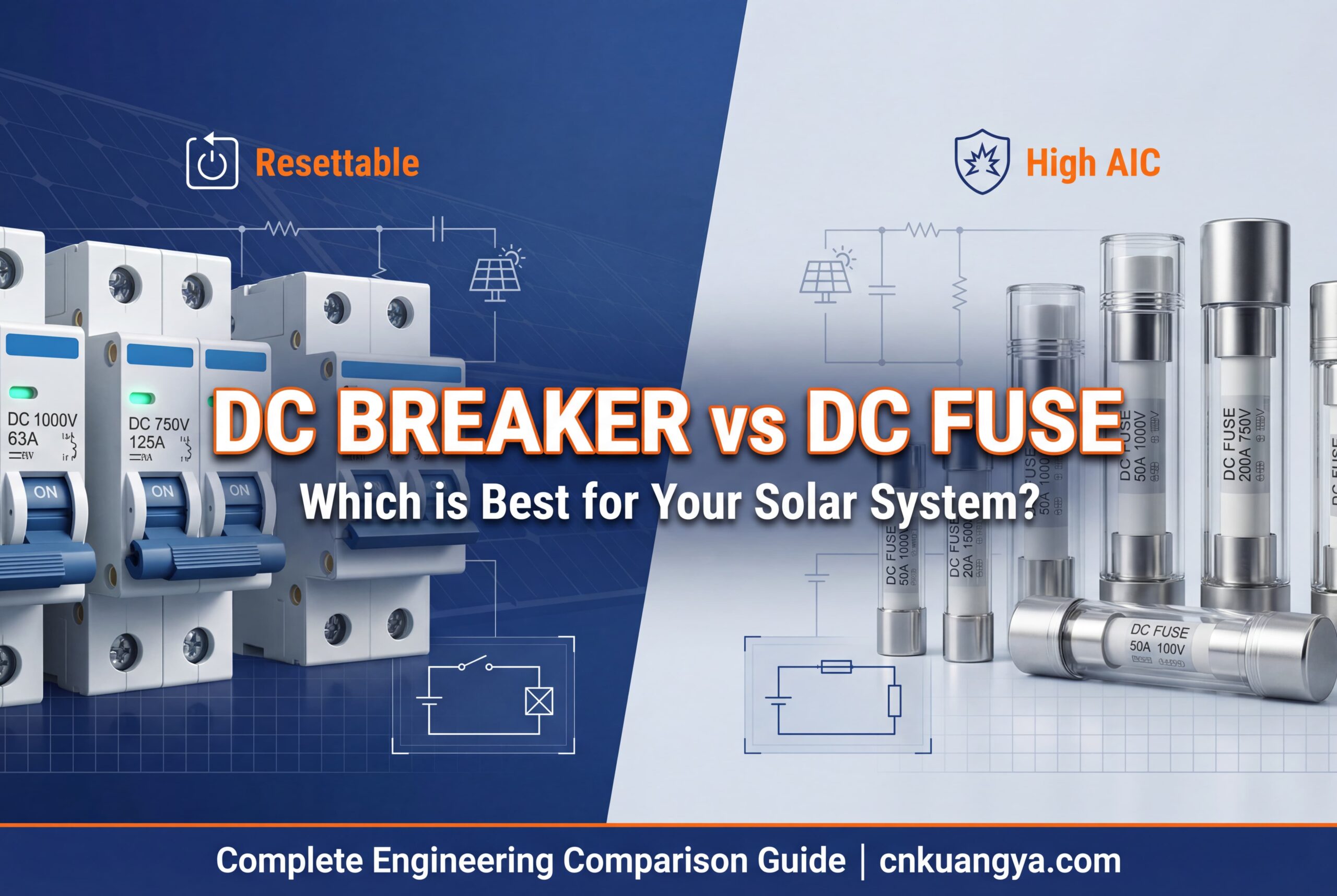
Una curva tiempo-corriente (TCC) representa la corriente de defecto (eje x) en función del tiempo necesario para que se abra el dispositivo de protección (eje y, escala logarítmica). La curva muestra que los dispositivos responden más rápido a corrientes más altas, siguiendo una relación de “tiempo inverso”.
Característica del fusible CC: Una curva simple y suave de tiempo inverso. A bajas sobrecargas (150% de capacidad nominal), el fusible puede tardar más de 600 segundos en fundirse. A altas corrientes de fallo (1000% de capacidad nominal), se funde en 4-10 milisegundos, entrando en su rango de “limitación de corriente”, en el que realmente evita que la corriente de fallo alcance su máximo teórico.
Característica del interruptor de CC: Una curva de dos zonas:
%%{init: {'theme':'base', 'themeVariables': { 'primaryColor':'#f0f0f0'}}}%%
xychart-beta
    title "Curvas Tiempo-Corriente: Respuesta del fusible frente al disyuntor"
    eje x "Corriente (múltiplo de la corriente nominal)" [1, 2, 5, 10, 20, 50, 100]
    eje y "Tiempo hasta disparo (segundos)" [0,01, 0,1, 1, 10, 100, 1000]
    línea "Fusible 20A gPV" [800, 60, 3, 0,15, 0,03, 0,006, 0,004]
    línea "Disyuntor 20A CC" [900, 180, 25, 8, 0,04, 0,04, 0,04]
La energía total suministrada durante un fallo es proporcional a I²t (corriente al cuadrado × tiempo). Un fusible que se despeja en 4 ms a 1000 A proporciona mucha menos energía destructiva que un disyuntor que se despeja en 40 ms a la misma intensidad:
El disyuntor permite 10 veces más energía antes de despejarse. Esta energía adicional genera fuerzas mecánicas (proporcionales a I²), tensión térmica y daños potenciales en los condensadores de entrada del inversor, los contactores de CC y el aislamiento del cableado.
Aplicación de ingeniería: En sistemas con inversores caros o componentes electrónicos sensibles, la menor energía de paso de los fusibles limitadores de corriente proporciona una protección superior de los componentes, lo que puede prolongar la vida útil de los equipos al evitar el estrés acumulado por fallos.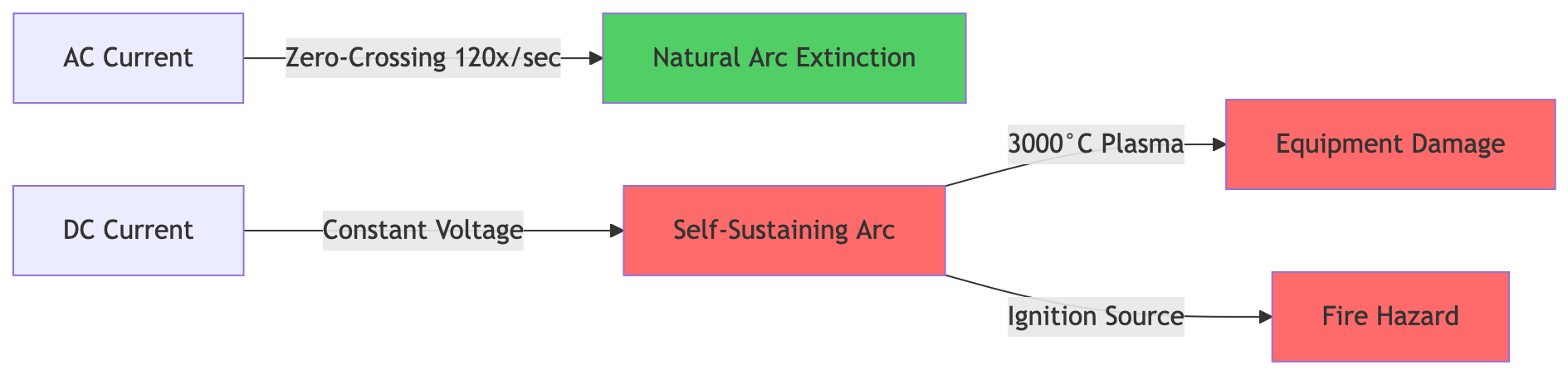
Conclusión clave #4: Las curvas de tiempo-corriente revelan la diferencia fundamental en la filosofía de protección: los fusibles proporcionan una respuesta de tiempo inverso única y de acción rápida que limita drásticamente la energía de fallo, mientras que los disyuntores ofrecen una respuesta sintonizable de dos zonas que tolera las sobrecargas temporales pero responde más lentamente a los cortocircuitos. Para aplicaciones que priorizan la máxima protección de los equipos, las características superiores de I²t de los fusibles ofrecen ventajas cuantificables. Para los sistemas que requieren tolerancia a las corrientes de irrupción o a las sobrecargas temporales, el disparo térmico ajustable de los disyuntores proporciona flexibilidad operativa.
La teoría y las especificaciones son esenciales, pero los proyectos solares requieren decisiones prácticas. Utilice este marco para seleccionar la arquitectura de protección adecuada para su instalación específica.
Tensión máxima del sistema: Determina la tensión en circuito abierto (Voc) de tu cadena más larga a la temperatura más fría prevista:
Corriente máxima del circuito: Calcule la capacidad de corriente continua necesaria:
Corriente de defecto disponible: Esto determina la capacidad de interrupción necesaria (AIC). Para combinadores de cadenas alimentados por 8-12 cadenas:
En el caso de los sistemas de baterías, el cálculo de la corriente de fallo es más complejo: las baterías pueden suministrar entre 10.000 y 50.000 A, dependiendo del tamaño del banco y de la longitud del cable. Esto hace que a menudo se opte por fusibles de alta capacidad (20kA-100kA AIC) debido a consideraciones de coste.
Artículo 690 de NEC Requisitos obligatorios:
Consideraciones sobre la ubicación de la instalación:
| Ubicación | Ventajas de los fusibles | Ventajas del disyuntor | Recomendación |
|---|---|---|---|
| Combinador de cadenas (tejado) | Alto AIC, tamaño compacto, bajo coste | Indicación visual de disparo, sin inventario de sustitución | Fusibles para instalaciones sensibles a los costes Interruptores para facilitar la resolución de problemas |
| Recombinador a nivel del suelo | Tecnología sencilla y probada | Actúa como desconexión necesaria, reiniciable | Interruptores para mayor comodidad operativa |
| Circuito de la batería | AIC extremadamente alto (50kA-100kA) económicamente disponible | Reiniciable para procedimientos de mantenimiento de la batería | Fusibles para la máxima seguridad Interruptores si requisito AIC < 25kA |
| Entrada inversor | Limitación rápida de la energía de paso | Sirve como desconexión obligatoria según NEC 690.13 | Interruptores para cumplir la normativa y proteger el inversor |
Accesibilidad del sitio:
Tolerancia al tiempo de inactividad:
Capacidades de mantenimiento:
Necesidades de resolución de problemas:
Utilice el marco del análisis económico de la sección 4, ajustado a sus parámetros específicos:
Cuando los fusibles ganan económicamente:
Cuando los rompedores ganan económicamente:
Ejemplo de análisis de equilibrio: Para un sistema de 8 cables con dos fallos previstos en 20 años y unos costes por tiempo de inactividad de $200/hora, los fusibles ofrecen un TCO inferior en aproximadamente $1500. Si los costes por tiempo de inactividad superan los $600/hora, los interruptores resultan más rentables.
Elija fusibles de CC cuando:
Elija interruptores automáticos de CC cuando:
Considerar un enfoque híbrido:
Los sistemas con un diseño óptimo utilizan ambos tecnologías estratégicamente:
Esta arquitectura híbrida proporciona simultáneamente cumplimiento normativo, comodidad operativa y optimización de costes.
Configuración típica: 8-16 cadenas de paneles de 300-400 W que alimentan un inversor de cadena
Protección recomendada:
Consideraciones especiales: NEC 690.11 requiere protección contra fallos de arco para los sistemas montados en tejados. Normalmente está integrada en el inversor, pero verifique la compatibilidad con su configuración de fusibles/interruptores.
Configuración típica: Cajas combinadoras múltiples (8-12 cadenas cada una) que alimentan el recombinador central y el inversor
Protección recomendada:
Consideraciones especiales: El análisis del riesgo de arco eléctrico según NFPA 70E es necesario para la seguridad de los trabajadores. Los fusibles limitadores de corriente pueden reducir significativamente la energía incidente del arco eléctrico y los requisitos de EPI.
Requisito crítico: Los bancos de baterías pueden generar más de 10.000 A en cortocircuitos. Esto exige una capacidad de interrupción excepcional.
Protección recomendada:
Nota Crítica de Seguridad: La protección del circuito de la batería es vital. Calcule siempre la corriente de cortocircuito teniendo en cuenta la resistencia interna de la batería y la impedancia del cable. Un valor nominal de AIC inferior puede provocar un fallo explosivo del dispositivo.
Configuración: Aparamenta de CC centralizada con control SCADA y funcionamiento a distancia
Protección recomendada:
Consideraciones especiales: Los proyectos a gran escala requieren estudios profesionales de ingeniería para la coordinación de la protección, el análisis del arco eléctrico y la optimización de la operación y el mantenimiento. La decisión de utilizar fusibles o disyuntores debe basarse en un análisis exhaustivo del sistema, no en reglas genéricas.
P: ¿Puedo utilizar un disyuntor de CA para mi sistema solar de CC?
A: En absoluto, es peligroso y constituye una infracción de las normas. Los disyuntores de CA carecen de los mecanismos de extinción de arcos necesarios para interrumpir con seguridad la corriente CC. Los arcos de CC no tienen cruces por cero como los de CA, lo que los hace exponencialmente más difíciles de extinguir. Un disyuntor de CA puede no abrirse durante un fallo de CC, haciendo que los contactos se suelden y creando un cortocircuito permanente, lo que puede provocar un incendio o una explosión. Compruebe siempre que su disyuntor tiene una tensión nominal de CC (por ejemplo, “600 VCC”) igual o superior a la tensión de su sistema.
P: ¿Qué significa realmente la clasificación kA o AIC y por qué es importante?
A: AIC son las siglas de Ampere Interrupting Capacity (capacidad de interrupción en amperios) (a veces denominada Interrupt Rating o IR). Es la máxima corriente de fallo que el dispositivo puede eliminar de forma segura sin explotar o sufrir daños. Si la corriente de fallo supera la capacidad AIC, el dispositivo puede romperse violentamente, rociando metal fundido y provocando un fallo catastrófico.
En el caso de los combinadores de cadenas solares, las corrientes de fallo típicas oscilan entre 100 y 500 A, por lo que cualquier dispositivo de más de 10 kA es adecuado. Pero cerca de los bancos de baterías, donde la corriente de fallo puede alcanzar los 20.000-50.000 A, se necesitan fusibles o disyuntores específicamente dimensionados para estos niveles extremos. Por eso, los fusibles de Clase T (100kA-200kA AIC) son estándar para los desconectadores de baterías: proporcionan la capacidad necesaria de forma económica.
P: ¿Qué es más seguro, un fusible o un disyuntor?
A: Ambos proporcionan una protección excelente cuando se aplican correctamente. La diferencia de seguridad es matizable:
Fusibles oferta:
Interruptores oferta:
Para la máxima protección de equipos costosos, la menor energía de paso de los fusibles proporciona una ventaja apreciable. Para la seguridad de los trabajadores durante el mantenimiento, la función de desconexión integrada de los disyuntores es muy valiosa. La mayoría de los sistemas utilizan ambas estratégicamente.
P: ¿Cómo se dimensionan los dispositivos de protección según los requisitos de NEC 690.8?
A: NEC 690.8(A)(1) exige que los dispositivos de sobreintensidad de los circuitos solares tengan una capacidad nominal mínima de 156% de la corriente de cortocircuito del circuito (Isc):
Ejemplo de cálculo:
Este factor de sobredimensionamiento de 56% tiene en cuenta las variaciones de la irradiancia solar (125% para condiciones de mucho sol) más un margen de seguridad adicional de 125% de corriente continua = 1,25 × 1,25 = 1,56.
Para la tensión nominal, utilice la tensión nominal máxima en frío multiplicada por 1,14-1,25 (dependiendo del clima) y, a continuación, seleccione la tensión nominal estándar inmediatamente superior.
P: ¿Cuál es la diferencia entre la norma UL 2579 (fusibles) y la UL 489 (disyuntores)?
A: Estas son las principales normas de seguridad para la protección solar contra sobreintensidades:
Compruebe siempre tanto el listado UL como los valores nominales de tensión/corriente CC en la etiqueta del dispositivo. Un disyuntor homologado según UL 489 pero con capacidad nominal sólo para CA no puede utilizarse en circuitos de CC.
P: ¿Por qué los disyuntores de CC son mucho más caros que los fusibles?
A: Los disyuntores de CC cuestan entre 5 y 20 veces más que los fusibles equivalentes debido a:
El sobreprecio refleja una auténtica complejidad de ingeniería: la interrupción del arco en corriente continua es mucho más difícil que en corriente alterna.
P: ¿Se pueden utilizar fusibles y disyuntores juntos en el mismo sistema?
A: Por supuesto, de hecho es el enfoque recomendado para muchas instalaciones. Una arquitectura híbrida aprovecha los puntos fuertes de cada tecnología:
Configuración híbrida común:
El requisito fundamental es coordinación selectiva-asegurarse de que el dispositivo más cercano a la avería se abre primero. Para ello, es necesario analizar las curvas de tiempo-corriente para verificar que, durante cualquier fallo, el dispositivo aguas arriba no se dispara antes de que se despeje el dispositivo aguas abajo.
P: ¿Qué es la coordinación selectiva y por qué es importante?
A: La coordinación selectiva significa que, durante una avería, sólo se abre el dispositivo de sobreintensidad inmediatamente aguas arriba de la avería, dejando operativo el resto del sistema. De este modo, se evita que un fallo en una sola cadena desconecte todo el sistema.
NEC 700.28 y 701.27 exigen una coordinación selectiva para los sistemas de emergencia y de reserva exigidos legalmente. Para los sistemas solares, la coordinación adecuada:
Lograr la coordinación:
Los fusibles limitadores de corriente proporcionan intrínsecamente una mejor coordinación que los disyuntores debido a su curva tiempo-corriente única y predecible.
Después de más de 15 años diseñando sistemas de protección para instalaciones solares que van desde los 5 kW residenciales hasta los más de 100 MW a escala comercial, he aprendido que el “mejor” dispositivo de protección contra sobrecorriente es el que se ajusta a sus prioridades operativas específicas, limitaciones presupuestarias y tolerancia al riesgo.
Elija fusibles de CC cuando su prioridad sea:
Elija disyuntores de CC cuando su prioridad sea:
Aplicar una estrategia híbrida cuando:
La industria solar está evolucionando más allá de la falsa dicotomía “fusible vs. disyuntor”. Las instalaciones modernas más sofisticadas utilizan ambas tecnologías colocando estratégicamente cada dispositivo donde sus puntos fuertes específicos aportan el máximo valor. Su arquitectura de protección debe seguir los requisitos exclusivos de su sistema, no las suposiciones genéricas del sector.
Sea cual sea su elección, asegúrese de que todos los dispositivos tengan los valores nominales de tensión y corriente de CC adecuados, el AIC apropiado para la corriente de fallo disponible y las certificaciones UL pertinentes. El ahorro de unos pocos cientos de dólares por comprometer la calidad de la protección no merece el riesgo catastrófico de que se produzcan arcos voltaicos de CC o infracciones del código que pueden invalidar toda la instalación.
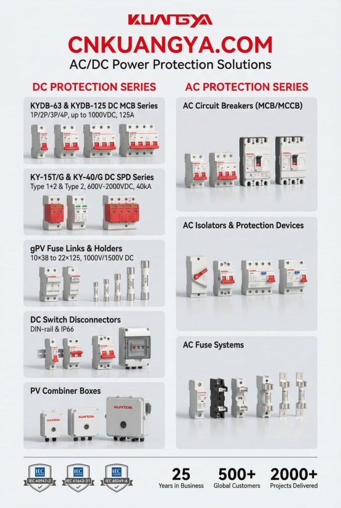
¿Necesita asesoramiento experto en diseño de sistemas de protección? Póngase en contacto con cnkuangya.COM‘para realizar un análisis exhaustivo específico del emplazamiento que optimice la seguridad, la fiabilidad y los costes del ciclo de vida para los parámetros específicos de su instalación.
