Zona industrial de WengYang Yueqing Wenzhou 325000
Horas de trabajo
De lunes a viernes: de 7.00 a 19.00 horas
Fin de semana: 10.00 A 17.00 HORAS
Zona industrial de WengYang Yueqing Wenzhou 325000
Horas de trabajo
De lunes a viernes: de 7.00 a 19.00 horas
Fin de semana: 10.00 A 17.00 HORAS
DC circuit breaker sizing for solar is not simply a matter of matching a breaker to the array’s operating current. A safe selection must also withstand the highest cold-weather open-circuit voltage, carry continuous current without nuisance tripping, protect the cable after derating, interrupt the available fault current, and use the pole configuration approved by the manufacturer.
This five-step guide gives solar EPCs, panel builders, installers, and procurement teams a practical sizing workflow for PV strings, combiner-box outputs, and inverter DC feeders. It is a design aid—not a substitute for the project’s applicable electrical code, module and inverter manuals, or a licensed engineer’s approval.
Alternating current passes through zero every cycle, which helps an AC breaker extinguish an arc. Direct current has no natural zero crossing. A PV breaker therefore needs a DC-specific contact system, arc chute, insulation distance, and approved series-pole arrangement. An AC-only MCB should never be assumed suitable for a solar DC circuit.
The current edition of IEC 60947-2:2024 covers circuit breakers up to 1,500 V DC, while IEC 62548-1:2023, including its 2025 amendment, addresses PV-array wiring, protection, switching, and earthing requirements. Always confirm which standards and local code editions are specified in the project contract.
The calculation changes with the circuit. Before choosing an ampere rating, identify the breaker’s exact duty:
Also confirm whether the breaker is required only for overcurrent protection, for isolation, or for both functions. A device used as an isolator must be explicitly marked and approved for that duty.
For accurate DC circuit breaker sizing for solar, use module open-circuit voltage, not operating voltage. PV module Voc rises as cell temperature falls, so the design voltage must be checked at the site’s lowest expected temperature.
Maximum string voltage = Modules in series × Cold-corrected module Voc
The preferred method is to use the module manufacturer’s temperature coefficient and the minimum design temperature specified for the site. If the inverter design software or local code supplies a correction factor, use that approved method.
A string contains 18 modules. Each module has a Voc of 49.5 V at STC, and the approved cold-weather calculation gives a correction factor of 1.12:
18 × 49.5 V × 1.12 = 997.9 V DC
A 1,000 V DC breaker would leave almost no engineering margin and may be unsuitable once tolerances or project requirements are considered. The designer should review the string length or select a correctly certified higher-voltage protection architecture. Never add pole voltage ratings unless the manufacturer’s wiring diagram specifically permits the poles to be connected in series for that DC rating.
For PV source circuits, start with the module short-circuit current, Isc. For a combiner output, multiply by the number of parallel strings:
Array short-circuit current = Module Isc × Number of parallel strings
Then apply the continuous-current and environmental factors required by the governing code. In NEC-based designs, a commonly used planning calculation is:
Minimum OCPD current = Isc × 1.25 × 1.25 = Isc × 1.56
The first factor establishes maximum PV circuit current; the second accounts for continuous loading of the overcurrent device. Exceptions and 100%-rated equipment can change the result, so the adopted code and equipment listing control the final value. IEC projects use the design and coordination rules specified by IEC 62548-1 and local national adoption rather than blindly applying the NEC multiplier.
Assume one PV string has a module Isc of 13.2 A:
13.2 A × 1.56 = 20.6 A
The next standard rating might be 25 A, but that value is acceptable only if all of the following are true:
En DC circuit breaker sizing for solar, a breaker primarily protects conductors. Its rated current must therefore be no greater than the cable’s allowable ampacity after all corrections. Consider ambient temperature, cable grouping, conduit fill, rooftop temperature, enclosure temperature, and terminal limits.
A useful coordination check is:
Design load current ≤ Breaker rating ≤ Derated cable ampacity
For a PV string, also verify:
Breaker rating ≤ Module maximum series protection rating
If no standard breaker rating fits between the minimum design current and the maximum permitted protection, do not simply choose a larger breaker. Revisit the cable size, string configuration, protective-device type, or module selection.
A correct ampere rating does not guarantee safe fault interruption. Check the breaker’s rated short-circuit breaking capacity at the actual DC voltage. It must exceed the prospective fault current at its installation point.
For ordinary PV strings, current is source-limited, but reverse current from parallel strings changes the available fault level. Battery-coupled systems can produce dramatically higher current. The protective device must be evaluated for the actual source configuration—not selected from current rating alone.
Complete the selection with these field checks:
Este DC circuit breaker sizing for solar example uses three identical strings connected in parallel:
First calculate combined Isc:
13.2 A × 3 = 39.6 A
Using the NEC-style planning factor:
39.6 A × 1.56 = 61.8 A
A 63 A breaker is the first likely standard candidate. It passes the cable check because 63 A is below the cable’s 80 A derated ampacity. The engineer must still verify the device’s DC rating at 842 V, approved pole configuration, breaking capacity, enclosure-temperature derating, and the exact local code calculation.
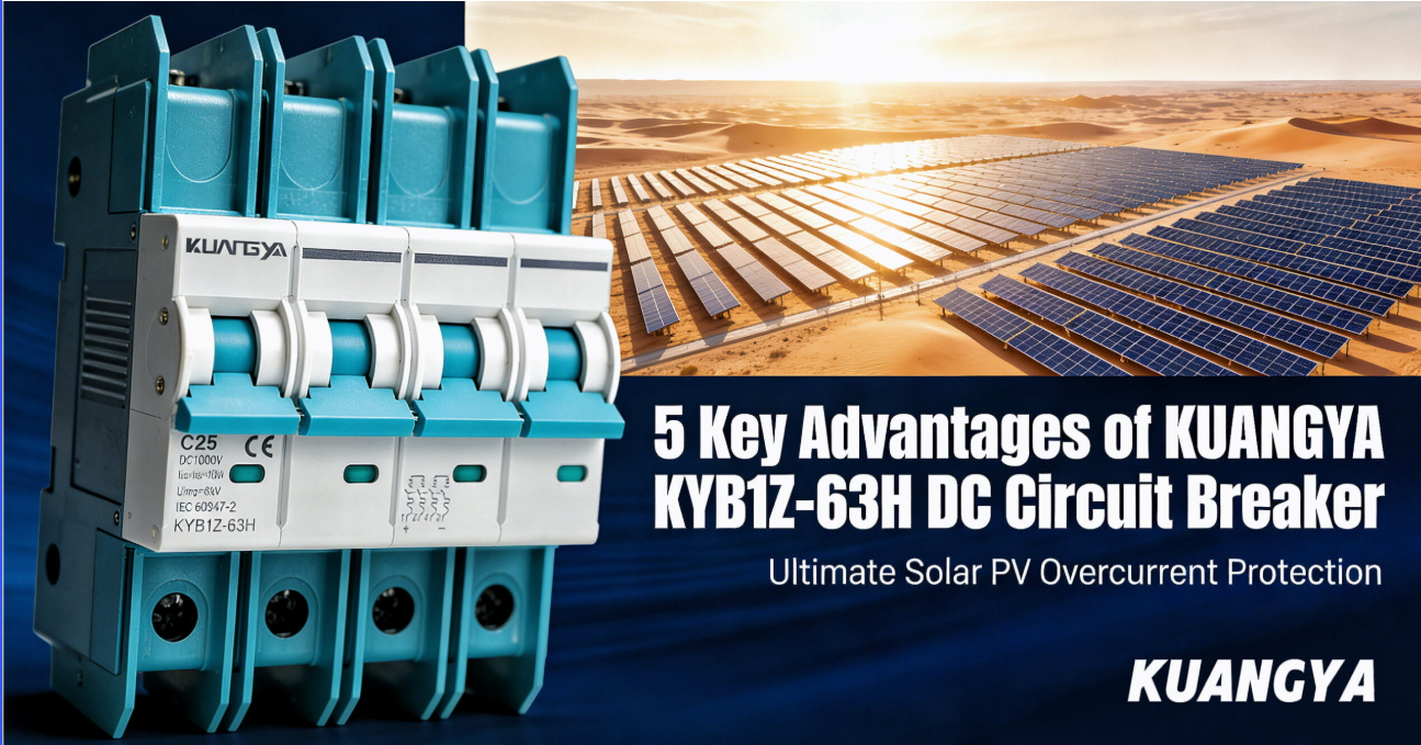
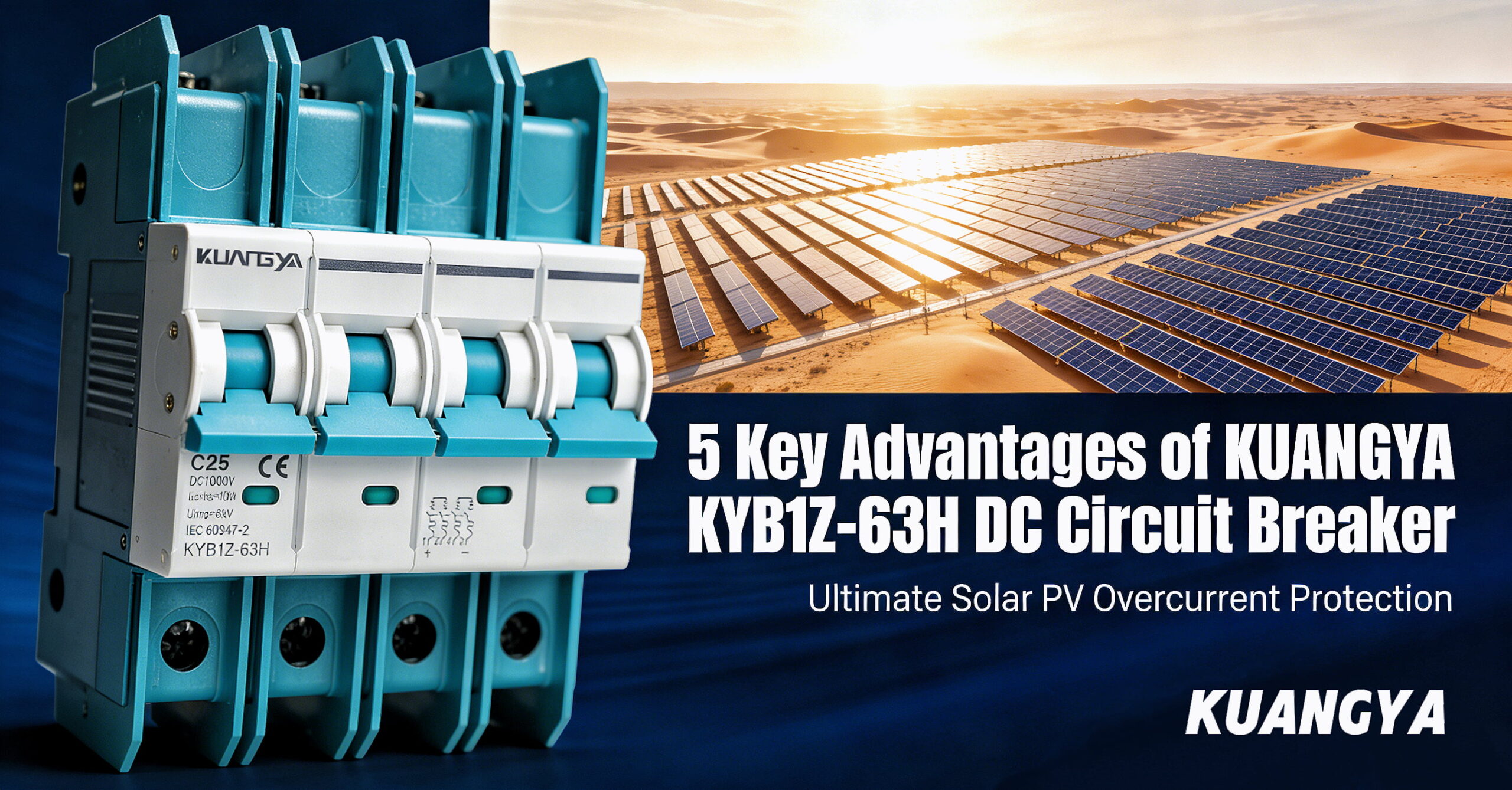
For this range, KUANGYA’s KYDB DC MCB portfolio includes configurations up to 1,000 V DC and 125 A. Model selection must follow the product datasheet and the project’s approved single-line diagram.
Most DC circuit breaker sizing for solar errors come from using the wrong voltage or current basis, or from ignoring site derating.
Before issuing an RFQ for DC circuit breaker sizing for solar, provide the supplier with:
No, unless the manufacturer explicitly provides a DC rating and approved wiring arrangement for that exact device. DC arcs are harder to extinguish, so an AC-only rating is not sufficient.
PV overcurrent calculations generally start with module Isc. Imp is useful for operating analysis but does not replace the code-defined short-circuit-current basis.
Not automatically. Breakers provide resettable protection and switching, while gPV fuses can offer high interrupting performance and specific PV time-current behavior. Many combiner designs coordinate both. Use the approved protection study and equipment listings.
Modern high-current modules often lead to 20 A or 25 A string protection, but there is no universal answer. Correct DC circuit breaker sizing for solar depends on module Isc, the applicable factors, maximum series fuse rating, cable ampacity, ambient temperature, and local code.
Fiable DC circuit breaker sizing for solar requires five linked checks: circuit duty, cold-corrected voltage, code-based design current, cable and module coordination, and verified DC interruption performance. If any one of these checks is skipped, a breaker that looks correct on a parts list may nuisance-trip—or fail to clear a dangerous fault.
KUANGYA supplies DC MCB solutions for residential, commercial, and industrial PV systems, with pole and current options for coordinated DC protection. Contact KUANGYA with your voltage, current, string count, cable size, and applicable standard for model-selection support.
