Zona industrial de WengYang Yueqing Wenzhou 325000
Horas de trabajo
De lunes a viernes: de 7.00 a 19.00 horas
Fin de semana: 10.00 A 17.00 HORAS
Zona industrial de WengYang Yueqing Wenzhou 325000
Horas de trabajo
De lunes a viernes: de 7.00 a 19.00 horas
Fin de semana: 10.00 A 17.00 HORAS

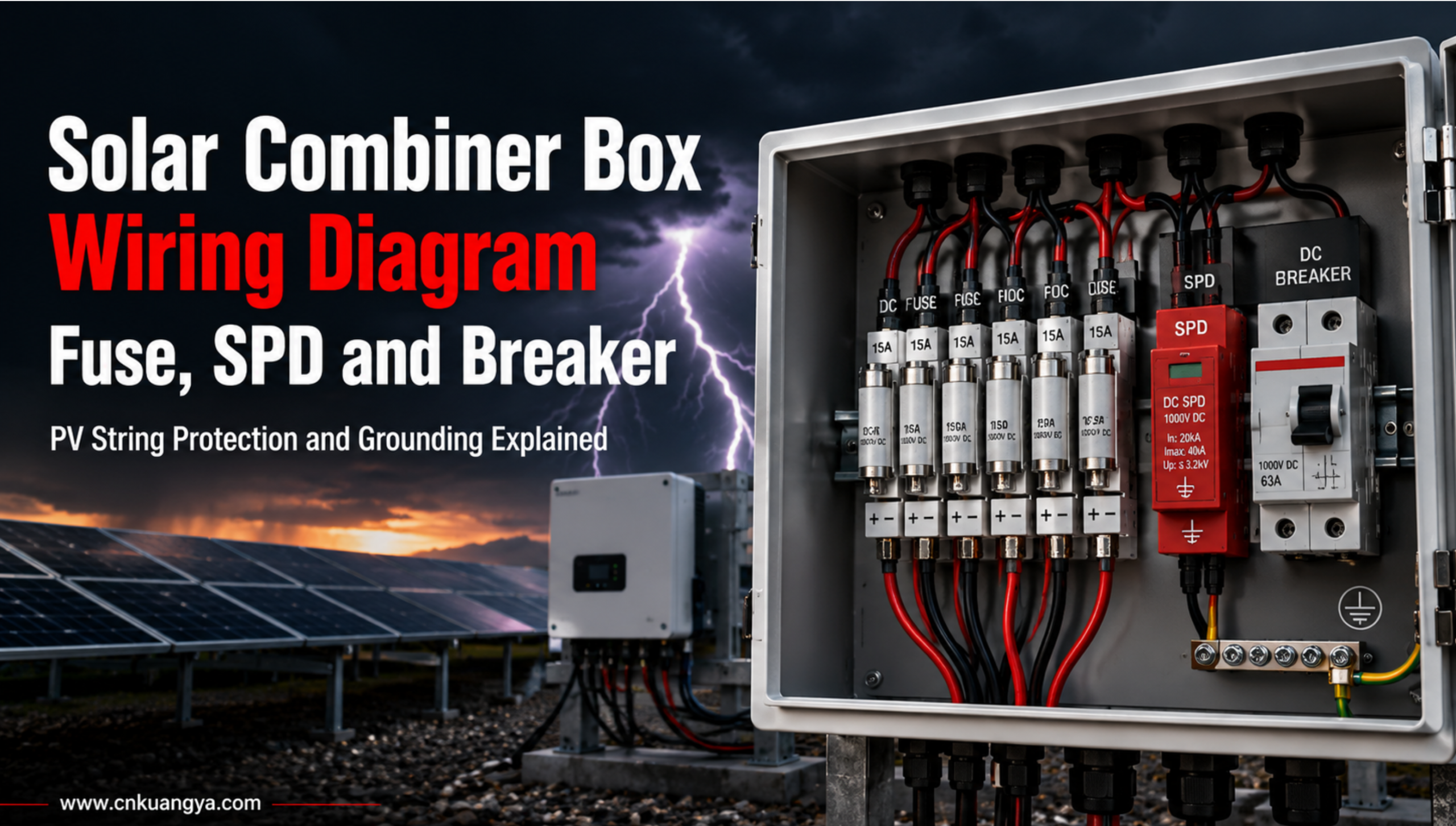
A Solar Combiner Box Wiring Diagram shows how multiple PV strings are connected into one or more DC output circuits before entering the solar inverter.
A complete wiring layout usually includes:
The combiner box is not just a plastic box with wires. In a professional PV system, it is the first DC protection point between the solar panels and the inverter.
If the wiring diagram is wrong, the system may face overheating, blown fuses, SPD failure, inverter damage, arc faults or unexpected shutdown.
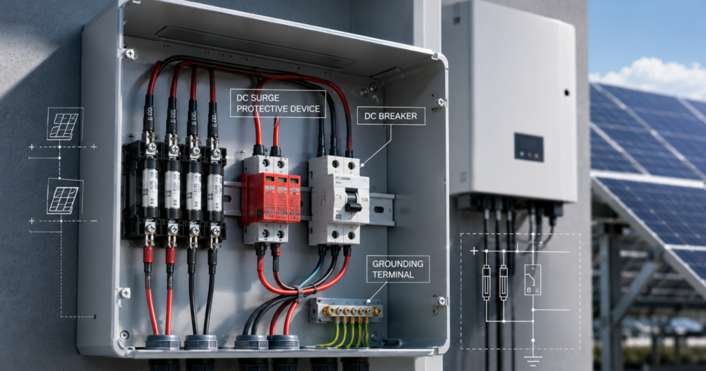
A solar combiner box is an electrical enclosure used to combine multiple photovoltaic strings into one or more DC outputs.
In a solar PV system, panels are connected in series to form strings. Several strings may then be connected in parallel before feeding power to the inverter. The combiner box collects these string outputs, protects them and sends the combined DC power to the inverter.
A typical solar combiner box includes:
| Componente | Función |
|---|---|
| PV string input terminals | Connect positive and negative cables from solar strings |
| Portafusibles gPV | Protect each PV string from reverse current and fault current |
| DC SPD | Discharge surge energy caused by lightning or transient overvoltage |
| DC breaker or isolator | Disconnect DC output during maintenance |
| Barras colectoras | Combine multiple string currents |
| Grounding terminal | Provide protective grounding connection |
| Recinto | Protect internal components from water, dust and UV exposure |
For small residential systems, a separate combiner box may not always be required if the inverter already has enough string inputs and built-in protection.
For commercial, industrial and utility-scale PV systems, a solar combiner box is usually important because it improves wiring organization, protection, maintenance and safety.
Many people think a combiner box is easy: connect all positive wires together, connect all negative wires together, and send them to the inverter.
That is not a safe professional design.
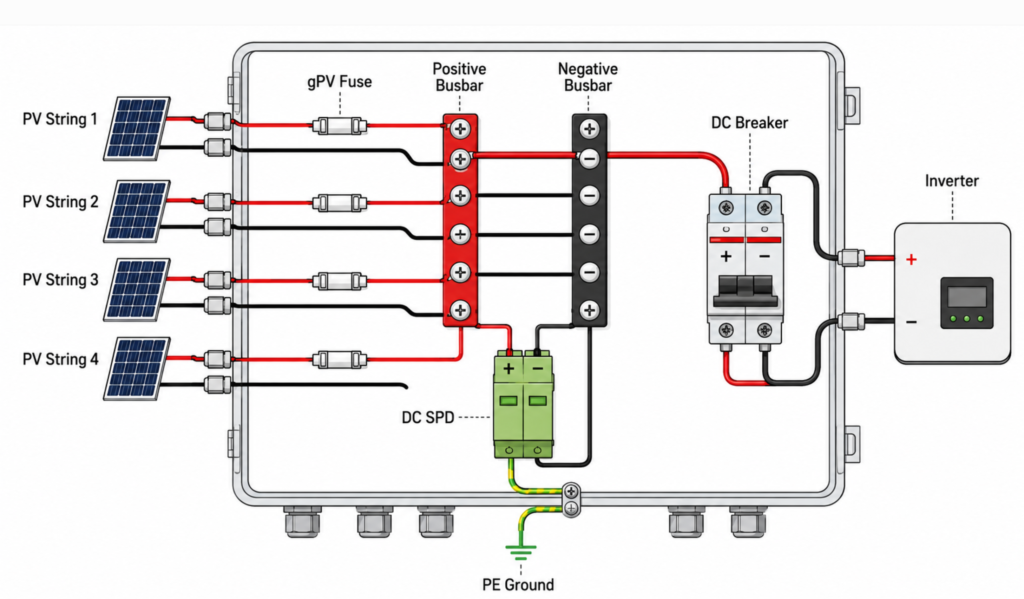
A proper Solar Combiner Box Wiring Diagram must show:
A wrong wiring layout can cause serious problems.
For example, if the SPD is not properly connected to ground, it cannot discharge surge energy effectively. If the fuse rating is too high, it may not protect the string cable correctly. If AC breakers are used in DC circuits, they may not interrupt DC faults safely.
IEC 62548-1:2023 sets out PV array design requirements, including DC array wiring, electrical protection devices, switching and earthing provisions. This is why PV combiner box wiring should be treated as part of system safety design, not just field installation work.
A simplified solar combiner box wiring structure looks like this:
PV String 1 (+) ── Fuse ┐
PV String 2 (+) ── Fuse ├── Positive Busbar ── DC Breaker ── Inverter (+)
PV String 3 (+) ── Fuse ┘

PV String 1 (-) ─────────┐
PV String 2 (-) ─────────├── Negative Busbar ─────────────── Inverter (-)
PV String 3 (-) ─────────┘

DC SPD (+) ── Positive Busbar
DC SPD (-) ── Negative Busbar
DC SPD PE ── Grounding Terminal

Enclosure Ground ── Grounding Terminal ── Earth
This is only a basic diagram. Real project wiring may vary depending on the inverter type, grounding system, number of strings, local code requirements and project specification.
However, the basic protection logic is usually similar:
PV strings enter the combiner box → string fuses protect each input → SPD protects against surge voltage → breaker or isolator disconnects the output → inverter receives the combined DC power.
Each PV string usually has one positive cable and one negative cable.
For example, a 4-string combiner box has:
The wiring diagram should clearly show each input number.
This helps installers avoid wrong polarity, mixed strings or messy cable routing.
Good labeling is especially important for EPC projects because many failures are caused not by the product itself, but by unclear installation and poor field wiring.
Fusible FV (eslabones y portafusibles gPV) | Fusible CC de alto voltaje 1000V/1500V | Kuangya
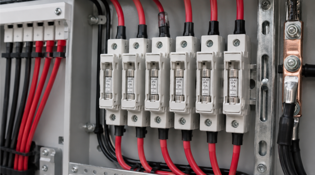
The fuse is one of the most important components inside a solar combiner box.
PV strings are DC circuits. DC current is harder to interrupt than AC current because it does not naturally cross zero. Therefore, ordinary AC fuses should not be used for PV string protection.Portafusibles industrial CA Serie RT18 32A-125A | Kuangya
A proper solar combiner box should use Fusibles gPV designed for photovoltaic systems.
For PV string protection, engineers should select fuses designed specifically for photovoltaic DC circuits. IEC 60269-6 applies to fuse-links for the protection of PV strings and arrays in circuits up to 1,500V DC.
The fuse protects the PV string from reverse current and fault current.
For example, when one string has a fault, current from other parallel strings may flow backward into the faulty string. Without proper fuse protection, the cable or module may overheat.
A professional wiring diagram should show:
For most project quotations, buyers should not simply ask for “a combiner box.” They should ask for the fuse current rating, fuse voltage rating and whether the fuse is gPV type.
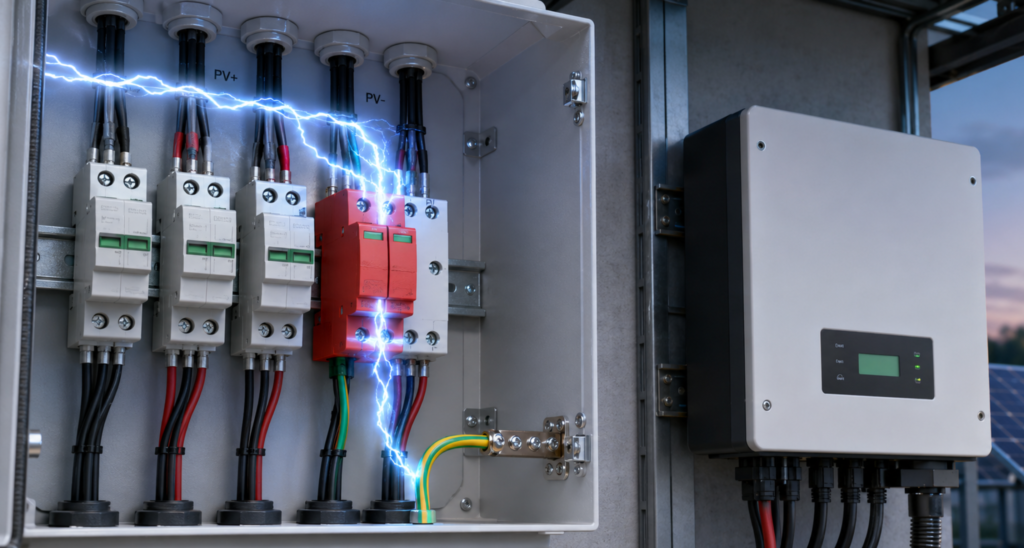
A DC SPD is used to protect the PV system from lightning-induced surge voltage and transient overvoltage.
Solar PV systems are often installed outdoors, on rooftops, open fields, deserts, mountains or industrial sites. Long DC cable runs can pick up surge energy from nearby lightning events.
The DC SPD is usually connected between:
The SPD must be connected with a short and reliable grounding path.
A poor grounding connection can reduce SPD performance.
IEC 61643-31 covers requirements and test methods for low-voltage SPDs used in photovoltaic installations. This is why the SPD inside a combiner box should be selected according to PV system voltage and not treated as a generic low-voltage accessory.
A solar combiner box wiring diagram should show:
For PV systems, common SPD ratings may include 600V DC, 1000V DC and 1500V DC. The final selection must match the system’s maximum DC voltage.
The DC breaker or DC isolator is used to disconnect the combiner box output from the inverter side.
This is important because solar panels continue producing DC voltage when exposed to sunlight. Even if the inverter is turned off, the PV string side may still be energized.
The output disconnect device allows technicians to isolate the combiner box during maintenance.
A wiring diagram should clearly show:
Do not use an AC breaker as a replacement for a DC breaker in a PV combiner box.
DC switching requires specific arc-extinguishing capability. A component that works in AC circuits may not safely interrupt DC voltage.
The busbars collect current from multiple PV strings.
For example, in a 6-string combiner box, six positive inputs may be combined on a positive busbar, and six negative inputs may be combined on a negative busbar.
The busbar must be sized for:
Poor busbar design can lead to overheating, loose connections or arcing.
In a good solar combiner box, busbars should be clearly separated, properly insulated and firmly mounted.
Grounding is not optional.
The grounding terminal connects:
The SPD depends heavily on grounding. If the grounding path is too long, loose or missing, surge protection may be weakened.
A solar combiner box wiring diagram should make the grounding path very clear.
For outdoor projects, grounding terminals should also resist corrosion and maintain reliable connection over time.
A practical wiring sequence usually follows this logic:
Before wiring, confirm:
Do not wire the combiner box before confirming the electrical data.
Connect each string positive cable to the corresponding fuse holder.
Connect each string negative cable to the negative terminal or negative fuse holder, depending on the design.
The installer should check polarity before connection.
Reverse polarity can damage equipment.
Install fuses with correct voltage and current rating.
Do not oversize the fuse just to avoid nuisance blowing.
An oversized fuse may fail to protect the cable during fault conditions.
For systems following NEC-based design, PV source circuit current calculation often uses the module short-circuit current multiplied by 125%. ICC’s 2021 International Solar Energy Provisions state that maximum current shall be the sum of PV module short-circuit current ratings connected in parallel multiplied by 125%.
The final fuse rating should be selected according to applicable standards, cable ampacity, module data and project requirements.
DC SPD (Dispositivo de protección solar contra sobretensiones de CC) | Kuangya
Connect the SPD according to the wiring diagram.
Keep the grounding cable short and direct.
Long wiring can increase residual voltage and reduce surge protection effectiveness.
The SPD should also match the system voltage.
For example, a 1000V DC system should use an SPD suitable for 1000V DC PV application. A 1500V DC system should use a 1500V DC SPD.
Connect the combined positive and negative outputs to the DC breaker or isolator.
Then connect the output cable to the inverter DC input.
Confirm the breaker voltage and current rating.
For high-voltage PV systems, the output device must be DC-rated and suitable for the maximum system voltage.
Connect all grounding points to the main grounding terminal.
This includes:
Grounding should be mechanically secure and corrosion-resistant.
Before energizing the system, check:
A clean inspection process reduces installation mistakes and improves long-term reliability.
This is one of the most dangerous mistakes.
PV systems generate DC power. Fuses, breakers, isolators and SPD must be suitable for DC photovoltaic applications.
AC-rated components may fail to interrupt DC faults safely.
A fuse that is too small may blow frequently.
A fuse that is too large may not protect the cable or string correctly.
The correct fuse rating depends on module Isc, string configuration, cable ampacity, temperature and project standards.
A DC SPD without proper grounding is not real protection.
The grounding conductor should be short, direct and reliable.
Poor grounding can allow surge energy to reach the inverter.
Loose terminals create high resistance.
High resistance creates heat.
Heat creates long-term fire risk.
Every terminal should be tightened according to the specified torque.
Outdoor combiner boxes face rain, humidity, dust and UV exposure.
If the cable gland is not sealed correctly, water may enter the box.
Water ingress can lead to corrosion, insulation faults and short circuits.
Without clear labeling, maintenance becomes difficult.
Each string input, fuse, SPD, breaker and grounding terminal should be clearly marked.
A good wiring diagram should match the real labels inside the box.
Combiner boxes installed in hot outdoor environments may face high internal temperature.
Fuse holders, cables and terminals should be selected with temperature rise in mind.
For desert, rooftop and high-temperature areas, enclosure material and internal spacing are important.
Modern PV systems commonly use 1000V DC or 1500V DC designs.
A 1000V combiner box is commonly used in many commercial and smaller utility systems.
It usually requires:
A 1500V combiner box is often used in larger commercial and utility-scale projects.
It requires:
Do not use 1000V components inside a 1500V combiner box.
The enclosure may look the same, but the electrical stress is different.
When selecting a solar combiner box, check these parameters:
| Selection Item | Qué comprobar |
|---|---|
| String number | 2 in, 4 in, 6 in, 8 in, 12 in, 16 in |
| Tensión del sistema | 600V, 1000V or 1500V DC |
| Fuse type | gPV fuse for PV DC application |
| Fuse current | Match PV string current and cable capacity |
| SPD rating | Match PV system voltage and grounding type |
| Breaker or isolator | DC-rated, correct voltage and current |
| Recinto | IP65 or IP66 for outdoor use |
| Cable gland | Correct size and sealing performance |
| Conexión a tierra | Clear PE terminal and bonding design |
| Diagrama | Supplier should provide wiring diagram |
| OEM | Logo, label, component brand and layout customization |
A professional supplier should not only quote the box price. They should also confirm the system voltage, string number, fuse rating, SPD rating, output current and enclosure requirement.
Before ordering, send these questions to the supplier:
This checklist helps buyers avoid unclear quotations.
It also helps EPC contractors reduce project risk before installation.
For EPC contractors, the wiring diagram is not just a drawing.
It is a communication tool between:
A clear solar combiner box wiring diagram can reduce:
For overseas projects, the wiring diagram should be simple, clear and easy to understand.
Recommended documentation includes:
This makes the combiner box easier to install and easier to maintain.
KUANGYA provides electrical protection components and customized solutions for solar PV systems, energy storage projects and industrial power distribution.
For solar combiner box applications, KUANGYA can support:
A reliable solar combiner box should not be selected only by price.
The real value is in the complete protection design:
PV string fuse + DC SPD + DC breaker + grounding + outdoor enclosure.
When these parts work together, the combiner box can help protect the inverter, reduce DC-side risk and improve long-term system reliability.
A solar combiner box wiring diagram shows how PV string inputs, fuses, SPD, breaker, busbars and grounding terminals are connected inside the combiner box.
You may need a solar combiner box when multiple PV strings must be combined before the inverter, especially in commercial, industrial and utility-scale systems.
A solar combiner box should use DC-rated gPV fuses designed for photovoltaic systems.
A DC SPD helps discharge lightning-induced surge voltage and reduce the risk of inverter damage.
No. PV systems use DC circuits, so the breaker or isolator must be DC-rated and suitable for the system voltage.
A 1500V combiner box uses components with higher DC voltage ratings and stricter insulation spacing than a 1000V combiner box.
The SPD is usually connected between the DC positive/negative circuits and PE grounding terminal, depending on the SPD design and system configuration.
IP65 or IP66 is commonly used for outdoor PV combiner boxes.
Common causes include loose terminals, wrong fuse rating, SPD failure, water ingress, poor grounding, overheating and poor-quality components.
Yes. String number, voltage rating, fuse current, SPD rating, enclosure size, cable glands, wiring diagram and OEM logo can be customized.
A Solar Combiner Box Wiring Diagram is more than a simple connection drawing.
It shows how the DC side of a solar PV system is protected, organized and maintained.
A professional combiner box should include correctly selected gPV fuses, DC SPD, DC breaker or isolator, grounding terminal, busbars and an outdoor-rated enclosure.
For EPC contractors, distributors and solar project buyers, the combiner box should never be selected only by price.
The right wiring design can protect the inverter, reduce fire risk, simplify maintenance and improve the long-term reliability of the solar PV system.

