Zona industrial de WengYang Yueqing Wenzhou 325000
Horas de trabajo
De lunes a viernes: de 7.00 a 19.00 horas
Fin de semana: 10.00 A 17.00 HORAS
Zona industrial de WengYang Yueqing Wenzhou 325000
Horas de trabajo
De lunes a viernes: de 7.00 a 19.00 horas
Fin de semana: 10.00 A 17.00 HORAS
Last Updated: July 3, 2026 | Version 1.0
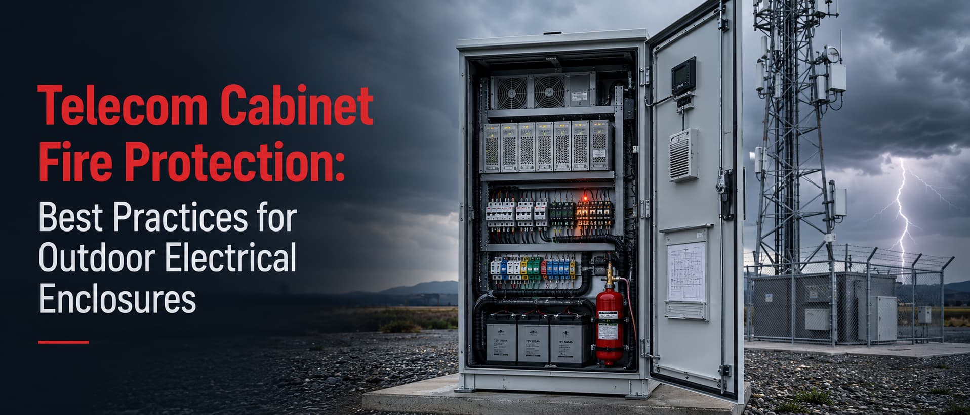
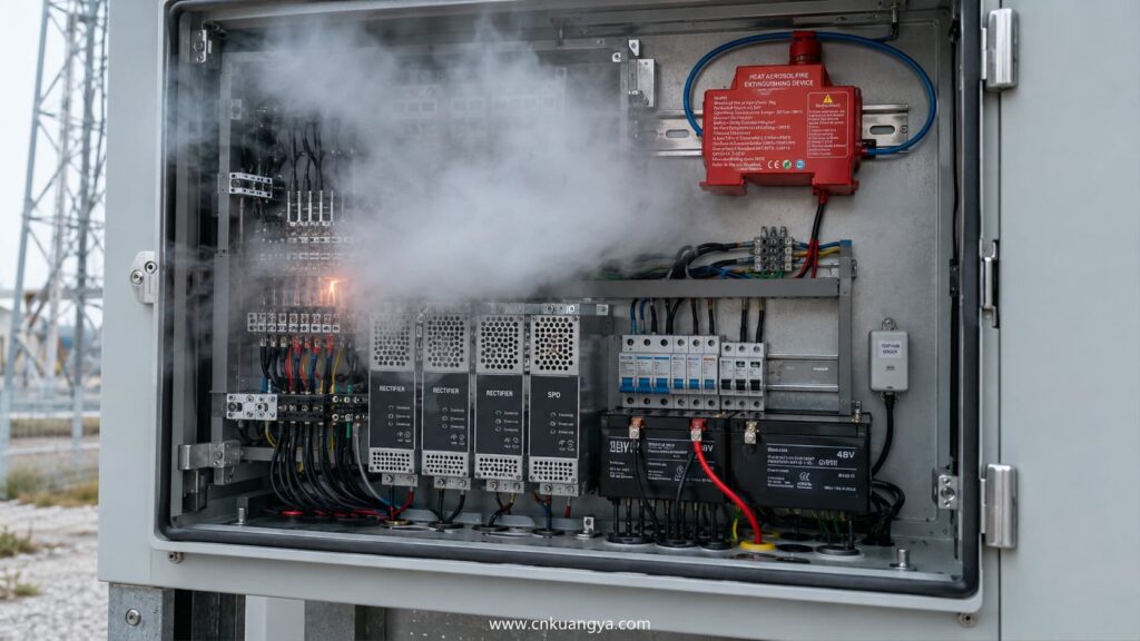
Outdoor telecom cabinets support mobile networks, fiber access systems, private 5G infrastructure, traffic communications, smart-city equipment, and remote industrial networks. Their compact construction improves deployment efficiency, but it also concentrates power supplies, batteries, surge protection devices, communication electronics, cables, and cooling components within a limited enclosure.
A minor electrical fault inside one cabinet can interrupt an entire communications node. In remote or unmanned locations, a loose terminal, deteriorated battery connection, failed fan, damaged surge protective device, or water-contaminated connector may continue developing for hours before a technician arrives.
Efectivo Telecom Cabinet Fire Protection therefore requires more than installing a fire extinguisher. It must combine enclosure engineering, thermal management, overcurrent protection, surge protection, battery safety, early detection, automatic suppression, remote alarms, and disciplined maintenance.
NFPA 76 addresses fire protection for facilities that provide telephone, data, internet, wireless, and video transmission services. Although an outdoor cabinet is smaller than a conventional telecommunications building, the same basic principle applies: communication availability depends on controlling ignition sources before they become service-affecting events.
Telecom Cabinet Fire Protection is the coordinated control of ignition, fire growth, equipment damage, and network interruption inside or around a telecommunications enclosure.
An effective Telecom Cabinet Fire Protection strategy must address electrical faults, battery hazards, surge exposure, thermal accumulation, water ingress, and delayed maintenance as one connected risk system.
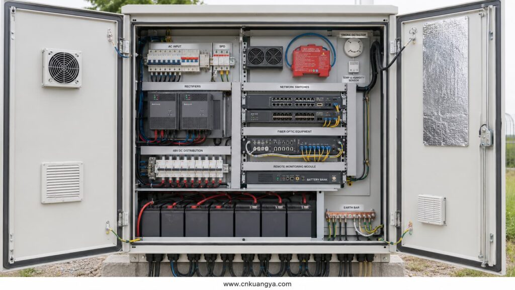
The protected equipment may include rectifiers, AC distribution units, DC power systems, network switches, baseband units, optical transmission equipment, batteries, air-conditioning components, and remote monitoring devices.
In a 5G deployment, these systems are frequently placed closer to users. Equipment may be installed beside roads, on rooftops, inside industrial facilities, near utility infrastructure, or at remote base-station sites.
This distributed architecture reduces the physical size of each node. It does not reduce the operational importance of the node.
One outdoor cabinet may serve several radio units, fiber distribution points, surveillance systems, traffic-control devices, or industrial communication terminals.
If its DC power system fails, every connected communication device can be lost simultaneously. If the cabinet contains backup batteries, the event may continue even after the upstream AC supply has been disconnected.
A cabinet fire may therefore create several consequences at the same time:
| Consecuencia | Operational Impact |
|---|---|
| Loss of rectifier or DC distribution | Immediate shutdown of active telecom equipment |
| Battery damage | Loss of backup runtime during grid failure |
| Fiber or copper cable damage | Isolation of downstream nodes |
| Smoke contamination | Corrosion and failure of apparently undamaged electronics |
| Cooling-system failure | Secondary overheating after partial recovery |
| Damaged alarm circuits | Loss of visibility from the network operations center |
| External flame spread | Damage to nearby cabinets, cables, vegetation, or structures |
| Emergency communication interruption | Reduced access to telephone, data, or public safety services |
The financial cost of replacing a cabinet is often smaller than the cost of the network interruption. Service-level penalties, emergency repair work, customer complaints, traffic diversion, and loss of public-safety communications can dominate the final loss.
Large telecom facility incidents are not identical to street-cabinet fires. However, they demonstrate how a localized ignition can become a regional communication problem.
| Incident | Verified Consequence | Engineering Lesson |
|---|---|---|
| KT Ahyeon, Seoul, 2018 | A fire in a basement telecommunications facility damaged communication equipment and cables. Mobile, internet, and IPTV services were disrupted in central Seoul, and extinguishing operations took approximately ten hours. | Avoid excessive concentration of critical circuits, improve fire compartmentation, and detect developing faults before smoke spreads through cable routes. |
| Ramses Telecom Facility, Cairo, 2025 | A major fire caused deaths, injuries, and widespread communication disruption. Early reporting showed national internet connectivity falling to about 62% of normal levels. | Electrical rooms and telecom power systems need early isolation, monitored protection, effective detection, and resilient routing. |
| AT&T Facility, Gardena, 2025 | An external rubbish or vegetation fire spread into the telecom structure, causing an explosion, roof damage, and interruptions to 911, cellular, and internet services. | Outdoor Cabinet Fire Protection must consider external flame exposure, vegetation control, combustible storage, cable-entry sealing, and cabinet location—not only internal faults. |
These incidents support a clear conclusion: a telecom fire is not merely an equipment-maintenance problem. It can become a network resilience and public-safety problem.
A modern 5G cabinet may contain more power-dense electronics than an older passive distribution enclosure.
Rectifiers, edge-computing hardware, power-over-Ethernet equipment, battery charging systems, and active cooling can operate continuously. Heat generation remains present even when ambient conditions are already severe.
The transition from large equipment rooms to distributed edge sites also increases the number of locations that must be inspected. A weak maintenance process is multiplied across hundreds or thousands of enclosures.
The most effective strategy is therefore not to rely on technicians noticing a problem. The cabinet must monitor itself and report abnormal conditions before service is lost.
For distributed 5G infrastructure, Telecom Cabinet Fire Protection must therefore combine local automatic response with remote alarm reporting and network-level redundancy.
A reliable Telecom Cabinet Fire Protection design begins by identifying how electrical, thermal, environmental, and battery-related failures can develop inside the same enclosure.
Most cabinet fires develop through a sequence rather than a single sudden event.
A connection becomes loose. Resistance increases. Local temperature rises. Insulation deteriorates. Arcing or carbon tracking begins. Nearby polymeric materials ignite, and ventilation airflow distributes heat and smoke through the enclosure.
Understanding this sequence allows engineers to interrupt it at several points.
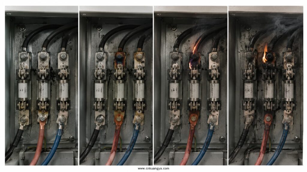
Loose terminals are one of the most preventable ignition sources in electrical enclosures.
A conductor may appear mechanically connected while only part of its surface carries current. Increased contact resistance produces concentrated heating at the terminal, lug, fuse holder, breaker, busbar, or battery connection.
This condition may not immediately operate an overcurrent protective device. Current can remain within the nominal circuit rating while the connection temperature continues rising.
Recommended controls include:
A fuse or breaker cannot compensate for poor workmanship. It protects against defined current conditions, not every high-resistance joint.
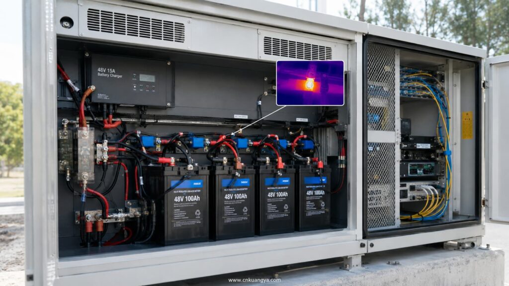
Telecom sites commonly use 48 V DC systems, although other DC voltages may be present in battery, solar-assisted, monitoring, or auxiliary circuits.
A short circuit can release substantial energy because batteries and rectifiers may provide high fault current. The available current depends on battery impedance, conductor length, rectifier capacity, and protective-device coordination.
DC arcs require particular attention because current does not cross zero every half-cycle as it does in an AC circuit. An established DC arc may therefore remain stable if the circuit voltage and current are sufficient.
The practical control is to minimize fault energy:
A protective device should never be selected only by its current rating. Voltage rating, breaking capacity, time-current characteristic, conductor ampacity, and load inrush must also be evaluated.
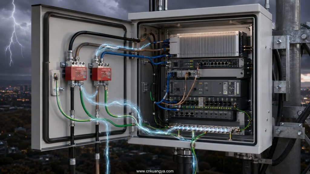
Outdoor telecom sites are exposed to long power feeders, elevated structures, antenna systems, metallic communication cables, grounding conductors, and nearby lightning electromagnetic fields.
A surge does not need to create an immediate visible fire. It may weaken a power supply, puncture insulation, damage an SPD, or create carbonized tracking that fails later.
IEC 62305-4:2024 addresses surge protection measures intended to reduce permanent failure of electrical and electronic systems caused by lightning electromagnetic impulse. CEI 61643-11:2025 covers SPDs connected to AC low-voltage power systems, while IEC 61643-21 applies to protection devices used on telecommunications and signalling networks.
This means SPD for Telecom should be treated as a coordinated system rather than one device at the AC incomer.
Backup batteries improve network availability, but they also add stored electrical and chemical energy.
Lead-acid batteries may create hazards involving short-circuit current, electrolyte, charging abnormalities, and gas emission. IEC 62485-2 covers safety measures for stationary battery installations, including electrical, gas-emission, and electrolyte hazards.
Stationary lithium-ion batteries require controls for cell safety, charging, temperature, mechanical damage, and battery-management functions. IEC 62485-5 addresses safe operation of stationary lithium-ion batteries, while IEC 62619:2022 specifies safety requirements and tests for industrial lithium cells and batteries.
Battery protection should include:
A cabinet suppression device should not be presented as a substitute for battery safety engineering. In particular, aerosol discharge may suppress surrounding flames but cannot be assumed to stop uncontrolled thermal propagation inside a lithium battery module.
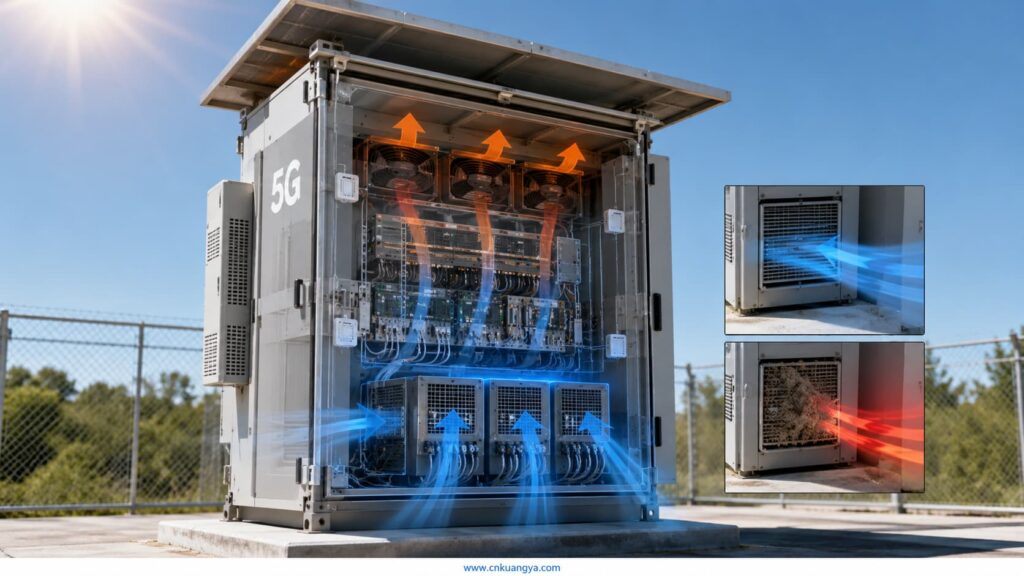
Outdoor cabinets are affected by solar radiation, ambient temperature, internal power dissipation, blocked filters, fan failure, refrigerant-system faults, and recirculated hot air.
ETSI ES 203 156 recommends designing an outdoor enclosure so that the temperature difference between equipment inlet air and ambient air remains as small as possible, with a value below approximately 10 K recommended under maximum operating conditions.
This does not mean every cabinet can remain within a 10 K difference. It means the thermal design should be measured and verified rather than assumed.
A basic thermal review should document:
| Parámetro | Design Question |
|---|---|
| Internal heat load | How many watts are released by rectifiers, radios, switches, batteries, and auxiliary equipment? |
| Maximum ambient temperature | Is the value based on historical site data or a generic catalogue rating? |
| Solar gain | Is the cabinet exposed to direct afternoon sun? |
| Cooling capacity | Is capacity stated at the actual maximum ambient temperature? |
| Airflow route | Can cables or equipment obstruct the intended inlet and return path? |
| Filter condition | How quickly will dust, insects, salt, or vegetation block the filter? |
| Alarm threshold | Will the NOC receive a warning before equipment reaches shutdown temperature? |
| Failure mode | What happens when one fan or cooling unit fails? |
Thermal protection should use at least two alarm levels where practical. The first level requests maintenance, while the second level initiates controlled load reduction or shutdown.
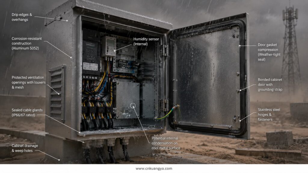
IEC 60529 uses the IP Code to classify an enclosure’s resistance to access, solid-object intrusion, dust, and water. An IP rating is valuable, but it does not prove that the complete installed cabinet will remain dry under every field condition.
Cable glands, door seals, ventilation openings, unused conduit entries, roof joints, and maintenance damage can reduce the protection of the finished assembly.
Condensation is a separate concern. A cabinet can be well sealed and still develop internal moisture when temperature changes cause humid air to reach its dew point.
ANSI/NEMA 250 covers several indoor and outdoor enclosure types, including Types 3R, 4, and 4X. Its published scope also notes that the standard does not by itself cover every internal condition, including condensation, thermal damage, icing, corrosion, or contamination entering through unsealed openings.
Therefore, an IP65 or NEMA 4X label should not end the engineering review.
Outdoor communication cabinets may be installed near vegetation, parked vehicles, waste containers, wooden structures, fuel systems, or public-access areas.
An external fire can heat the enclosure, damage cable insulation, deform seals, ignite polymeric components, or enter through ventilation openings.
Recommended site controls include:
The Gardena incident demonstrates that a fire beginning outside communications equipment can still interrupt critical services. External exposure must therefore be part of Communication Cabinet Safety planning.
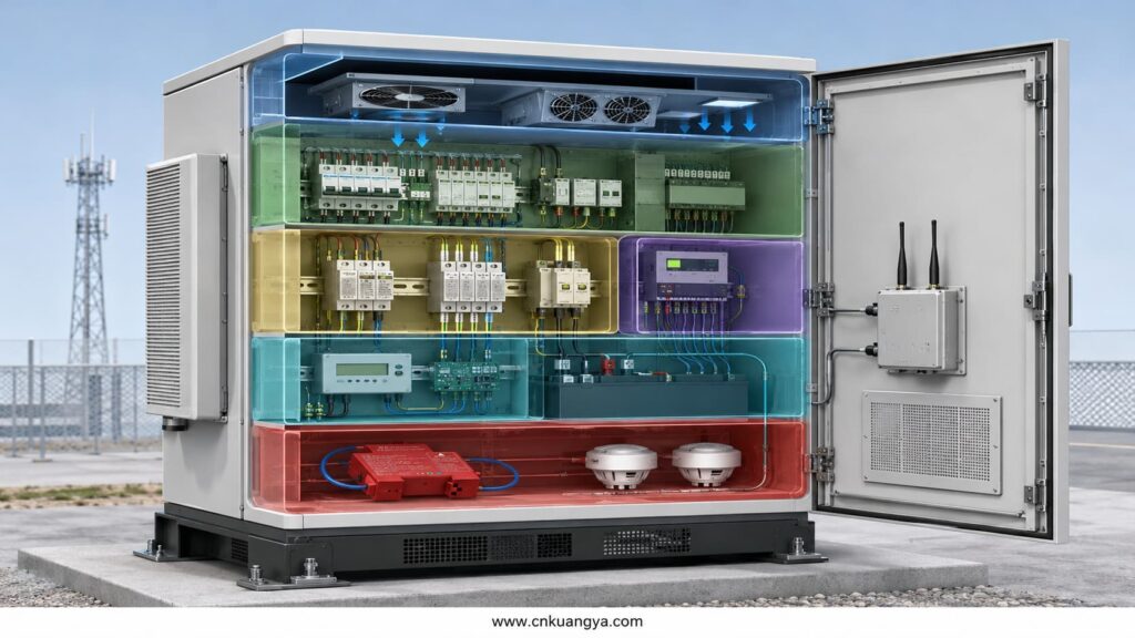
No single component can provide complete Telecom Cabinet Fire Protection.
The strongest Telecom Cabinet Fire Protection system combines enclosure design, overcurrent protection, surge protection, battery monitoring, early detection, automatic suppression, and remote alarm transmission.
A reliable design uses multiple independent layers. Each layer should reduce either the probability of ignition, the speed of fire growth, the duration of the event, or the consequence to the network.
The enclosure should be selected according to the actual installation environment.
IP55 may be suitable for some protected outdoor locations. IP65 or IP66 may be more appropriate where severe dust, wind-driven rain, water jets, or exposed industrial conditions are expected.
For North American projects, NEMA 3R, NEMA 4, or NEMA 4X may be specified according to rain, hose-directed water, corrosion, icing, and project requirements.
IP and NEMA ratings should not be treated as interchangeable labels. Their test scopes and environmental considerations are not identical.
The finished assembly must also preserve the rating after:
A high-rated empty enclosure can become a poorly sealed installed cabinet.
Thermal management should be calculated for normal operation, maximum traffic loading, high ambient temperature, and cooling-system failure.
Natural ventilation may be adequate for low-power cabinets. Fan-assisted ventilation offers more heat removal but introduces filters, moving components, and external air contamination.
Heat exchangers separate internal and external airflow. Air conditioning provides greater control but increases energy use, maintenance requirements, condensate management, and mechanical complexity.
| Cooling Method | Main Advantage | Main Fire-Protection Concern |
|---|---|---|
| Natural convection | Simple and low maintenance | Limited cooling during high solar or internal heat loads |
| Filtered fan ventilation | Economical heat removal | Dust loading, fan failure, and smoke or flame entry |
| Air-to-air heat exchanger | Separated internal airflow | Fan condition and heat-exchanger fouling |
| Compressor air conditioning | Strong temperature control | Refrigerant system, condensate, high power demand, and maintenance |
| Thermoelectric cooling | No compressor and compact format | Lower efficiency and limited high-load capability |
Humidity sensors should be installed where condensation is realistic. Anti-condensation heaters, controlled ventilation, drainage, insulation, or membrane vents may be required depending on the climate.
The objective of overcurrent protection is not simply to prevent conductor overheating. It is to disconnect a fault before the fault can develop into sustained arcing, enclosure damage, or ignition.
Each incoming and outgoing circuit should be documented in a protection schedule.
The schedule should identify:
Battery circuits need special attention because the source can continue supplying fault current after AC isolation.
A battery fuse should be placed sufficiently close to the positive terminal to minimize the length of unprotected conductor. The mounting position must also allow safe replacement without accidental short-circuit contact.
A complete surge concept should map every conductive path entering or leaving the cabinet.
Typical paths include:
Fiber-optic data transmission does not normally conduct a surge through the optical fiber itself. However, metallic armor, tracer wires, power conductors, and equipment bonding can still create surge paths.
IEC 61643-22 provides principles for selecting, locating, operating, and coordinating SPDs connected to telecommunications and signalling networks. It also addresses multiservice devices that protect signal and power conductors within one assembly.
An outdoor cabinet should report developing faults before visible fire.
Useful monitoring points include:
| Sensor or Alarm | Condition Detected |
|---|---|
| Temperature sensor | General overheating or cooling failure |
| Terminal temperature sensor | Localized heating at busbars, breakers, or battery connections |
| Smoke detector | Early combustion products |
| Heat detector | Rapid temperature rise or high fixed temperature |
| Humidity sensor | Condensation risk |
| Water sensor | Ingress or condensate leakage |
| SPD remote contact | End-of-life or disconnected SPD |
| DC undervoltage alarm | Rectifier or battery problem |
| Battery temperature alarm | Charging fault or cell deterioration |
| Fan tachometer alarm | Loss of airflow |
| Door switch | Unauthorized access or incomplete closure |
| Suppression-system contact | Activation or system fault |
Alarm values should be actionable. A network operations center should know whether an alarm requires observation, planned maintenance, immediate dispatch, or remote shutdown.
Alarm overload is also dangerous. If technicians receive repeated low-value alarms, genuine precursors may be ignored.
Fire Suppression for Outdoor Cabinets is the final active layer after prevention and detection.
A compact suppression device can discharge inside the enclosure when a defined thermal or electrical signal is reached. Its objective is to suppress a small developing fire before it damages the entire cabinet or spreads through cable routes.
Condensed aerosol systems are covered by ISO 15779, which addresses system components, design, installation, testing, maintenance, safety, and suitable fire applications. NFPA 2010 provides minimum requirements for fixed aerosol fire-extinguishing systems.
A suppression device must be engineered as part of the cabinet. It should not be added as an unverified accessory after the enclosure has been completed.
Fire protection reduces the probability and severity of failure. Network design reduces the consequence when protection is unsuccessful.
Critical sites may need:
Telecom Equipment Protection is incomplete when it protects hardware but ignores service continuity.
Surge protection is a preventive layer within a complete Telecom Cabinet Fire Protection strategy because transient damage can create immediate faults or weaken components that fail later.
A surge protective device limits transient voltage and diverts surge current away from sensitive equipment.
The word “limits” is important. An SPD does not eliminate all voltage, and its performance depends on correct selection, conductor routing, bonding, earthing, and coordination.
Before selecting an SPD, draw the cabinet and mark every metallic conductor crossing the enclosure boundary.
For each conductor, identify:
A device selected only from the label “telecom SPD” may not support the required signal bandwidth or PoE current.
For an AC-powered cabinet, the incoming SPD should be selected according to the supply configuration, nominal voltage, maximum continuous operating voltage, expected surge environment, and upstream protection.
IEC 61643-11:2025 applies to SPDs connected to AC low-voltage systems for protection against lightning-related and other transient overvoltages. IEC 61643-12 provides selection, application, location, and coordination principles for these devices.
Key parameters include:
| Parámetro | Engineering Meaning |
|---|---|
| Uc or MCOV | Maximum continuous voltage that can be applied without unacceptable operation |
| Arriba | Voltage protection level presented to downstream equipment under defined test conditions |
| En | Nominal discharge current used for defined repetitive test performance |
| Imax | Maximum discharge current for applicable SPD classifications |
| Iimp | Impulse current capability associated with high-energy lightning-current exposure |
| Backup protection | Fuse or breaker required to safely disconnect a failed SPD |
| Short-circuit rating | Ability of the SPD assembly to operate safely under available fault current |
| Remote contact | Signal indicating end-of-life or disconnection status |
A lower Up value is useful only when the SPD remains compatible with the operating voltage and system configuration.
DC circuits can receive surges through external solar supplies, long DC feeders, remote power systems, or bonding potential differences.
A DC SPD must be designed and rated for the actual DC voltage. An AC-only SPD should not be installed on a DC circuit unless the manufacturer explicitly approves that application and rating.
IEC 61643-41:2025 covers SPDs connected to DC power circuits and equipment rated up to 1,500 V DC.
For conventional short internal battery wiring, overcurrent protection and bonding may be more important than a separate SPD. Long outdoor DC cables require a more detailed surge assessment.
Copper data and signalling cables can carry destructive transient voltage directly to Ethernet switches, controllers, monitoring units, and radio equipment.
The protective device must preserve:
Installing an unsuitable SPD can degrade network performance even when no surge occurs.
The line SPD should be mounted close to the cabinet entry point. Its earth connection should be short and direct, while unprotected and protected conductors should be physically separated.
A Type 1 or high-energy SPD at the service entrance and a Type 2 SPD inside the cabinet may need coordination.
The downstream SPD should not receive more energy than it can safely handle. Cable length, conductor inductance, decoupling components, and manufacturer coordination data influence energy sharing.
Sensitive electronic equipment may also require a final protection stage close to its terminals.
The correct sequence is:
High-energy diversion → distribution-level limitation → equipment-level fine protection
This layered concept is more reliable than selecting one large SPD and expecting it to protect every circuit.
Long connection conductors add inductive voltage during a surge.
Even a high-quality SPD can provide poor effective protection if its phase, neutral, or protective-earth leads form long loops.
Recommended installation practice includes:
The effective protective level at the equipment is the SPD residual voltage plus voltage developed across its connecting conductors.
Outdoor sites may operate for months without inspection.
An SPD that has reached end-of-life can leave the cabinet unprotected while the telecom equipment continues operating normally.
For critical sites, specify:
An SPD status alarm should identify the cabinet and circuit, not merely report a generic site fault.
Automatic suppression is the final active layer of Telecom Cabinet Fire Protection after prevention, monitoring, surge control, and electrical isolation have been addressed.
En correct suppression technology depends on the fire hazard, cabinet volume, ventilation, environmental limits, maintenance capability, and equipment value.
There is no universal extinguisher that is ideal for every outdoor enclosure.
| Tecnología | Ventajas | Limitations in Telecom Cabinets |
|---|---|---|
| Condensed aerosol | Compact, no piping, rapid local discharge, suitable for many enclosed electrical applications | Residue compatibility, hot discharge clearances, enclosure leakage, and limited cooling must be assessed |
| Clean agent | Low residue and strong compatibility with electronics when correctly designed | Requires adequate agent quantity, pressure storage or piping, and control of enclosure leakage |
| Water mist | Cooling capability and fire control for selected hazards | Water compatibility, freezing, drainage, corrosion, and electrical design require evaluation |
| Dry chemical powder | Strong knockdown performance | Heavy contamination can make telecom equipment uneconomical to recover |
| CO₂ | Effective for certain enclosed hazards | Serious personnel exposure risk and enclosure integrity requirements |
| Passive fire-resistant compartment | No activation mechanism | Limits spread but does not automatically extinguish the source |
For a small, normally unoccupied electrical compartment, a compact aerosol system may offer a practical balance of installation space and automatic response.
The final choice must still be approved for the specific hazard and jurisdiction.
The external cabinet dimensions are not always the correct basis for suppression selection.
Engineers should determine:
Using only cabinet width × height × depth can overestimate or underestimate actual agent distribution.
If a cabinet contains a sealed electronics compartment and a separately ventilated battery compartment, each area may require an independent protection strategy.
Electrical insulation, polymeric cable materials, circuit boards, rectifiers, filters, and fans present different burning characteristics.
Battery chemistry also changes the hazard.
Aerosol may suppress flames involving cable insulation or electrical components after electrical isolation. It should not be assumed to cool a lithium cell sufficiently to prevent re-ignition or propagation.
For a cabinet with significant lithium battery capacity, the design should prioritize:
Common activation methods include:
A fixed-temperature device is simple but may respond later than a sensitive smoke-detection system.
Electrical activation can provide earlier response and remote status, but it requires a dependable detection circuit, supervised wiring, and backup power.
The activation temperature must remain above the highest credible normal cabinet temperature. A device that activates during solar heating or cooling failure creates its own service outage.
A fan can remove suppression agent from the enclosure and supply oxygen to the fire.
Where compatible with the system design, suppression activation should initiate a defined sequence:
Battery isolation requires special engineering. Disconnecting the AC supply does not remove energy from battery conductors or cells.
The suppression supplier should provide documented information on:
Do not rely only on the statement “safe for electronics.”
Engineers should determine whether discharge residue can affect connectors, cooling fans, optical interfaces, high-frequency circuits, or energized surfaces under the project’s humidity conditions.
Kuangya compact aerosol fire-suppression devices can be evaluated for small electrical and telecom enclosure applications where space is limited.
The product should be selected only after confirming the cabinet’s protected volume, internal airflow, operating temperature, ignition hazards, mounting clearances, activation method, and required certification.
Kuangya can also support a coordinated cabinet protection package that combines:
Final system acceptance remains the responsibility of the cabinet designer, system integrator, project engineer, and local authority having jurisdiction.
A technically correct design can still fail because of poor installation or neglected maintenance.
Long-term Telecom Cabinet Fire Protection therefore depends on verified installation quality, documented inspections, alarm testing, and corrective maintenance.
Outdoor Cabinet Fire Protection should therefore be managed through the full project lifecycle.
Before energization, verify the following:
| Elemento de inspección | Acceptance Requirement |
|---|---|
| Cabinet foundation | Stable, level, drained, and protected from flooding |
| External clearance | No combustible storage or restricted ventilation |
| Cable entry | Correct glands, seals, bending radius, and strain relief |
| Door sealing | Continuous gasket compression and functioning locks |
| Earthing | Bonding continuity verified between door, frame, earth bar, and external earth |
| Terminales | Correct conductor size, lug type, polarity, and torque |
| Fuses and breakers | Correct AC/DC rating, breaking capacity, and circuit identification |
| SPD | Correct voltage, system configuration, backup protection, and short lead length |
| Batteries | Secure mounting, insulated terminals, fuse, monitoring, and ventilation |
| Cooling | Airflow direction, filter installation, alarm function, and condensate control |
| Detección | Sensor location and alarm test |
| Suppression | Correct orientation, protected volume, clearances, and activation circuit |
| Remote alarm | Verified at the network operations center |
| Documentación | Updated schematic, settings, serial numbers, and photographs |
Commissioning should simulate realistic alarm conditions. A lamp test at the cabinet is not enough if the NOC never receives the correct site identification.
The following schedule is a practical starting point. Site climate, equipment loading, manufacturer instructions, and regulatory requirements may justify shorter intervals.
| Intervalo | Recommended Work |
|---|---|
| Continuo | Monitor temperature, battery, cooling, door, SPD, smoke, and suppression alarms |
| Monthly remote review | Analyze repeated high-temperature alarms, fan runtime, battery trends, and communication failures |
| Quarterly site inspection | Check filters, seals, insects, water ingress, corrosion, vegetation, and visible overheating |
| Cada 6 meses | Verify terminal condition, battery connections, cooling performance, and alarm operation |
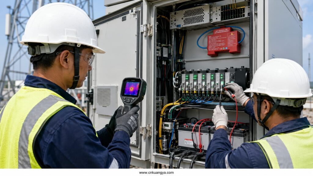
| Anualmente | Perform thermal imaging under load, inspect SPDs, test protective devices where appropriate, and review suppression-system condition |
| After a lightning event | Inspect SPD status, bonding, power supplies, and communication interfaces |
| After suppression discharge | Isolate, document, clean, investigate the root cause, replace activated devices, and recommission the complete cabinet |
Maintenance results should be stored by cabinet serial number or site ID. Trend data is more useful than isolated inspection records.
Thermal imaging is most valuable when the cabinet is operating under representative load.
A low-load inspection may miss a poor connection that becomes dangerous during peak traffic, battery charging, or high ambient temperature.
Compare similar phases, fuse holders, rectifier modules, and battery connections. A significant temperature difference between equivalent components often provides a better warning than one absolute temperature value.
Thermal imaging does not replace physical inspection. Reflective metal surfaces, airflow, emissivity, and viewing angle can distort the apparent temperature.
A discharged suppression device is evidence of an abnormal condition.
Replacing the unit without identifying the ignition source can allow the event to repeat.
The investigation should examine:
The cabinet should not automatically return to service after agent discharge.
Before purchasing a Telecom Cabinet Fire Protection package, request written answers to the following questions:
The lowest-priced component is not necessarily the lowest-cost solution.
A slightly more expensive protection system may be justified when it reduces site visits, shortens restoration time, supports remote monitoring, or prevents the loss of a critical communications node.
The following documents should be reviewed according to the project location, authority requirements, and equipment configuration:
| Estándar | Relevance |
|---|---|
| NFPA 76 | Fire protection of telecommunications facilities |
| NFPA 2010 | Fixed aerosol fire-extinguishing systems |
| ISO 15779 | Design, installation, testing, maintenance, and safety of condensed aerosol systems |
| IEC 60529 | Degrees of protection provided by enclosures using the IP Code |
| ANSI/NEMA 250 | Environmental enclosure types for electrical equipment up to 1,000 V |
| ETSI ES 203 156 | Thermal-management requirements for outdoor telecom enclosures |
| IEC 62305-4:2024 | Surge protection measures for electrical and electronic systems |
| CEI 61643-11:2025 | SPDs connected to AC low-voltage power systems |
| IEC 61643-21 | SPDs for telecommunications and signalling networks |
| IEC 61643-22 | Selection and coordination of telecom and signalling SPDs |
| IEC 62485-2 | Safety of stationary lead-acid and related battery installations |
| IEC 62485-5 | Safe operation of stationary lithium-ion batteries |
| IEC 62619:2022 | Industrial lithium-cell and battery safety requirements |
Standards establish minimum or standardized requirements. They do not replace a site-specific risk assessment.
Common initiating conditions include loose terminals, overloaded conductors, failed rectifiers, battery short circuits, damaged insulation, defective fans, severe overheating, water ingress, and surge-damaged components.
The root cause is often a combination. For example, water ingress may create corrosion, corrosion may increase resistance, and increased resistance may produce terminal overheating.
No.
IP65 indicates a defined level of protection against dust and water ingress under IEC 60529 test conditions. It does not certify resistance to internal electrical arcs, battery thermal events, condensation, overheating, smoke, or external flame exposure.
Fire protection requires separate electrical, thermal, detection, suppression, and maintenance measures.
They perform different functions.
An SPD limits transient overvoltage before it damages equipment. A suppression device responds after an ignition or defined fire condition has developed.
The SPD is preventive protection. Automatic suppression is consequence-limiting protection. Critical outdoor cabinets may require both.
The main power SPD should normally be installed close to the cable entry point or incoming distribution section.
Copper communication SPDs should also be positioned near the point where exposed cables enter the cabinet. Their earth connections should be short, direct, and bonded to the cabinet’s main earth system.
Exact positioning must follow the SPD manufacturer’s installation instructions and the project’s lightning-protection design.
Repeated failure may indicate an incorrectly selected Uc or MCOV rating, poor earthing, long connection leads, inadequate backup protection, severe local lightning exposure, neutral faults, or insufficient coordination between SPD stages.
Replacing the cartridge without investigating the system may produce another failure.
Engineers should review the supply voltage, earthing system, surge path, conductor routing, upstream protection, and event history.
It may suppress flames around electrical components or battery modules when the system has been tested and approved for the hazard.
However, aerosol should not automatically be assumed to stop thermal runaway inside a lithium cell or prevent propagation between cells.
Lithium battery protection must also include an appropriate BMS, cell monitoring, fusing, charger protection, physical separation, ventilation strategy, and emergency isolation.
Compatibility depends on the aerosol formulation, discharge temperature, residue characteristics, equipment spacing, humidity, and electronic design.
Engineers should request test reports and cleaning instructions rather than relying on a general “electronics-safe” statement.
Following a discharge, the cabinet should remain isolated until the equipment has been inspected and cleaned according to the manufacturer’s instructions.
In many enclosure designs, continuing ventilation can remove extinguishing agent and supply oxygen to the fire.
A coordinated system may stop fans, close dampers, disconnect selected loads, and then activate suppression.
The sequence must be engineered for the specific cabinet. Stopping cooling without isolating heat-producing equipment can create another hazard.
Use correct installation torque, thermal imaging under representative load, terminal temperature sensors, periodic visual inspection, and trend monitoring.
Discoloration, melted insulation, oxidized lugs, repeated fuse-holder heating, or a temperature difference between similar connections should be investigated immediately.
Remote alarms should be monitored continuously.
A practical field program commonly includes quarterly visual inspections, six-month electrical and thermal checks, and an annual detailed inspection. Severe dust, coastal corrosion, high heat, insects, or frequent storms may require shorter intervals.
Manufacturer instructions and local regulations take priority over a generic schedule.
The strongest solution is a layered package containing:
Installing only one protective component leaves several failure paths uncontrolled.
Provide the cabinet dimensions, internal compartment layout, operating voltage, incoming power type, communication interfaces, battery chemistry, maximum ambient temperature, ventilation method, earthing arrangement, required SPD ratings, and preferred suppression activation method.
Photographs, single-line diagrams, cable schedules, and expected project quantities allow a more accurate recommendation.
Telecom Cabinet Fire Protection is a system-level engineering task, not a single-product decision.
Effective Telecom Cabinet Fire Protection requires coordinated control of ignition sources, electrical fault energy, environmental exposure, battery risks, fire growth, and network interruption.
Outdoor 5G and communication cabinets face electrical faults, surge exposure, battery energy, high ambient temperature, condensation, dust, cooling failure, and external fire. Each risk needs a defined preventive or protective control.
The most reliable design combines environmental protection, thermal management, correctly coordinated fuses and circuit breakers, power and signal SPDs, battery monitoring, early detection, automatic suppression, remote alarms, and documented maintenance.
Kuangya supports cabinet manufacturers, telecom integrators, EPC contractors, and electrical engineers with coordinated SPD, fuse, and compact fire-suppression solutions for outdoor electrical enclosures.
For a project-specific recommendation, provide the cabinet layout, protected volume, voltage, battery type, communication interfaces, environmental conditions, and required technical standards.
