Zona industrial de WengYang Yueqing Wenzhou 325000
Horas de trabajo
De lunes a viernes: de 7.00 a 19.00 horas
Fin de semana: 10.00 A 17.00 HORAS
Zona industrial de WengYang Yueqing Wenzhou 325000
Horas de trabajo
De lunes a viernes: de 7.00 a 19.00 horas
Fin de semana: 10.00 A 17.00 HORAS
Last Updated: July 2, 2026 | Version 1.0
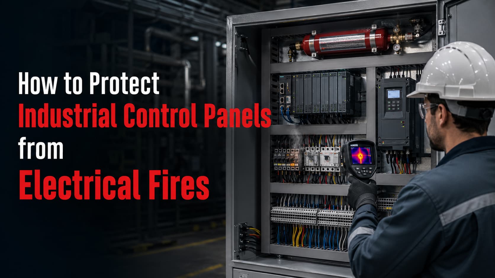
Industrial control panels are expected to operate continuously under heat, vibration, dust, switching transients and changing production loads. Inside one enclosure, power supplies, contactors, PLC modules, terminals, relays, circuit breakers and variable-frequency drives may all create different electrical and thermal stresses.
A small defect inside an electrical control cabinet can therefore develop into a serious production incident. A loose terminal may first cause only a minor temperature rise, but continued operation can damage insulation, produce arcing and ignite nearby wiring.
Efectivo Industrial Control Panel Fire Protection does not begin with a fire extinguisher. It begins with correct fault-current calculations, component coordination, enclosure design, thermal management, surge protection and preventive maintenance.
Fire suppression should then provide a final containment layer when preventive controls fail. This is why modern facilities increasingly adopt automatic fire suppression for electrical cabinets as part of a layered industrial safety strategy.This layered approach is particularly important for PLC cabinets, MCCs, VFD panels and automated production systems that cannot be safely left without protection during unmanned operating periods.
An industrial control panel is an enclosure containing electrical and electronic devices that control machinery, motors or automated processes. It may contain both low-power control circuits and high-energy power circuits.
The enclosure creates physical protection, but it also concentrates heat and combustible materials. Cable insulation, terminal blocks, plastic housings, filters and electronic circuit boards can become fuel after an electrical fault produces sufficient heat.
NFPA research estimated that US fire departments responded to an annual average of 8,077 structure fires at industrial or manufacturing properties between 2017 and 2021. These fires caused an estimated five civilian deaths, 155 injuries and USD 988 million in direct property damage per year.
Electrical distribution, lighting and power-transfer equipment was the leading equipment category involved in ignition at industrial properties. It accounted for approximately 21% of fires and 20% of direct property damage in the category shown by NFPA.
Wiring and related equipment alone accounted for 12% of industrial property fires, 13% of civilian injuries and 8% of direct property damage. This is important because wiring, terminals and connection points are also among the most common components inside industrial control cabinets.
The same report found that 39% of industrial and manufacturing structure fires occurred between 8:00 p.m. and 8:00 a.m. Those incidents produced 60% of the recorded direct property damage, showing why automatic detection and suppression are valuable during unmanned operation.
Most control-panel fires are not caused by one isolated component. They develop through a sequence of electrical, thermal and environmental failures.
| Failure mechanism | Typical source | Fire-development path |
|---|---|---|
| Loose electrical connection | Terminals, busbars, contactors or breakers | Resistance increases, the joint overheats, insulation carbonizes and arcing begins |
| Sobrecorriente | Undersized conductor, overload or stalled motor | Conductors and devices operate above their thermal limits |
| Cortocircuito | Damaged insulation, conductive contamination or wiring error | High fault current produces intense heat, metal vapor and arc energy |
| Sobretensión transitoria | Lightning, utility switching or inductive loads | Insulation and electronic components experience overstress |
| Cooling failure | Blocked filter, failed fan or high ambient temperature | Internal temperature rises and component life decreases |
| Dust and oil contamination | Cement, metal, textile, food or machining facilities | Contamination traps heat or creates conductive paths |
| Component ageing | Capacitors, relays, power supplies and contactors | Internal resistance and leakage increase over time |
| Incorrect protection coordination | Oversized breaker or wrong fuse class | Fault energy continues longer than the wiring or component can tolerate |
| Human error | Live maintenance, loose tools or incorrect testing | Conductive objects or incorrect procedures initiate an arc fault |
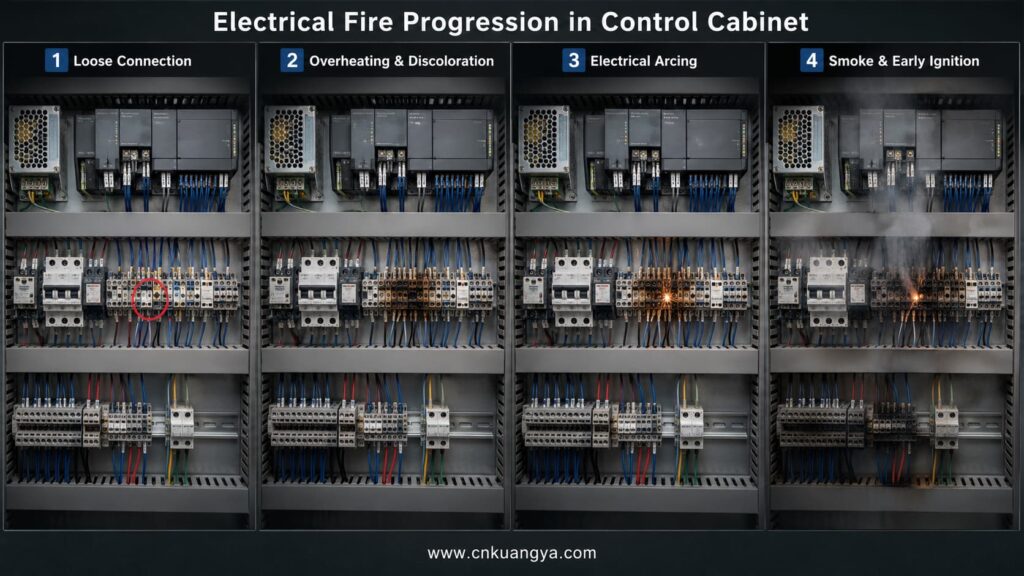
A loose connection does not always trip a circuit breaker. Current may remain below the breaker’s operating threshold while resistance at the connection generates localized heat.
The relationship can be expressed as:
Heat generated = current² × resistance × time
This means that even a moderate increase in connection resistance can produce significant heating in a heavily loaded motor feeder or MCC bus connection.
The fault may remain invisible from outside the enclosure. By the time discoloration or smoke appears, terminal insulation may already be carbonized and capable of supporting further tracking or arcing.
A fuse or circuit breaker reacts to current and time. It does not directly measure temperature at every terminal, relay or electronic component.
A poorly tightened terminal can therefore overheat without drawing enough total current to operate the upstream protective device. This is why electrical protection and condition monitoring must work together.
IEC 60269-1:2024 covers low-voltage current-limiting fuses for AC systems up to 1,000 V and DC systems up to 1,500 V. Correct fuse selection must consider voltage, current, breaking capacity, utilization category and coordination with downstream conductors and equipment.
An arc can produce heat, pressure, molten metal and conductive vapor within a very short period. The event may damage nearby cables even when the original arc is eventually interrupted.
Arcing also changes the internal environment of the cabinet. Soot and decomposed insulation can form conductive deposits, creating additional fault paths after the initial event.
Industrial Electrical Safety must therefore address both sustained fires and short-duration arc-flash events. A panel that survives an initial fault may still be unsafe to re-energize without inspection and testing.
A useful Industrial Control Panel Fire Protection strategy begins by identifying the function and energy level of the enclosure. Applying one generic design to every cabinet can leave important hazards untreated.
| Panel type | Main components | Dominant fire risks | Priority protection measures |
|---|---|---|---|
| PLC cabinet | PLC, remote I/O, 24 VDC power supply, relays, network switches | Power-supply failure, mixed-voltage wiring, terminal heating, surge damage | Circuit segregation, branch fusing, SPD, temperature monitoring |
| MCC | Busbars, motor starters, contactors, overload relays, breakers | High fault current, loose power joints, contact wear, motor overload | SCCR verification, current-limiting protection, thermography, compartmentation |
| VFD panel | Rectifier, DC-link capacitors, IGBT modules, fans, filters | Harmonic heating, capacitor ageing, blocked cooling, semiconductor failure | Ventilation, clean airflow, branch protection, surge control, thermal alarms |
| General automation cabinet | PLC, VFD, servo drive, power supplies, UPS and relays | Combined heat load, wiring congestion, multiple energy sources | Zoning, load calculation, cable management, monitoring and suppression |
| Remote or outdoor cabinet | Controls, communications, heaters and power supplies | Condensation, insects, dust, temperature cycling and lightning | Correct IP rating, anti-condensation control, SPD and sealed cable entries |
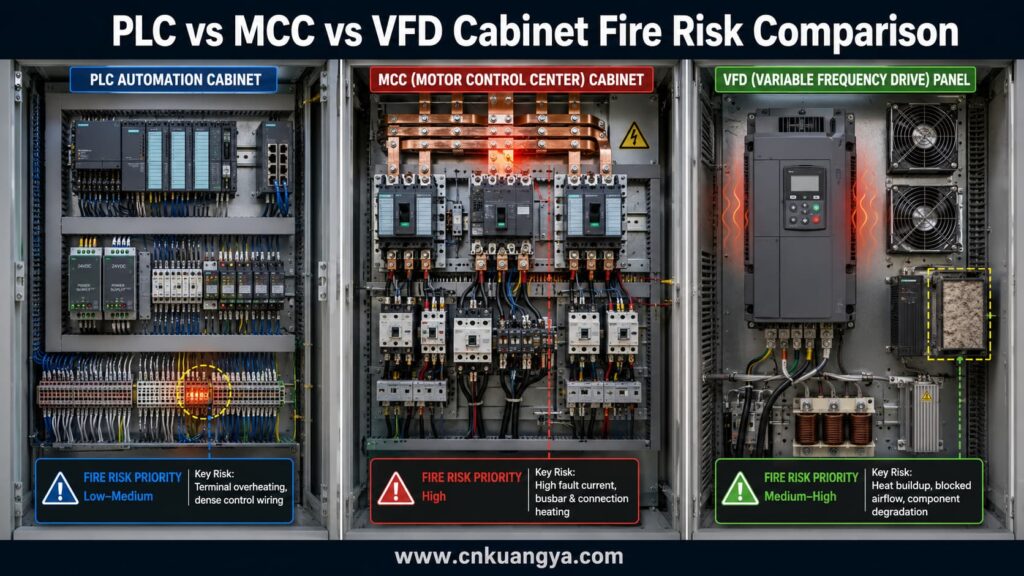
A PLC cabinet may appear low-risk because most control circuits operate at 24 VDC. However, the cabinet normally includes an AC incoming supply, one or more power supplies and numerous closely spaced conductors.
A fault in the AC side of a power supply can release far more energy than the 24 VDC output suggests. Small control wires can also overheat when incorrectly fused or connected to an unsuitable supply.
PLC Cabinet Fire Protection should begin with clear separation between mains voltage, extra-low-voltage circuits, analogue signals and communication wiring. Physical separation reduces the probability that one fault will propagate into several circuit groups.
Each power-supply output should be divided into appropriately protected branches. A single large fuse on the total 24 VDC output may not protect a small field-device conductor from overheating.
Network switches, safety PLCs and communication gateways also require attention. Failure of these devices may not start a large fire, but smoke, conductive residue or heat can disable the complete automation system.
Motor control centers contain considerably more available fault energy than typical PLC cabinets. Busbars, large conductors, motor starters and feeder breakers may carry hundreds or thousands of amperes.
MCC Cabinet Protection must therefore prioritize fault containment, short-circuit current rating and coordination of upstream and downstream protective devices.
The panel SCCR should be equal to or greater than the available fault current at the installation point, because an incorrect short-circuit current rating for industrial machinery can expose the panel to destructive fault energy. UL notes that a panel with an SCCR below the available fault current can experience extensive damage and create a dangerous condition during a short circuit.
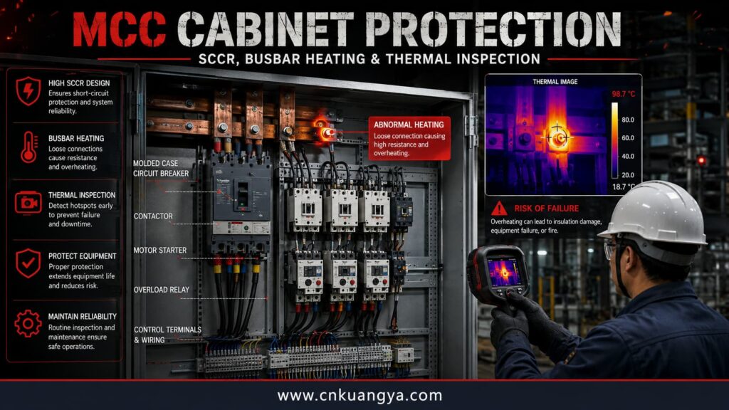
Contactors and motor starters require periodic inspection because repeated switching can wear contact surfaces. Increased contact resistance produces heat, while severe contact damage may lead to phase loss or unstable motor current.
Motor overload protection must also match the motor, duty cycle and starting method. A device that is repeatedly reset without investigating the reason for the trip can allow a mechanical or electrical problem to progress.
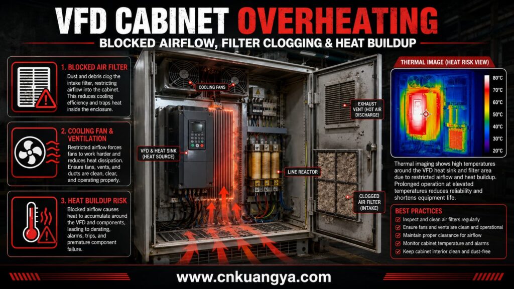
Variable-frequency drives generate heat during normal operation. Their rectifiers, DC-link capacitors, power semiconductors and braking components all contribute to the enclosure’s thermal load.
VFDs are particularly sensitive to blocked airflow. A fan failure or clogged filter can raise the internal temperature even when the drive current remains within its normal operating range.
Cooling design should use the manufacturer’s heat-loss data rather than only the VFD’s rated power. The total heat load must also include line reactors, braking resistors, transformers, power supplies and adjacent devices.
VFD cabinets may experience high-frequency electrical noise and switching transients. Good grounding, cable shielding, motor-cable routing and correct SPD coordination help reduce stress on insulation and connected controls.
DC-link capacitors have a finite service life that decreases as temperature rises. Repeated overtemperature alarms should therefore be treated as a reliability warning, not simply cleared from the drive history.
Some machines combine PLCs, servo drives, VFDs, safety relays and power distribution in one enclosure. This saves space but increases thermal interaction and wiring density.
High-power components should not be installed directly below temperature-sensitive PLC or communication modules. Rising hot air can expose these components to temperatures significantly higher than the measured room temperature.
Where practical, power electronics and control electronics should be divided into separate zones. Internal barriers or separate enclosures can reduce heat transfer and limit the spread of smoke or conductive residue.
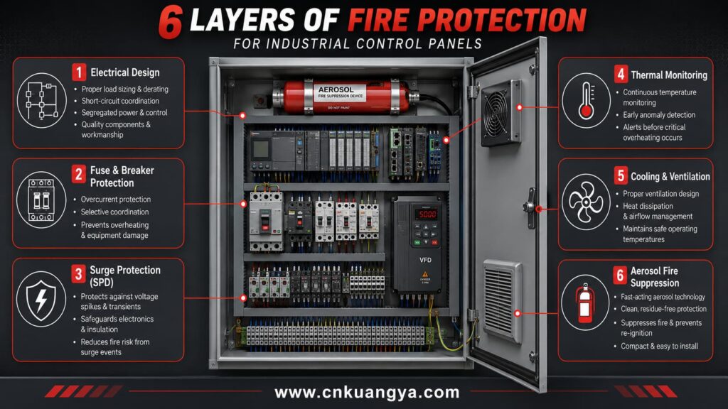
The most reliable protection strategy uses several independent layers. Each layer addresses a different stage in the development of an electrical fire.
No single device can protect against every failure. A fuse may clear a short circuit, but it will not clean a blocked VFD filter. A temperature sensor may identify overheating, but it will not limit lightning-induced voltage.
The panel design must begin with the actual supply voltage, frequency, earthing system, prospective short-circuit current, ambient temperature and load profile.
Component ratings should not be selected only from normal operating current. Starting current, regenerative loads, duty cycle, harmonic current and future expansion can change the required rating.
IEC 60204-1:2016+A1:2021 applies to electrical, electronic and programmable electronic equipment associated with machinery. It covers equipment beginning at the point where the supply connects to the machine’s electrical equipment.
IEC 61439-1:2020 establishes general definitions, construction requirements, service conditions, technical characteristics and verification requirements for low-voltage switchgear and controlgear assemblies. IEC 61439-2:2020 provides specific requirements for power switchgear and controlgear assemblies.
NFPA 79 provides safeguards for industrial machinery against electrical and fire hazards. The 2024 edition is the current published edition referenced by NFPA for industrial machinery applications.
For North American projects, UL 508A provides requirements for industrial control panels, including power circuits, control circuits, construction, components, ratings and markings. UL’s current program continues to use the third edition of UL 508A.
Overcurrent protection should isolate the smallest practical faulted section without unnecessarily shutting down the complete production line.
Main, feeder and branch protection must be coordinated. The upstream device must have sufficient breaking capacity, while downstream devices should protect the conductor and connected equipment.
Current-limiting fuses can reduce peak current and let-through energy during short-circuit events. This can improve equipment protection when the fuse is correctly coordinated with the available fault current and downstream component ratings.
However, a fuse with an excessive ampere rating may allow small conductors or electronic devices to overheat. Selecting a fuse only to avoid nuisance operation is not an acceptable engineering method.
| Protection level | Main purpose | Typical device |
|---|---|---|
| Incoming supply | Isolate the complete panel and interrupt major faults | MCCB, switch-fuse or disconnect |
| Motor feeder | Protect feeder conductors and motor branch circuit | Fuse, MCCB or motor-protection breaker |
| Control transformer | Protect transformer primary and secondary circuits | Time-delay or application-specific fuse |
| 24 VDC branch | Protect small field wiring and individual loads | Electronic circuit protector or DC fuse |
| Semiconductor circuit | Limit energy reaching power electronics | High-speed semiconductor fuse |
| Auxiliary circuit | Protect fans, heaters, lights and sockets | MCB or fuse |
Protection-device voltage ratings must match the circuit. AC-only breakers or fuses must not be assumed suitable for DC circuits, because DC interruption requires different arc-control performance.
For low-voltage AC control panels, a correctly selected Type 2 AC surge protective device can help limit transient overvoltage reaching PLC power supplies, VFD control circuits and industrial communication equipment.
SPDs are designed to limit transient overvoltage and divert surge current. They do not protect against sustained overload or short-circuit current.
IEC 61643-01:2024 contains common requirements for SPDs connected to systems rated up to 1,000 V AC or 1,500 V DC. CEI 61643-11:2025 covers SPDs connected to AC low-voltage power systems.
An industrial panel can receive transients from the utility supply, nearby lightning, large motor switching, contactor coils, solenoids and inductive loads. Sensitive PLC inputs and communication devices may be damaged even when no visible fire occurs.
A coordinated SPD arrangement should normally be considered at the building distribution level and at sensitive downstream panels. The final selection depends on system voltage, earthing arrangement, expected surge environment and upstream protection.
The connecting conductors should be short and direct. Excessive conductor length adds inductive voltage during a fast surge and can reduce the effective protection level at the equipment.
Signal and communication lines may require separate surge protection. Installing an SPD only on the AC incoming supply does not protect fieldbus, Ethernet, analogue or remote-I/O conductors entering from outside the cabinet.
Conductors should be sized for actual load, ambient temperature, grouping, installation method and terminal limitations.
Terminals must be tightened using the specified tool and torque. “Tight by hand” is not a measurable acceptance criterion.
Stranded conductors should use appropriate ferrules or terminals where required. Stray strands can reduce creepage distances or contact adjacent conductive parts.
Repeated retightening without diagnosis should be avoided. If a connection repeatedly loosens, engineers should investigate vibration, conductor preparation, terminal condition, thermal cycling and mechanical support.
Power wiring should not be tightly bundled around heat-producing components. Adequate bending radius and cable support reduce mechanical stress at terminals.
The cabinet’s internal temperature should be calculated under the worst credible operating condition. This includes maximum ambient temperature, full production load and expected contamination of filters.
Passive ventilation may be sufficient for small PLC cabinets, but VFD and servo panels often require forced ventilation, air conditioning or heat exchangers.
Airflow should move heat away from sensitive components rather than recirculating it. Inlet and outlet locations must also avoid drawing contaminated air directly across power electronics.
Filters require a defined maintenance interval. A fan does not provide reliable cooling when its inlet is blocked by dust, oil mist or textile fibers.
Enclosure heaters may be required in outdoor or intermittently operating cabinets. Their purpose is to prevent condensation, but incorrectly positioned heaters can overheat nearby wiring.
High-energy power circuits should be separated from PLC, instrumentation and communication circuits.
The separation can include physical distance, wiring ducts, barriers or separate cabinet sections. The appropriate method depends on voltage, fault level and functional requirements.
Braking resistors, line reactors and transformers should have sufficient clearance from plastic ducts and cable insulation. They should not be treated as ordinary low-temperature control components.
Batteries and small UPS units introduce additional failure modes. Battery chemistry, charging method, ventilation and replacement intervals should be included in the fire-risk assessment.
Unused cable-entry openings should be closed. Openings allow dust, insects, metal particles and moisture to enter while also reducing the effectiveness of enclosure fire suppression.
The enclosure rating must match the environment. A cabinet in a clean indoor electrical room has different requirements from a panel exposed to washdown, cement dust, corrosive vapor or outdoor condensation.
A higher IP rating is not automatically better if heat cannot escape. Engineers must balance environmental sealing with thermal performance.
Cable insulation, terminal blocks and wiring ducts should have suitable temperature and flame-performance ratings. Components should also be installed within the conditions covered by their certification.
IEC 60364-4-42:2024 addresses protection of persons, property and equipment against thermal effects, combustion, material degradation and the spread of fire from electrical installations.
Preventive maintenance is a central part of Industrial Control Panel Fire Protection because many cabinet failures develop gradually.
A maintenance program should be based on equipment condition, operating environment, fault consequences and manufacturer instructions. One fixed interval is not appropriate for every panel.
NFPA 70B provides requirements for establishing and carrying out electrical equipment maintenance programs. It applies to electrical, electronic and communication equipment used in facilities including industrial plants.
| Inspection method | What it can reveal | Important limitation |
|---|---|---|
| Inspección visual | Discoloration, dust, damaged insulation, loose parts | Cannot identify every internal hot spot |
| Infrared thermography | Abnormal terminal, breaker, fuse or contactor temperature | Load must be sufficient for meaningful comparison |
| Current measurement | Overload, phase imbalance and abnormal motor conditions | Does not directly locate every high-resistance connection |
| Torque verification | Loose terminals and assembly defects | Must follow manufacturer instructions |
| Insulation testing | Degraded insulation and contamination | Sensitive electronics may require disconnection |
| Power-quality monitoring | Harmonics, sags, swells and transients | Requires correct instrument setup and interpretation |
| Event-log analysis | VFD overtemperature, phase loss and repeated faults | Logs may be cleared or lack sufficient context |
| Fan and filter inspection | Reduced airflow and cooling failure | Condition can change rapidly in dusty environments |
| Functional trip testing | Failure of protective or monitoring devices | Must be planned to avoid process hazards |
A hot component is not automatically defective. The engineer should compare similar phases, similar components and previous measurements under comparable load.
A temperature difference between phases may indicate unequal loading, contact resistance or an internal component problem.
Absolute temperature also matters. A small temperature difference can still be dangerous when the complete enclosure is already operating near the maximum permitted temperature.
Thermal images should be retained with load current, ambient temperature, inspection date and equipment identification. Without this information, trend analysis becomes unreliable.
Repeated VFD overtemperature, power-supply undervoltage or communication-loss alarms may indicate a developing cabinet problem.
Resetting an alarm restores production but does not remove the cause. Maintenance teams should record the frequency, operating condition and affected equipment.
A pattern of short, intermittent alarms can be more valuable than a single shutdown event. It may reveal airflow restriction, transient voltage or a connection that changes resistance during thermal cycling.
OSHA recorded a 2012 incident at Gerdau Ameristeel in which a meter rated for a maximum of 1,000 V was applied to an energized 4,160 V circuit. Lockout identification and equipment interpretation errors contributed to an arc flash that hospitalized three workers.
In a separate 2020 case, a technician dropped a screw inside an electrical panel. Movement of the panel caused the screw to fall again and create an arc flash, resulting in second-degree burns to both hands and arms.
OSHA also documented a 2019 incident in which an electrician was connecting an air conditioner to a 440 V supply inside an electrical box. Multiple arc flashes occurred and caused burns requiring hospitalization.
These cases were primarily arc-flash incidents rather than examples of long-duration cabinet fires. However, they demonstrate that incorrect voltage identification, live work and small conductive objects can release enough energy to ignite clothing, insulation or nearby materials.
Wherever possible, a panel should be placed in an electrically safe work condition before it is opened or modified.
Isolation must include every relevant energy source. Backfeeds, control transformers, UPS systems, DC buses, capacitors and externally supplied control circuits can remain energized after the main disconnect is opened.
NFPA 70E addresses electrical safety-related work practices, risk assessment, energized work and personal protective equipment. The 2024 edition was issued in 2023 and remained the current published edition during preparation of this article.
PPE reduces injury severity but does not make unnecessary energized work safe. The first objective should remain hazard elimination through correct isolation and verification.
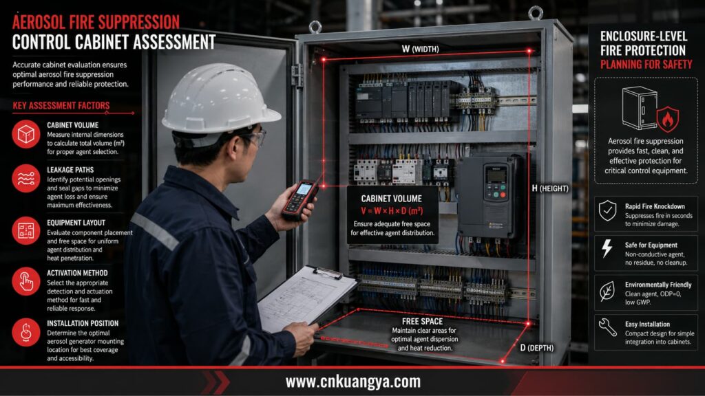
Engineers evaluating enclosure-level suppression should first determine the cabinet volume, leakage conditions, operating temperature and activation method. Our aerosol fire extinguisher selection guide explains these factors in greater detail.
Aerosol fire suppression is a final protection layer designed to control a developing fire inside a defined enclosure.
It is not a substitute for correct wiring, fault protection, thermal management or maintenance. A cabinet with repeated overheating should be repaired before suppression is added.
Additional application examples for switchgear, control panels and enclosed power equipment are covered in our guide to aerosol fire extinguishers for electrical cabinets.
A condensed aerosol generator normally contains a solid aerosol-forming compound. When activated, the compound produces fine particles and gaseous products that interfere with the chemical reactions sustaining combustion.
The agent can be stored without a conventional high-pressure cylinder. This allows compact units to be installed inside electrical cabinets where space is limited.
The effectiveness of the system depends on the protected volume, fire class, enclosure leakage, unit location and required extinguishing concentration.
ISO 15779:2011 specifies requirements and test methods for condensed aerosol system components and gives recommendations for design, installation, testing, maintenance and safety. At the time of writing, ISO was developing a replacement edition.
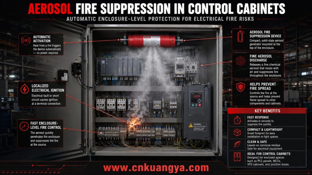
Aerosol Fire Suppression may be considered for:
The enclosure must be sufficiently defined for the agent to reach an effective concentration. Large open-bottom cabinets or panels connected to extensive unsealed cable ducts may not retain the agent.
| Método | Main advantage | Main limitation | Aplicación típica |
|---|---|---|---|
| Condensed aerosol | Compact, automatic and suitable for small enclosures | Residue and equipment compatibility require evaluation | PLC, MCC, VFD and remote cabinets |
| Clean-agent gas | Low residue and suitable for valuable electronics | Cylinders, piping and pressure-relief design may be required | Electrical rooms and larger enclosures |
| CO₂ | Effective and widely understood | Serious personnel-safety restrictions in occupied spaces | Controlled industrial applications |
| Water mist | Strong cooling and limited water demand | Electrical approval and drainage must be evaluated | Machinery spaces and larger equipment |
| Portable extinguisher | Flexible manual response | Depends on personnel presence and safe access | Backup response only |
| Detection and shutdown only | Can remove electrical energy early | Does not extinguish burning insulation after power removal | Systems with reliable supervision |
The most suitable technology depends on enclosure volume, equipment sensitivity, maintenance capability and project cost. See the detailed comparison of thermal aerosol and traditional fire suppression systems before selecting an enclosure-level solution.
An aerosol device should not be selected only by its external dimensions or agent mass.
The first input is the net protected volume. Engineers should deduct major solid components only when the system design method permits it and should account for interconnected compartments.
The required agent quantity depends on the manufacturer’s tested application density or design concentration. Different compounds and unit designs cannot be compared only by saying that both contain “30 g” or “100 g.”
For small distribution and control enclosures, the selection process should include protected volume, installation position and discharge clearance. The 30g cabinet automatic fire extinguishing device engineering guide provides a more detailed sizing and installation reference.
A correct specification should identify:
Thermal activation is simple and can operate without an external control panel. It is useful where the enclosure must retain independent fire protection after loss of auxiliary power.
Electrical activation can be connected to smoke, heat or multi-criteria detection. This allows alarms, machine shutdown and remote status signals to be coordinated.
Dual activation may provide both an electrically controlled response and an independent thermal backup. The arrangement must prevent accidental discharge during normal cabinet temperature peaks.
The activation temperature should remain above the highest credible operating temperature but low enough to respond before fire growth becomes severe.
The unit should be installed where discharge will not be blocked by large components or wiring ducts.
Direct exposure of sensitive devices to the hottest discharge region should be avoided. Minimum clearances stated by the manufacturer must be respected.
The mounting surface should withstand the mechanical and thermal effects of activation. Adhesive-only mounting should be evaluated carefully in high-temperature, oily or high-vibration environments.
The device must not obstruct maintenance access, ventilation paths, door operation or the safe movement of wiring.
Where process safety permits, the suppression system should initiate electrical isolation before or at the time of discharge.
Removing power reduces continued arc energy and the risk of re-ignition. However, emergency shutdown must not create a more serious mechanical, chemical or process hazard.
Critical systems may require selective isolation rather than total shutdown. For example, safety PLCs, emergency ventilation or fire-alarm communication may need an independent protected supply.
The cause-and-effect matrix should define detection, alarms, machine stop, isolation, ventilation control and remote notification.
Condensed aerosol systems produce particles. The effect of those particles on electronics depends on formulation, concentration, humidity, equipment construction and exposure time.
Claims such as “no damage to electronics” should therefore be supported by application-specific testing rather than assumed for every product.
After discharge, the cabinet should remain isolated until qualified personnel have inspected it. Cleaning, insulation testing and replacement of damaged devices may be required before re-energization.
Suppression can prevent fire spread, but it does not restore the failed terminal, contactor, conductor or power supply that caused the incident.
Industrial Control Panel Fire Protection should be documented as part of the electrical design and maintenance system.
The applicable standard depends on the country, machine type, voltage, installation and authority having jurisdiction. A project may need to satisfy several standards at the same time.
| Estándar | Main relevance |
|---|---|
| IEC 60204-1:2016+A1:2021 | Electrical equipment and systems associated with machinery |
| IEC 61439-1:2020 | General rules for low-voltage switchgear and controlgear assemblies |
| IEC 61439-2:2020 | Power switchgear and controlgear assemblies |
| IEC 60364-4-42:2024 | Protection against thermal effects and fire propagation |
| IEC 60364-4-43:2023 | Protection of conductors against overcurrent |
| IEC 60269-1:2024 | General requirements for low-voltage fuses |
| IEC 61643-01:2024 | Common requirements for low-voltage SPDs |
| CEI 61643-11:2025 | SPDs connected to AC low-voltage power systems |
| NFPA 79:2024 | Electrical safety requirements for industrial machinery |
| NFPA 70B:2023 | Electrical equipment maintenance programs |
| NFPA 70E:2024 | Safe electrical work practices and arc-flash risk |
| UL 508A, Third Edition | Construction and certification of industrial control panels |
| ISO 15779:2011 | Condensed aerosol fire-extinguishing system requirements |
IEC 60364-4-43:2023 specifically addresses protection of conductors against harmful effects caused by overcurrent and coordination of overcurrent protective measures.
These standards should be treated as a technical framework rather than a substitute for project-specific calculations. Local codes and authority requirements take precedence where applicable.
| No. | Protection measure | Required engineering action |
|---|---|---|
| 1 | Calculate available fault current | Confirm that panel SCCR and device breaking capacity are sufficient |
| 2 | Coordinate fuses and breakers | Protect each conductor and load while limiting fault energy |
| 3 | Install coordinated SPDs | Protect incoming power and exposed signal circuits |
| 4 | Control terminal quality | Use correct preparation, torque and inspection procedures |
| 5 | Calculate enclosure temperature | Include every heat-producing component and worst-case ambient |
| 6 | Separate power and control circuits | Reduce thermal interaction and fault propagation |
| 7 | Implement condition monitoring | Use thermography, alarms, current data and maintenance records |
| 8 | Provide automatic suppression where justified | Engineer agent quantity, activation and interlocks for the enclosure |
| 9 | Test and document the complete system | Retain calculations, schematics, settings, inspection records and changes |
A buyer should not request only “one fire extinguisher for an electrical cabinet.” That description does not provide enough information for safe selection.
A more useful enquiry should include the cabinet type, dimensions, internal equipment, voltage, ambient temperature, ventilation arrangement and desired activation method.
For SPD selection, the supplier should receive the nominal voltage, system configuration, earthing arrangement, installation location and required surge rating.
For fuse selection, the supplier needs normal current, conductor size, load type, starting current, operating voltage and available fault current.
For aerosol suppression, the supplier should also receive photographs or layout drawings showing ventilation openings and possible discharge obstructions.
| Pregunta | Por qué es importante |
|---|---|
| Which standard is the device tested against? | Confirms whether claims are supported by defined tests |
| What protected volume is covered? | Determines whether the device is correctly sized |
| What are the installation clearances? | Prevents thermal or mechanical damage during discharge |
| How is the unit activated? | Affects response time, wiring and system independence |
| Can it provide alarm or shutdown outputs? | Enables integration with PLC and safety systems |
| What maintenance is required? | Establishes lifecycle cost and inspection duties |
| ¿Cuál es la vida útil? | Prevents expired units remaining in critical cabinets |
| What post-discharge cleaning is required? | Supports safe recovery of electrical equipment |
| Is the product suitable for the ambient temperature? | Prevents false activation or reduced performance |
| Are application drawings available? | Reduces installation errors |
Kuangya’s engineering approach combines preventive electrical protection with enclosure-level fire containment.
The first layer uses correctly selected fuses or circuit breakers to interrupt overload and short-circuit current.
The second layer uses SPDs to reduce transient-voltage stress on PLC power supplies, drives, communication devices and other sensitive equipment.
The third layer uses compact aerosol fire-suppression devices where an enclosure-specific risk assessment shows that automatic fire control is required.
For project selection, the customer should provide the electrical diagram, cabinet dimensions, voltage, load information and application environment. This allows the components to be selected as one coordinated system rather than as unrelated products.
The final design must still be reviewed by the project engineer and approved under the applicable local code, certification scheme and authority requirements.
Yes. A PLC cabinet usually contains an AC incoming supply, AC/DC power supplies, relays and numerous small conductors. An internal power-supply fault, loose AC connection or incorrectly protected 24 VDC branch can generate enough heat to damage insulation and start a fire.
No. PLC cabinets mainly require protection for sensitive electronics, small conductors, power supplies and mixed-voltage wiring. MCCs contain higher fault currents, busbars, contactors and motor feeders, so SCCR, fault containment and current-limiting protection have greater importance.
No. A fuse protects against defined overcurrent conditions. It may not operate during localized resistance heating at a loose terminal because the total circuit current can remain below the fuse rating. Maintenance, temperature monitoring and correct assembly are still required.
The SPD should normally be coordinated with protection at the upstream distribution board and installed close to the panel’s incoming supply. Connections should be short and direct. Exposed communication, analogue and field-signal lines may require separate signal SPDs.
Common causes include blocked filters, failed fans, excessive ambient temperature, incorrect enclosure sizing, harmonic current, high switching frequency and insufficient clearance. Heat from braking resistors, reactors and transformers must also be included in the calculation.
It can be suitable when the product and application have been properly evaluated. Engineers must verify agent concentration, discharge temperature, residue, dielectric compatibility and post-discharge cleaning requirements. Compatibility should not be assumed from the word “aerosol” alone.
Agent quantity cannot be selected from cabinet height alone. It depends on net protected volume, enclosure leakage, fire risk, tested application density and manufacturer instructions. Two units with the same agent mass may not provide identical protection.
Generally, electrical isolation helps reduce arc energy and re-ignition risk. However, shutdown logic must be reviewed against process safety requirements. Safety controls, emergency ventilation or communication systems may require selective rather than complete isolation.
The interval should be risk-based. High-load MCCs, dusty VFD panels and critical continuous-process cabinets normally require more frequent attention than lightly loaded cabinets in clean rooms. Inspection frequency should consider operating environment, fault history and manufacturer guidance.
No. Suppression controls the consequences of a fire but does not repair loose terminals, overloaded conductors, failed fans or aged components. Preventive maintenance remains the primary method for reducing ignition probability.
Efectivo Industrial Control Panel Fire Protection requires more than installing one protective device.
Engineers must control the complete failure chain: transient overvoltage, overcurrent, terminal heating, cooling failure, insulation damage, arcing, ignition and fire spread.
PLC cabinets require careful branch protection and separation of sensitive control circuits. MCCs require strong fault-current coordination and attention to power connections. VFD panels require disciplined thermal management and monitoring of cooling performance.
SPDs, fuses, circuit breakers, temperature monitoring and preventive maintenance form the primary protection layers. Aerosol fire suppression can then provide rapid enclosure-level containment when a residual fire risk remains.
Kuangya supplies electrical protection components and compact aerosol fire-suppression solutions for PLC cabinets, MCCs, VFD panels and industrial automation projects. Project selection should be based on electrical parameters, cabinet volume, equipment layout and operating environment rather than a generic one-device specification.
