WengYang Industriegebiet Yueqing Wenzhou 325000
Arbeitszeiten
Montag bis Freitag: 7AM - 7PM
Am Wochenende: 10AM - 5PM
WengYang Industriegebiet Yueqing Wenzhou 325000
Arbeitszeiten
Montag bis Freitag: 7AM - 7PM
Am Wochenende: 10AM - 5PM
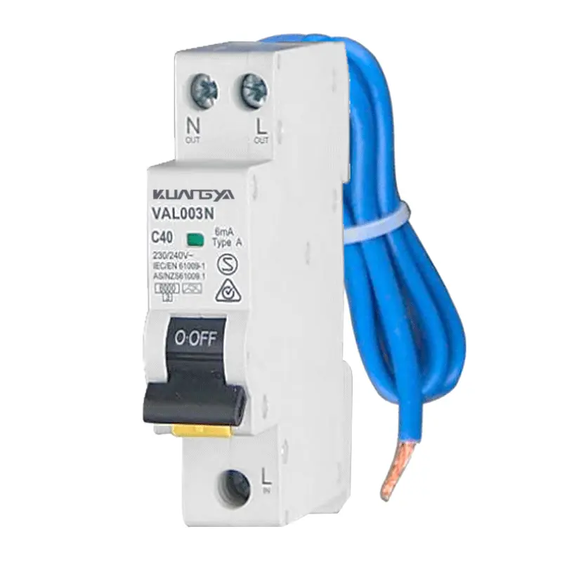
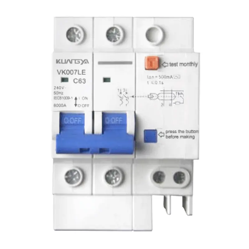
Eine RCBO (Fehlerstromschutzschalter mit Überstrom) integriert Fehlerstromschutz und Überstromschutz in einem kompakten, modularen Gerät.
In einer Einheit wird ein RCBO-Unterbrecher bietet sowohl Leckageschutz (wie ein RCCB) und Überlast-/Kurzschlussschutz (wie ein MCB). Durch diese Doppelfunktion entfällt die Notwendigkeit, einen separaten Fehlerstrom-Schutzschalter mit einem Leitungsschutzschalter für Klemmenstromkreise zu verbinden, was Platz auf der DIN-Schiene spart und die Verdrahtung vereinfacht. Da ein RCBO-Schutzschalter löst aus, wenn entweder der Fehlerstrom seine Empfindlichkeit überschreitet (z. B., RCBO 30mA) oder ein Überstrom erkannt wird, wird sie in großem Umfang in Wohn- und Geschäftsgebäuden und zunehmend auch in Leichtindustrieanlagen eingesetzt.
Verglichen mit rcbo vs mcb: Ein MCB allein kann keinen Erdschluss erkennen. Verglichen mit rcbo vs rccb: Ein Fehlerstromschutzschalter allein kann nicht gegen Überlast oder Kurzschluss schützen. Der Fehlerstromschutzschalter vereint die beiden Schutzlogiken, wodurch sich der Koordinierungsaufwand verringert und die Selektivität der Endstromkreise erhöht. Konstrukteure wählen in der Regel RCBO einpolig (1P+N) für einphasige Lasten, 2-polig RCBO für spezifische Isolationsbedürfnisse, und 3-Phasen-RCBO (3P oder 3P+N / 4P) für die dreiphasige Verteilung und Maschinen.
Das RCBO-Portfolio von Kuangya umfasst mehrere Auslösekurven (B/C/D) zur Anpassung an die Einschaltcharakteristik, Nennströme für gängige Stromkreisgrößen und Empfindlichkeitsoptionen, die auf den Personenschutz (30 mA) und die vorgelagerte Diskriminierung (100/300 mA) zugeschnitten sind. Die nachstehende Auswahlhilfe hilft Ihnen bei der Wahl der richtigen Polkonfiguration, Kennlinie und Empfindlichkeit für typische Anwendungen wie RCBO für EV-Ladung und RCBO für PV-Anlage Schnittstellen.
Kompakte Sicherheit: Fehlerstrom- und Überstromschutz, entwickelt für die moderne AC-Verteilung.
RCBO kombiniert Erdschlusserkennung und thermisch-magnetischen Überstromschutz und vereinfacht so die Konstruktion des Endstromkreisschutzes.
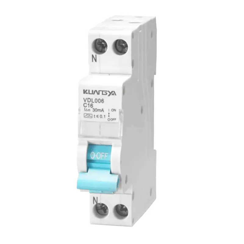
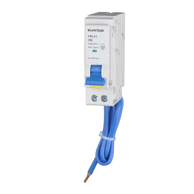
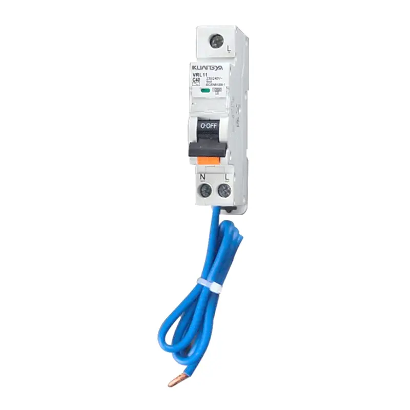
Wählen Sie RCBO einpolig (1P+N), 2-polig RCBO, oder 3-Phasen-RCBO (3P / 3P+N / 4P), um die Systemtopologie und die Isolationsanforderungen zu erfüllen.
Allgemein RCBO 30mA für den Personenschutz; 100/300-mA-Varianten für die vorgeschaltete Selektivität und die Minderung des Brandrisikos.
Lasteinschaltdauer anpassen: Kurve B für Beleuchtungs-/Steckdosenlasten, C für allgemeine Motorlasten, D für Geräte mit hoher Einschaltdauer.
Die Verfügbarkeit des Typs AC/A/F/B (serienabhängig) unterstützt Geräte mit Leistungselektronik, Antrieben und EV/PV-Schnittstellen.
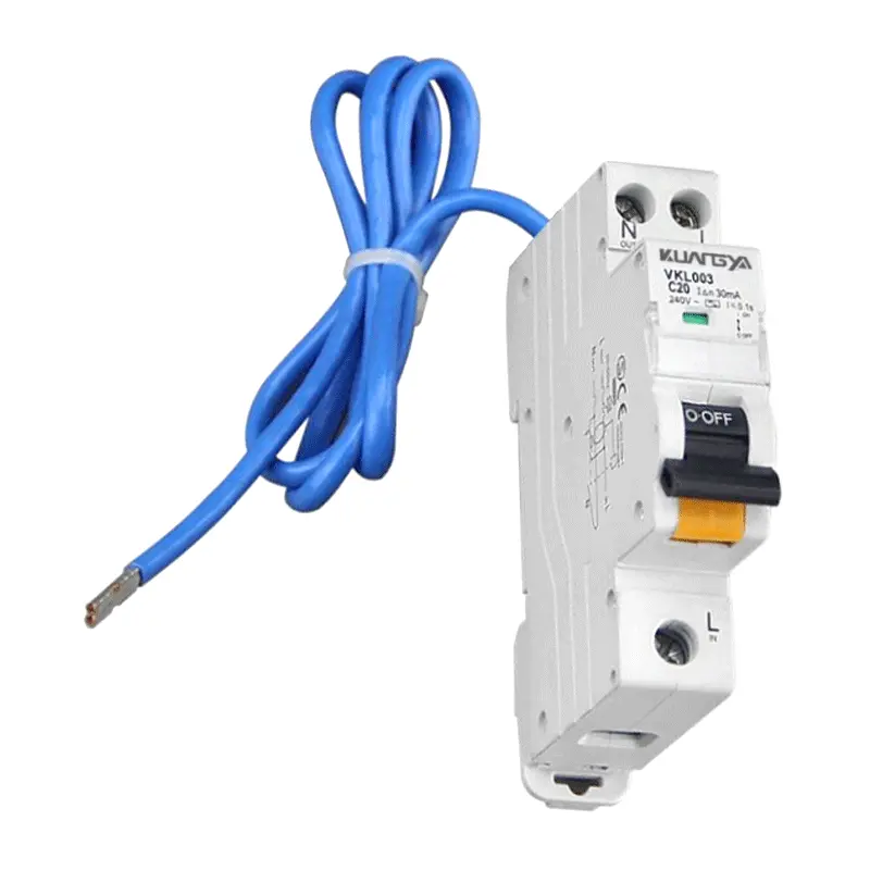
35 mm EN 60715-Schienenmontage, kompakte Breiten und mit Stift-/Gabelschienen kompatible Klemmen für eine schnelle Montage.
Das Statusfenster und die TEST-Taste ermöglichen eine schnelle Überprüfung vor Ort; es wird eine monatliche Prüfung gemäß den örtlichen Vorschriften empfohlen.
Entwickelt nach IEC/EN 61009-1 (serienabhängige Zulassungen wie CE/CB/UKCA/RoHS sind je nach Familie erhältlich).
Von Privathäusern bis hin zu gewerblichen Gebäuden und der Leichtindustrie - RCBOs erhöhen die Basissicherheit bei minimalem Platzbedarf.
Schützen Sie Steckdosen- und Beleuchtungskreise mit RCBO 30mA zum Schutz der Menschen. RCBO einpolig (1P+N) ist bei einphasigen Stromkreisen üblich und erleichtert die Fehlersuche und Isolierung.
In Büros und im Einzelhandel profitieren gemischte Lasten (LED-Treiber, IT-Geräte) von Geräten des Typs A/F, die pulsierende Gleichstrom-/Hochfrequenzkomponenten ohne störende Auslösungen handhaben.
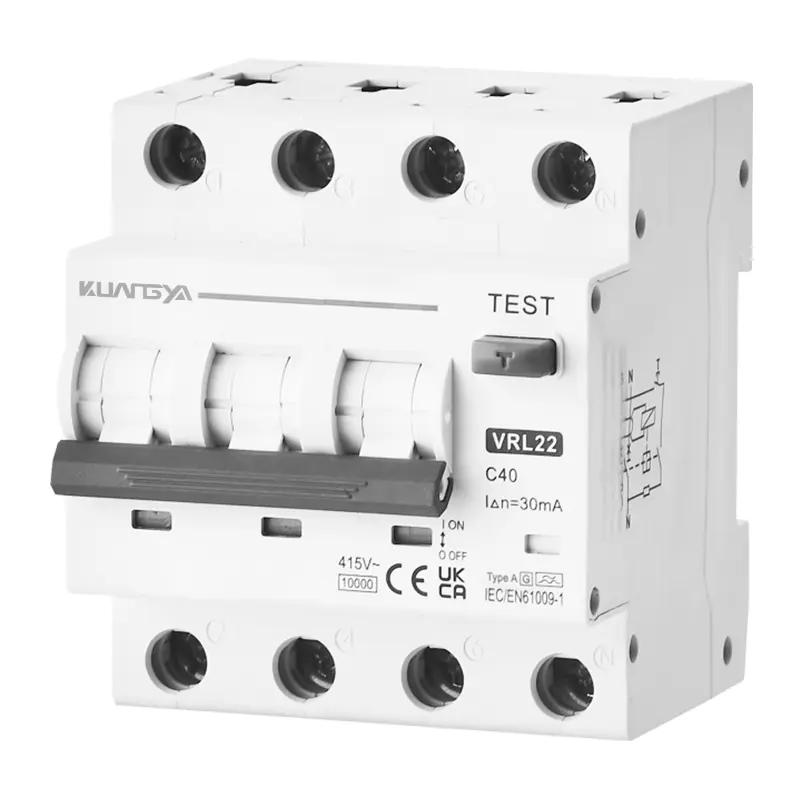
Verwenden Sie 3-Phasen-RCBO mit geeigneter Kennlinie (C/D) und Empfindlichkeit für kleine Motoren, Förderanlagen und HLK-Geräte unter Beibehaltung des Fehlerstromschutzes.
EVSE kann DC-Restkomponenten erzeugen. Bestätigen Sie Typ A + DC-Überwachung oder Typ B gemäß den Spezifikationen des Ladegeräts; koordinieren Sie sich im Vorfeld mit AFDD und AC SPD wenn es die Risikobewertung vor Ort erfordert.
PV-Wechselrichter können komplexe Leckagesignaturen verursachen. Verwenden Sie den vom Hersteller des Wechselrichters angegebenen Typ A/F/B und achten Sie auf eine selektive Koordination mit vorgeschalteten Geräten.
Wo ein kontinuierlicher Betrieb wichtig ist, minimieren RCBOs pro Stromkreis kollaterale Ausfälle - nur die betroffenen Abzweige werden ausgelöst, was die Selektivität im Vergleich zu gemeinsamen RCCB+MCB-Schemata verbessert.
Wählen Sie für jeden Stromkreis Polkonfiguration, Wellenformtyp, Auslösekurve, Nennstrom und Empfindlichkeit.
| Parameter | Option | Typische Verwendung |
|---|---|---|
| Pole | 1P+N / 2P / 3P / 3P+N / 4P | Einphasige gegenüber dreiphasigen Stromkreisen; Isolationsbedarf; Anforderungen an den Neutralleiterwechsel. |
| Wellenform Typ | AC / A / F / B | Reiner Wechselstrom; Wechselstrom + pulsierender Gleichstrom; HF-reiche Wandler; glatter Gleichstrom (EV/PV). |
| Reisekurve | B / C / D | B: Beleuchtung/Widerstand; C: gemischt und Motor; D: Maschinen mit hohem Stromfluss. |
| Empfindlichkeit (IΔn) | 30 / 100 / 300 mA | 30 mA für den Personenschutz; 100/300 mA für die vorgelagerte Selektivität/Brandminderung. |
| Nennstrom | Je nach Kabel und Last | Passen Sie den Auslegungsstrom an; überprüfen Sie die Umgebung, die Gruppierung und die Leistungsschalterreduzierung. |
Halten Sie sich an die gute Praxis: korrekte Polarität, Leiterdimensionierung, Drehmoment und regelmäßige Prüfung.
Leitung und Nullleiter müssen durch den RCBO-Fühlerkern geführt werden. RCBO einpolig (1P+N) vereinfacht die Isolierung und Fehlerdiagnose in jedem Endstromkreis.
2-polig RCBO bietet in bestimmten Systemen eine vollständige Abschaltung; 3-Phasen-RCBO (3P/3P+N/4P) schützt dreiphasige Lasten mit entsprechender Kennlinie und Empfindlichkeit.
Beachten Sie die Drehmomentangaben des Herstellers; verwenden Sie kompatible Stift/Gabel-Sammelschienen; verlegen Sie die Neutralleiter korrekt; führen Sie einen monatlichen Test über die TEST-Taste gemäß den örtlichen Vorschriften durch.
| Szenario | Empfohlene RCBO | Anmerkungen |
|---|---|---|
| Steckdosen/Beleuchtung für Wohngebäude | 1P+N, Typ A, 30 mA, Kurve B/C | Geringer Einschaltstrom; Priorität haben Personenschutz und Störfestigkeit. |
| Büro-IT-Schaltungen | 1P+N, Typ A/F, 30 mA, Kurve C | Schaltnetzteile → Typ A/F für pulsierende DC/HF-Toleranz wählen. |
| Kleinmotoren/HVAC | 3P oder 3P+N, Typ A/F, 30-100 mA, Kurve C/D | Berücksichtigen Sie den Einschaltstrom des Motors; überprüfen Sie die Leckagemuster der Antriebe. |
| EV-Ladegerät-Branche | Gemäß EVSE-Spezifikation: Typ A + DC-Monitor oder Typ B | Rücksprache mit dem Hersteller; hinzufügen AC SPD und berücksichtigen AFDD zum Risiko. |
| PV-Wechselrichter-Schnittstelle | Gemäß Wechselrichter-Spezifikation: Typ A/F/B | Handbuch befolgen; Diskriminierung durch vorgelagerten Schutz sicherstellen. |
Typische Hüllkurvenwerte für die Kuangya RCBO-Serie. Überprüfen Sie die endgültigen Zahlen auf dem spezifischen Datenblatt für die gewählte Familie.
| Parameter | Typischer Wert / Bereich |
|---|---|
| Normen und Einhaltung | IEC/EN 61009-1 (Fehlerstrom-Schutzschalter mit integriertem Überstromschutz) |
| Masten-Optionen | 1P+N (RCBO einpolig), 2P (2-polig RCBO), 3P, 3P+N / 4P (3-Phasen-RCBO) |
| Wellenform-Typen | Typ AC / A / F / B (serienabhängig; je nach Anwendung wie EV/PV bestätigen) |
| Reisekurven | B / C / D (thermisch-magnetische Eigenschaften für Einschaltanpassung) |
| Nennstrom (In) | Gemeinsame Nennwerte, die auf Leitergrößen und Lasten abgestimmt sind (z. B. 6-63 A; höhere Nennwerte serienabhängig) |
| Restliche Empfindlichkeit (IΔn) | RCBO 30mA für den Personenschutz; 100 / 300 mA für die vorgeschaltete Selektivität und Brandbekämpfung (wo zulässig) |
| Nenn-Betriebsspannung (Ue) | 1P+N/2P: 230-240 V~; 3P/3P+N/4P: 400-415 V~ |
| Isolierung/Impuls | Ui ≥ 500 V; Uimp 4-6 kV (serienabhängig) |
| Ausschaltvermögen (Icn/Ics) | Thermisch-magnetische Überstromunterbrechung im Bereich von 6-10 kA (Icn), Leistungsvermögen Ics pro Serie |
| Bedingter Kurzschluss | Mit vorgelagerter Gerätekoordinierung, falls erforderlich; siehe Tabelle der Baureihen für Inc/IΔc |
| Ausdauer | Mechanisch/Elektrisch ≥ 10.000 Schaltspiele (typisch) |
| Anschlussklemmen & Drehmomente | Großzügige Klemmen (bis zu 25-35 mm² Cu); Stift-/Gabelschienen-kompatibel; Drehmoment gemäß Datenblatt |
| Montage | DIN-Schiene 35 mm (EN 60715); modulare Modulbreiten für einfachen Schalttafelaufbau |
| Betriebsbedingungen | -25 °C ... +55 °C Umgebung (typ.); ≤ 2.000 m Höhe (Derating oben); Verschmutzungsgrad je Serie |
| Grad des Schutzes | IP20 (Klemmen abgeschirmt, wenn verdrahtet); TEST-Funktion auf der Vorderseite |
| Koordinierung | RCBO pro Zweig verbessert die Unterscheidung gegenüber gemeinsamen RCCB + MCB Kombinationen |
| Zubehör | Hilfskontakte, Arbeitsstromauslöser/Unterspannungsauslöser, Verriegelungseinrichtungen (Verfügbarkeit je nach Serie) |
| Szenario | Empfohlene RCBO | Warum |
|---|---|---|
| Endstromkreise in Wohnungen (Steckdosen/Beleuchtung) | 1P+N, Typ A, Kurve B/C, RCBO 30mA | Personenschutz mit guter Störfestigkeit gegen allgemeine Einschaltströme; einfache Isolierung und Fehlersuche. |
| Büro-IT- und Einzelhandelsbeleuchtung | 1P+N, Typ A/F, Kurve C, 30 mA | Bewältigt pulsierende DC/HF-Komponenten von Treibern/PSUs; reduziert störende Auslösungen. |
| Kleinmotoren / HVAC | 3P oder 3P+N, Typ A/F, Kurve C/D, 30-100 mA | Passt sich dem Einschaltstrom des Motors an und bietet Schutz vor Leckagen für Geräte und Personal. |
| EV-Ladestation | Laut EVSE-Handbuch: Typ A + DC-Monitor oder Typ B | Einige Ladegeräte haben eine integrierte Gleichstromerkennung, andere benötigen einen externen Typ B. Beachten Sie die Anweisungen des Herstellers. |
| PV-Wechselrichter-Schnittstelle | Laut Handbuch des Wechselrichters: Typ A/F/B | Die Ableitungssignatur variiert je nach Topologie; stellen Sie Kompatibilität und Selektivität mit dem vorgeschalteten Schutz sicher. |
Die Kuangya RCBO-Familien wurden entwickelt, um IEC/EN 61009-1 und je nach Serie und Leistung mit regionalspezifischen Zulassungen geliefert. Bitte fordern Sie den genauen Zertifikatssatz für Ihren Zielmarkt an.


Ein RCBO vereint Fehlerstromschutz und Überstromschutz in einem einzigen Gerät. In der Praxis bedeutet dies ein Modul pro Abzweig, eine sauberere Verdrahtung, eine klarere Beschriftung und eine bessere Selektivität auf der Endstromkreisebene. Mit einem gemeinsamen RCCB stromaufwärts, Ein einziger Fehler kann mehrere Stromkreise abschalten; mit RCBOs pro Stromkreis wird nur der betroffene Zweig abgeschaltet, was die Zahl der Kollateralausfälle verringert und die vereinfacht die Fehlersuche. Bei Nachrüstungsschalttafeln, bei denen der DIN-Raum begrenzt ist, sind RCBOs oft die einzige Möglichkeit, die Vorschriften zu erfüllen und gleichzeitig Schutzeinrichtungen hinzuzufügen.
Für die meisten einphasigen Endstromkreise ist 1P+N die bevorzugte Wahl: Es misst den Fehlerstrom durch Leitung und Nullleiter und unterbricht den Stromkreis mit minimalem Platzbedarf. A 2-polig RCBO kann verwendet werden, wenn die örtliche Praxis die gleichzeitige Abschaltung beider Leiter erfordert oder die Netztopologie es erfordert. Für dreiphasige Lasten wählen Sie einen 3-Phasen-RCBO (3P oder 3P+N/4P), die auf den Laststrom ausgelegt sind, Einschaltprofil (Kurve B/C/D) und dem vom Gerät angegebenen Fehlerstromtyp (AC/A/F/B).
RCBO 30mA ist die übliche Wahl für den Personenschutz in Endstromkreisen, da er zuverlässig Leckströme erkennt, die eine Stoßgefahr darstellen. Vorgeschaltete Geräte (z. B. Unterverteilungen) können 100 oder 300 mA für den Brandschutz und die Selektivität verwenden, jedoch nur, wenn die örtlichen Vorschriften dies zulassen. Befolgen Sie stets die nationalen Verdrahtungsvorschriften und die Richtlinien der zuständigen Behörden; in medizinischen oder speziellen Umgebungen können strengere Anforderungen gelten.
Es ist kein zusätzlicher Leitungsschutzschalter auf demselben Abzweig erforderlich: Ein FI-Schutzschalter enthält bereits das thermisch-magnetische Überstromelement eines Leitungsschutzschalters. Vorgelagerte Abzweige und Unterverteilungen benötigen weiterhin einen angemessenen Überstromschutz, der für ihre Leiter dimensioniert ist. Beim Vergleich von rcbo vs mcb, Denken Sie daran, dass der RCBO sowohl über einen Fehlerstrom- als auch einen Überstromschutz verfügt; der MCB hat nur einen Überstromschutz.
Verwenden Sie eine separate RCCB wenn ein Gerät mehrere nachgeschaltete MCB-geschützte Stromkreise schützen soll (z. B. aus Kosten- oder Altlastengründen). Der Nachteil ist eine geringere Selektivität: ein Leckfehler in einem beliebigen Stromkreis löst den gemeinsamen FI-Schutzschalter aus. RCBOs für einzelne Stromkreise vermeiden dies, indem sie die Auslösung auf den betroffenen Zweig, was in kritischen oder hochverfügbaren Bereichen vorzuziehen ist.
Ja - beachten Sie das Gerätehandbuch. Einige EVSEs verfügen über eine interne DC-Überwachung und spezifizieren einen externen RCBO des Typs A; andere benötigen ein Gerät des Typs B zur Erkennung von Gleichstrom. PV-Wechselrichter unterscheiden sich je nach Topologie; der Hersteller gibt je nach Fall den Typ A/F/B an. Wo DC-Komponenten vorhanden sind, kann die Verwendung des falschen Typs zu blinden Flecken oder unerwünschten Auslösung führen. Im Zweifelsfall sollten Sie vor der Auswahl und Einreichung mit dem Lieferanten und dem AHJ Rücksprache halten.
Kurve B eignet sich für vorwiegend ohmsche oder stromsparende Stromkreise (Beleuchtung, Steckdosen). Kurve C bietet ein ausgewogenes Verhältnis zwischen Störfestigkeit und Schutz für Mischlasten und kleine Motoren. Kurve D ist für Geräte mit hohen Einschaltströmen wie Transformatoren und bestimmte Maschinen vorgesehen. Passen Sie die Kurve an den erwarteten Einschaltstromstoß und die Koordination mit dem vorgeschalteten Schutz an so dass nachgeschaltete Fehler zuerst lokale RCBOs auslösen.
Verdrahtungspläne werden für jede Modellfamilie und Poloption bereitgestellt. Grundsätzlich gilt: Führen Sie sowohl die Leitung als auch den Neutralleiter durch den RCBO-Fühlerkern; Befolgen Sie die Klemmenmarkierungen; beachten Sie die Drehmomentwerte; und halten Sie die Trennung des Neutralleiters ein, um Kreuzrückleitungen zu vermeiden, die zu unerwünschten Auslösungen führen können. Sie können zur Veranschaulichung ein Diagramm in Ihrer Dokumentation oder auf dem Schaltplan anbringen.
Drücken Sie die TEST-Taste monatlich (oder gemäß den örtlichen Vorschriften), um die Auslösung des Fehlerstroms zu überprüfen. Prüfen Sie die Anschlüsse visuell auf Verfärbungen oder und ersetzen Sie jedes Gerät, das nicht auslöst oder mechanische Beschädigungen aufweist. In staubigen oder korrosiven Umgebungen, erhöhen Sie die Inspektionshäufigkeit und ziehen Sie Gehäuse mit höherer Schutzart in Betracht.
Ja. Ein RCBO behandelt Leckage und Überstrom; ein AFDD Störlichtbogenerkennung, um das Brandrisiko zu verringern, während ein AC SPD behandelt transiente Überspannungen. Koordinieren Sie die Installationsreihenfolge und die Schutzstufen gemäß den den Richtlinien des Herstellers und den örtlichen Vorschriften, um Selektivität und Leistung zu erhalten.
RCBOs sind in der Regel für den Betrieb bei -25 °C ... +55 °C ausgelegt, wobei bei Überschreitung der Standardumgebung oder der Höhe (z. B. >2.000 m) ein Derating möglich ist. Die Gehäusegruppierung und der thermische Anstieg können sich ebenfalls auf die effektive Strombelastbarkeit auswirken; konsultieren Sie die Derating-Kurven des Datenblatts und wenden Sie Margen bei dicht gepackten Platinen.