WengYang Industriegebiet Yueqing Wenzhou 325000
Arbeitszeiten
Montag bis Freitag: 7AM - 7PM
Am Wochenende: 10AM - 5PM
WengYang Industriegebiet Yueqing Wenzhou 325000
Arbeitszeiten
Montag bis Freitag: 7AM - 7PM
Am Wochenende: 10AM - 5PM


A Type B RCBO and a Type B RCCB can provide the same residual-current type, but they do not provide the same circuit functions. The RCBO also trips for overload and short circuit, while the RCCB normally needs a separate MCB or fuse. For fault finding, the more important design question is whether each EV charging circuit has individual protection or several circuits share one RCD.
Kurze Antwort: an individual RCBO usually makes fault location faster because the tripped device identifies the affected circuit and leaves unrelated circuits energized. A shared RCCB can be economical, but one residual-current fault may disconnect every downstream circuit. A dedicated RCCB plus MCB can offer similar circuit separation to an RCBO when installed for one feeder.

| Merkmal | Typ B RCBO | Type B RCCB + MCB |
|---|---|---|
| Residual-current protection | Type B characteristics | Type B characteristics |
| Überlastungsschutz | Integriert | Provided by separate MCB or fuse |
| Kurzschlussschutz | Integrated to the RCBO rating | Provided by separate device; verify RCCB backup coordination |
| Fault indication | One device identifies the affected final circuit | RCCB or MCB trip can help distinguish residual-current from overcurrent events |
| Circuit isolation | Normally one final circuit | One or several circuits depending on design |
| Board space | Product-dependent; often compact | Separate devices can require more modules |
| Ersatz | One combined device | RCCB and MCB can be replaced separately |
| Diagnostic value | High when each circuit has its own RCBO | High for a dedicated pair; lower when one RCCB is shared |
The comparison should be between complete arrangements. Comparing one RCBO with a shared RCCB alone ignores the separate overcurrent protection and the number of circuits downstream.
An RCBO cannot identify the exact component that failed. It narrows the search to one circuit. The technician must still determine whether the cause is the EVSE, vehicle, cable, moisture, insulation, neutral wiring, standing leakage or the protective device itself.
| Observed trip | Possible cause | First checks |
|---|---|---|
| RCBO residual-current function operates | Earth leakage, insulation fault, DC or other residual-current waveform | EVSE log, leakage clamp, insulation resistance, cable and connector |
| RCBO overcurrent function operates | Overload, short circuit, incorrect curve/rating or equipment fault | Load current, conductor size, terminals, fault current and charger instructions |
| Shared RCCB trips but downstream MCBs remain closed | Residual current somewhere in the protected group | Isolate downstream circuits and measure leakage one circuit at a time |
| RCCB and one downstream MCB trip | Fault may include residual and overcurrent components | Inspect the indicated circuit before resetting |
| Upstream and downstream RCDs both trip | Poor selectivity or high fault current | Review sensitivity, timing and manufacturer coordination data |
| Intermittent trip during wet weather | Moisture ingress or damaged outdoor equipment | Connector, cable, gland, enclosure seals and insulation tests |
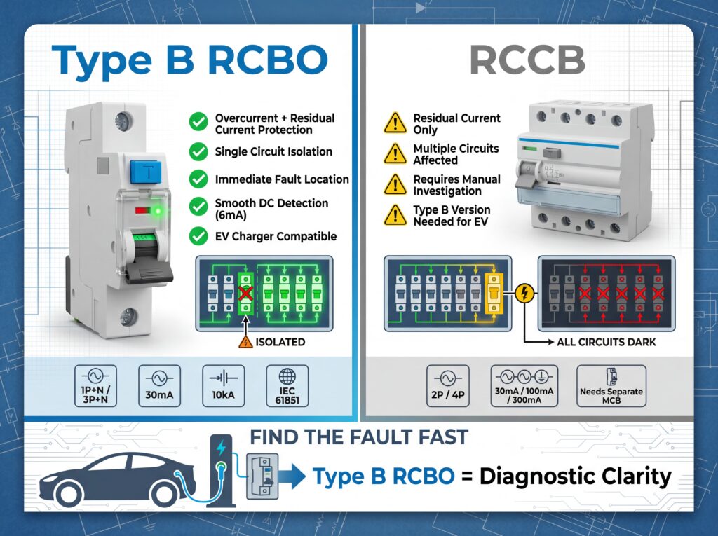
With a dedicated RCBO, the homeowner can see that only the EV charging circuit has disconnected. The electrician can start with the charging cable, EVSE, vehicle connection and final-circuit wiring while the rest of the home remains supplied.
With one RCCB protecting the garage, freezer, sockets and EV charger, the same residual-current fault can disconnect the entire group. The technician must isolate each downstream circuit before locating the source. The problem is the shared architecture, not the fact that the protective device is called an RCCB.
Individual RCBOs provide a trip pattern by charging bay. If Bay 3 repeatedly trips while the other feeders remain stable, testing can concentrate on that EVSE and circuit. The failed bay can remain isolated while other chargers operate.
A central RCCB protecting several charging points gives less information and can stop the whole group. Where a shared arrangement is used, branch leakage monitoring, EVSE event logs and clearly labelled isolation points become more important.
A combined RCBO may have a trip-position or indicator that distinguishes residual-current operation from overcurrent operation, but this feature is product-specific. Read the device documentation. With a separate RCCB and MCB, the operated device often provides an immediate clue: RCCB operation points toward residual current, while MCB operation points toward overload or short circuit. Either arrangement can support diagnosis when it is correctly labelled and documented.
The original article stated that Type B is mandatory for all EV charging applications. That is too broad. For many Mode 3 AC chargers, a Type A or Type F RCD used with a compliant 6 mA RDC-DD can be permitted by the equipment manufacturer and local rules. Type B is appropriate when the possible residual-current waveform requires it, when the EVSE lacks suitable DC detection, or when the manufacturer or regulation specifies it.
A Type B RCBO is also not a “6 mA smooth DC detector.” Type B devices operate according to their declared Type B residual-current characteristics. The 6 mA value is commonly associated with an RDC-DD used to protect an upstream Type A or Type F RCD from the effects of smooth DC.
| Project condition | Usually favours individual RCBOs | May favour RCCB + MCB |
|---|---|---|
| Continuity of service | Each final circuit remains independent | Acceptable when the RCCB protects one dedicated feeder |
| Fast fault localisation | Trip identifies the affected circuit | Separate devices can distinguish leakage from overcurrent |
| Several charging points | Individual protection limits outage | Grouped design can reduce device count but increases outage scope |
| Limited board space | Compact RCBO may help; check actual module width | Separate devices may need more modules |
| Maintenance strategy | One combined replacement unit | Individual RCCB or MCB can be replaced separately |
| Procurement | One device reference per circuit | Separate stocked devices can be flexible |
| Selektivität | Requires coordination with upstream RCDs | Also requires upstream and downstream coordination |
Repeated resetting without testing can expose equipment and users to risk and can erase useful fault evidence. Qualified personnel should follow the applicable isolation and test procedures.
Do not apply a universal “125% continuous-load rule” to every EV charger installation unless the local wiring standard or product instructions require that method. Determine the protective-device rating from the EVSE maximum current, conductor capacity, installation method, ambient temperature, grouping, manufacturer instructions and national rules.
| Artikel | Selection check |
|---|---|
| Nennstrom In | Must protect the cable and support the EVSE’s declared maximum current |
| Trip curve | Use the curve specified or supported by the EVSE manufacturer and fault-loop design |
| Ausschaltvermögen | Must be at least suitable for the prospective short-circuit current at the installation point |
| IΔn | Commonly 30 mA for required additional protection; verify local rules |
| Fehlerstrom-Typ | Type A/F with suitable DC detection or Type B as required |
| Pole | Match phases, neutral arrangement and required isolation |
| Supply system | Confirm TN, TT or IT design and required disconnection times |
It provides integrated overcurrent protection and often clearer circuit-level isolation. A dedicated Type B RCCB plus MCB can provide equivalent protection functions with separate devices. The better choice depends on space, maintenance, cost and coordination.
It may be possible if the design, normal leakage, local rules and EVSE instructions allow it. However, one fault can disconnect all chargers, and cumulative leakage and selectivity must be assessed.
Possibly, when the EVSE includes suitable 6 mA RDC-DD protection and the manufacturer and local regulations allow the arrangement. Type A alone is not a universal answer.
Do not describe it that way unless the manufacturer declares that exact characteristic. Type B operation follows its product standard and declared ratings. A 6 mA threshold is commonly associated with an RDC-DD.
Possible causes include insulation failure, moisture, damaged cable, vehicle fault, excessive normal leakage, wrong RCD type, incorrect neutral wiring, overload, short circuit or poor upstream coordination.
Individual RCBOs often improve continuity and fault localisation. Final requirements depend on the installation design, local rules and acceptable outage scope.
Check the product’s trip indicator and documentation. With separate devices, note whether the RCCB or MCB operated. Then confirm with electrical tests rather than relying only on the handle position.
IEC/EN 61009-1 covers household and similar RCBOs; Type B residual-current characteristics also require the applicable Type B product requirements, commonly IEC/EN 62423. Verify the exact product declaration.
For individual-circuit protection, compare KUANGYA RCBO options. For separate residual-current protection, review the RCCB range. For EVSE-specific selection and project documentation, contact the technical team with the charger model, supply system and required ratings.

