WengYang Industrial Zone Yueqing Wenzhou 325000
Work Hours
Monday to Friday: 7AM - 7PM
Weekend: 10AM - 5PM
WengYang Industrial Zone Yueqing Wenzhou 325000
Work Hours
Monday to Friday: 7AM - 7PM
Weekend: 10AM - 5PM

The world is undergoing an electrical revolution. From the proliferation of solar photovoltaic (PV) installations and battery energy storage systems (BESS) to the rapid growth of electric vehicle (EV) charging infrastructure, Direct Current (DC) power is no longer a niche technology. It is rapidly becoming the backbone of a decentralized, renewable energy future. However, this shift brings a critical engineering challenge that is often underestimated: the safe interruption of DC circuits.
Unlike Alternating Current (AC), which naturally passes through zero volts 100 or 120 times per second (at 50/60Hz), providing a momentary opportunity to extinguish an electrical arc, DC is relentless. When you open a switch in a live DC circuit, the current doesn’t want to stop. It will attempt to jump the air gap, creating a continuous, high-temperature plasma arc that can sustain itself until something melts, burns, or fails catastrophically. This makes DC switching fundamentally more dangerous and demanding than its AC counterpart. An AC-rated switch used in a DC application is a fire hazard waiting to happen.
Choosing the right DC switch-disconnector isn’t just about matching voltage and current; it’s about ensuring the device can safely and reliably make and break a connection under both normal and fault conditions. This article provides a comprehensive, five-step guide for engineers, designers, and technicians to select the correct DC switch that ensures system safety, reliability, and compliance with international standards.
Before diving into the selection process, it’s crucial to understand the primary standard governing these devices: IEC 60947-3, “Low-voltage switchgear and controlgear – Part 3: Switches, disconnectors, switch-disconnectors and fuse-combination units.” This standard establishes the performance requirements and testing procedures for the devices used to isolate or switch DC circuits.
One of the most important concepts within IEC 60947-3 is the Utilization Category. This classification system defines the type of electrical load the switch is designed to handle, including the expected stress during making and breaking operations. Using a switch with the wrong utilization category for your application can lead to premature failure or an inability to perform its function safely. For DC circuits, the key categories are detailed in the table below.
Table 1: DC Utilization Categories Explained
| Category | Description | Typical Application | Key Considerations |
|---|---|---|---|
| DC-20 | Connecting and disconnecting circuits under no-load conditions. | Pure isolation tasks where the load is always switched off by another device first. | The device provides a safe air gap (isolation) but has no load-breaking capacity. Also known as an isolator. |
| DC-21A | Switching of resistive loads, including moderate overloads. Intended for infrequent operation. | Switching resistive heating elements or lighting circuits that are not frequently used. | Capable of breaking the full load current but not designed for constant, repetitive use. |
| DC-21B | Switching of resistive loads, including moderate overloads. Intended for frequent operation. | General-purpose load switching in DC control panels and distribution boards. | Built for durability and a higher number of mechanical and electrical operations than DC-21A. |
| DC-PV2 | Switching of photovoltaic circuits that may be under load. | Isolation of PV strings or arrays for maintenance. | Specifically designed to handle the unique characteristics of solar PV circuits, which operate at a near-constant current and can present challenging load-breaking conditions. |
For most modern applications like solar energy and battery storage, specifying a switch rated for DC-21B or DC-PV2is critical to ensure it can handle the operational demands of the system.
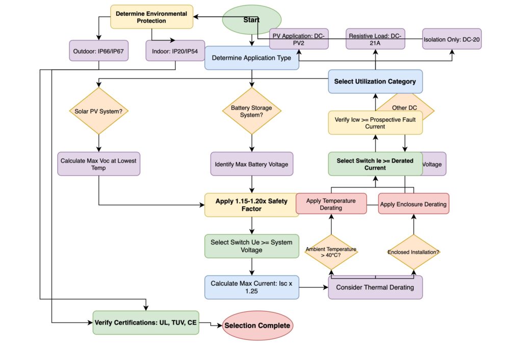
To simplify the process of choosing the correct DC switch, follow this systematic, five-step methodology. This approach ensures all critical parameters are considered, leading to a safe and reliable design.
A visual summary of the systematic 5-step selection process.
The first and most fundamental parameter is the system voltage. The selected switch must have a rated operational voltage (Ue) that is equal to or greater than the maximum voltage it will ever experience.
For battery systems, this is relatively straightforward—it’s the nominal battery voltage plus any charging voltage tolerances. However, for solar PV systems, it’s more complex. The critical value is the open-circuit voltage (Voc) of the PV string, not the operating voltage (Vmp). Furthermore, this Voc must be corrected for temperature.
Photovoltaic panels behave counter-intuitively: their voltage increases as the ambient temperature decreases. A solar array that produces 800Vdc on a warm day might produce over 950Vdc on a freezing winter morning. Failing to account for this “cold-weather effect” can lead to a voltage that exceeds the switch’s rating, creating a serious safety risk. Always use the temperature correction coefficients found in the PV module’s datasheet to calculate the worst-case (lowest temperature) maximum system voltage.
Rule of Thumb: Select a DC switch with a voltage rating at least 15-20% higher than the calculated maximum system voltage to provide a robust safety margin.
The rated operational current (Ie) of the switch must be greater than the continuous operating current of the load. For a PV system, this would be the string’s short-circuit current (Isc) multiplied by a safety factor (typically 1.25 as per NEC requirements).
However, a switch’s nominal current rating is almost never its true capacity in a real-world installation. This is where thermal derating becomes essential. A switch’s ability to carry current is limited by its ability to dissipate heat. Several factors can reduce this ability:
Always consult the manufacturer’s datasheet for specific derating curves and apply them diligently. A 100A switch might only be suitable for a 65A load once all derating factors are applied.
While a switch-disconnector is not a circuit breaker—it is not designed to interrupt a high-level short circuit—it must be able to withstand the electromechanical forces and thermal stress of a fault long enough for the upstream protective device (e.g., a fuse or circuit breaker) to operate. This rating is the rated short-time withstand current (Icw).
The Icw rating is typically given for a specific duration, most commonly one second (e.g., “12kA for 1s”). This means the switch can structurally survive a 12,000-amp fault for one second without rupturing, melting, or welding its contacts shut, ensuring the circuit remains safely contained until the fault is cleared. The Icw rating of your switch must be higher than the prospective short-circuit current at its point of installation in the system. This is a critical safety parameter that protects equipment and personnel from the violent effects of a short-circuit event.
The switch must be suitable for its installation environment. This is primarily defined by its Ingress Protection (IP) rating or, in North America, its NEMA enclosure type rating. The IP rating system uses two digits to classify the level of protection against solids (first digit) and liquids (second digit).
Table 4: Common IP Ratings and Their Applications
| IP Rating | Protection Against Solids | Protection Against Liquids | Typical Application |
|---|---|---|---|
| IP20 | Protected against objects >12.5mm (e.g., fingers). | No protection. | Inside a secure, dry control panel. Not accessible to untrained personnel. |
| IP65 | Dust-tight. | Protected against low-pressure water jets from any direction. | General outdoor use, industrial wash-down areas, dusty environments. |
| IP66 | Dust-tight. | Protected against powerful water jets from any direction. | Rooftop solar installations, marine environments, areas exposed to heavy rain. |
| IP67 | Dust-tight. | Protected against temporary immersion in water (up to 1m for 30 mins). | Locations with a risk of flooding or temporary submersion. |
For outdoor applications, especially in solar, UV resistance is also mandatory. Standard plastics will become brittle and fail when exposed to sunlight over time. Look for switches made from UV-stabilized polycarbonate (PC) or similar durable materials.
Finally, a switch’s datasheet is only a claim until it is verified by a reputable third party. Independent certifications provide confidence that the device has been tested and meets the safety and performance standards it claims to. Key marks to look for include:
Never use non-certified components in a critical power system. The cost savings are negligible compared to the risk of catastrophic failure, fire, and potential liability.
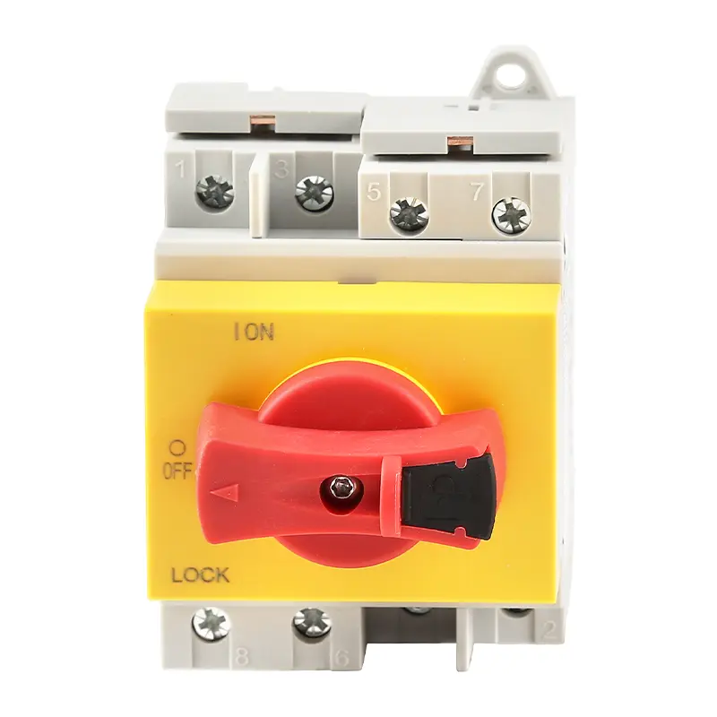
DC switches are available in several physical formats, each suited to different installation needs. The most common are panel-mount, DIN rail, and fully enclosed switches.
Caption: Panel-mount DC switches offer a robust, through-door interface for operators, often featuring lockable handles for safety isolation (LOTO).
Caption: DIN rail mount switches allow for fast, modular installation inside control cabinets and distribution boards.
Table 2: Comparison of Switch Mounting Types
| Mounting Type | Installation Method | Key Advantages | Best Suited For |
|---|---|---|---|
| Panel Mount | Mounted through a hole cut in the door or front plate of an enclosure. | Highly visible, easily accessible operator handle; robust mounting. | Main isolators on control panels, operator stations. |
| DIN Rail Mount | Snapped onto a standard 35mm DIN rail inside an enclosure. | High-density, modular, and fast installation; easy to wire in-panel. | Distribution boards, combiner boxes, control cabinets with multiple circuits. |
| Enclosed | Pre-installed by the manufacturer in a dedicated IP-rated, UV-resistant box. | All-in-one solution, guaranteed environmental protection; simplifies procurement. | Standalone local isolators for outdoor equipment like AC units or PV arrays. |
What truly separates a high-quality DC switch from a substandard one is the science happening inside the box. Two key areas determine a switch’s ability to safely break a DC load: the contact materials and the arc-extinguishing mechanism.
While copper is an excellent conductor, it has a significant drawback: it oxidizes readily. This layer of copper oxide is far less conductive and can lead to hot spots, increased resistance, and eventual failure. Silver is superior because its oxide (silver oxide) remains highly conductive.
For high-performance DC switches, manufacturers use silver alloys. Alloying pure silver with materials like nickel (AgNi) or tin-oxide (AgSnO2) dramatically improves its resistance to material erosion and welding during an arcing event.
Caption: Silver-alloy contacts (AgNi shown) provide superior durability and resistance to arc damage compared to standard copper contacts.
Table 3: Comparison of Contact Materials
| Material | Conductivity | Arc & Oxidation Resistance | Cost | Overall Performance |
|---|---|---|---|---|
| Copper | Excellent | Poor | Low | Unsuitable for reliable DC load-breaking. |
| Silver | Highest | Good | High | Good, but can be soft and prone to mechanical wear. |
| Silver Alloy (AgNi, AgSnO2) | Very Good | Excellent | Very High | The optimal choice for performance and longevity in demanding DC applications. |
When the contacts open, an arc is formed. The switch’s job is to extinguish this arc as quickly as possible. High-quality DC switches employ several mechanisms simultaneously:
A switch that combines these features—especially double-break contacts and magnetic arc chutes—will provide vastly superior DC load-breaking performance and a longer operational life.
1. Can I use an AC switch for a DC application?
Absolutely not. An AC switch relies on the zero-crossing point of the AC waveform to help extinguish the arc. DC current is continuous, so an AC switch will likely fail to break the circuit, leading to a sustained arc, overheating, and a significant fire risk.
2. What is the difference between a “switch” and a “disconnector”?
A disconnector (or isolator) is designed only for opening a circuit under no-load conditions to provide a safe isolation gap for maintenance (Category DC-20). A switch is designed to make and break the circuit under normal load conditions (Category DC-21). A “switch-disconnector” meets the requirements for both functions.
3. Why is derating for temperature so important?
Heat is the primary enemy of electrical components. A switch’s current rating is based on its ability to dissipate the heat generated by that current. Higher ambient temperatures reduce this ability, causing the switch to run hotter for the same load, which can exceed its temperature limits, degrade insulation, and lead to premature failure.
4. What does the “PV2” in DC-PV2 utilization category mean?
DC-PV2 is a specific category within the IEC standard created for the challenges of switching photovoltaic systems. It certifies that the switch is capable of safely interrupting the unique current/voltage characteristics of a PV array under load, which can be more difficult to extinguish than a standard resistive load.
5. What happens if my switch’s voltage rating is too low?
If the system voltage (especially the peak Voc in a cold PV system) exceeds the switch’s rating, the air gap inside may not be sufficient to insulate the voltage. This can cause the arc to fail to extinguish when opening or, in a worst-case scenario, for the current to flashover inside the switch, causing a catastrophic failure.
6. Is a higher IP rating always better?
Not necessarily. Higher IP ratings (like IP67) often mean a more tightly sealed enclosure, which can trap more heat and require greater thermal derating. The best approach is to choose the IP rating that appropriately matches the specific installation environment without over-engineering. An IP65 switch is often sufficient for many outdoor locations.
7. How does altitude affect a DC switch?
At higher altitudes (above 2000m), the air is less dense. This has two effects: 1) Reduced cooling capacity, requiring current derating. 2) Reduced dielectric strength, meaning a higher voltage is more likely to jump a gap, requiring voltage derating.
8. What are “double-break” contacts?
This is a design where a single switching action opens the circuit path in two separate places simultaneously. This divides the arc energy into two smaller, more manageable arcs, making them easier and faster to extinguish and significantly improving the DC breaking capacity of the switch.
Selecting the right DC switch-disconnector is not a trivial task. It is a critical engineering decision that has a direct impact on the safety, reliability, and lifespan of the entire power system. Simply matching the nameplate voltage and current is insufficient and dangerous.
By following the five-step process—evaluating system voltage with temperature correction, applying rigorous thermal derating to the load current, verifying short-circuit withstand, assessing environmental needs, and demanding third-party certification—engineers and designers can move from simple component selection to robust system design. Understanding the internal science of contact materials and arc-quenching mechanisms further empowers you to specify a product that is not just compliant, but genuinely superior.
Ultimately, a methodical approach ensures that the chosen device will perform its most critical function flawlessly: to disconnect power safely and reliably, every single time.
Caption: The goal of the selection process is to find a switch in the “Optimized & Reliable” quadrant, balancing performance, compliance, and cost-effectiveness without compromising safety.
