Address
304 North Cardinal
St. Dorchester Center, MA 02124
Work Hours
Monday to Friday: 7AM - 7PM
Weekend: 10AM - 5PM
Address
304 North Cardinal
St. Dorchester Center, MA 02124
Work Hours
Monday to Friday: 7AM - 7PM
Weekend: 10AM - 5PM

In modern electrical infrastructure, direct current (DC) systems are becoming increasingly prevalent—from solar photovoltaic installations and battery energy storage systems to telecommunications networks and electric vehicle charging stations. However, these DC systems face a critical vulnerability: transient voltage surges caused by lightning strikes, switching operations, and grid disturbances. A single unprotected surge event can destroy sensitive electronics, halt operations, and result in costly downtime. This is where DC surge protection devices (DC SPDs) become essential safeguards for your electrical infrastructure.
This comprehensive guide explores everything you need to know about DC surge protection devices—from their fundamental working principles and various types to real-world applications and selection criteria. Whether you’re designing a solar installation, specifying equipment for a data center, or upgrading industrial control systems, understanding DC SPDs will help you make informed decisions that protect your investment and ensure system reliability.
A DC surge protection device (DC SPD) is a protective component designed to limit transient overvoltages and divert surge currents in direct current electrical systems. Unlike their AC counterparts, DC SPDs are specifically engineered to handle the unique characteristics of DC circuits, including the absence of natural current zero-crossings and the potential for sustained fault currents.
The primary function of a DC SPD is to detect voltage surges that exceed safe operating levels and provide a low-impedance path to ground, effectively shunting the excess energy away from sensitive equipment. These devices operate in microseconds, responding faster than conventional circuit protection devices, thereby preventing damage to connected loads.
DC surge protection devices differ fundamentally from AC surge protectors in several critical aspects. DC systems lack the periodic voltage zero-crossing that occurs in AC systems, which means that once a protective element conducts in a DC circuit, it must actively interrupt the follow-on current rather than waiting for a natural current zero. This requirement demands specialized components and design approaches unique to DC applications.
| Parameter | Typical Range | Description |
|---|---|---|
| Maximum Continuous Operating Voltage (MCOV) | 48V – 1500V DC | Highest voltage the SPD can withstand continuously |
| Voltage Protection Level (Up) | 1.2 – 4.0 kV | Maximum voltage let-through during surge events |
| Nominal Discharge Current (In) | 5 – 40 kA (8/20 µs) | Standard test current for classification |
| Maximum Discharge Current (Imax) | 20 – 100 kA (8/20 µs) | Peak surge current the device can handle |
| Response Time | < 25 ns | Time to activate protection |
| Operating Temperature | -40°C to +85°C | Environmental operating range |
The fundamental function of a DC surge protection device is threefold: detection, diversion, and dissipation of transient overvoltages. When a surge event occurs—whether from a nearby lightning strike, inductive load switching, or electrostatic discharge—the SPD must instantly recognize the threat, create a low-resistance pathway to ground, and safely dissipate the surge energy without allowing damage to propagate to connected equipment.
Why is this protection necessary? DC systems, particularly those involving renewable energy sources, battery banks, and electronic control systems, contain sensitive semiconductor components that operate within narrow voltage tolerances. A voltage spike of just 20-30% above rated levels can cause immediate failure of power electronics, microprocessors, and communication interfaces. In solar installations, for example, inverters containing complex IGBT-based switching circuits are especially vulnerable to surge-induced failures that can cost thousands of dollars to repair and result in significant energy production losses.
DC SPDs solve multiple critical problems simultaneously. They protect against direct lightning strikes by providing a preferential current path with impedance far lower than that of protected equipment. They mitigate induced surges from nearby lightning activity through magnetic and capacitive coupling. They suppress switching transients generated by inductive loads such as motors, contactors, and transformers. Additionally, they guard against surges originating from the utility grid that can couple into DC systems through power conversion equipment.
The economic justification for DC surge protection is compelling. The cost of a properly specified SPD represents typically 1-3% of the total system value, yet it protects against failures that could destroy 30-50% of system components. In mission-critical applications such as telecommunications infrastructure or hospital backup power systems, the indirect costs of downtime—lost revenue, emergency repairs, and reputational damage—far exceed the direct equipment replacement costs.
While both DC and AC surge protection devices serve the fundamental purpose of protecting electrical systems from transient overvoltages, their design, operation, and application differ significantly due to the inherent characteristics of the power systems they protect.
The most critical distinction lies in current interruption capability. AC systems naturally pass through zero voltage and current twice per cycle (100 or 120 times per second at 50/60 Hz), which allows protective elements to extinguish arcs and reset automatically. DC systems maintain constant polarity and voltage, meaning that once a protective element conducts, it must actively suppress the follow-on current. This requirement necessitates the use of specialized components in DC SPDs, such as thermal disconnectors, series impedance elements, or active current-limiting circuits.
Voltage ratings also differ substantially. AC surge protectors are rated based on RMS voltage values, while DC SPDs must account for the continuous DC voltage level without the benefit of periodic zero-crossings. A 230V AC SPD experiences peak voltages of approximately 325V, but a 230V DC system maintains 230V continuously, placing different stress on protective components.
Installation considerations vary as well. AC SPDs typically connect between phase conductors and ground, or between phases in three-phase systems. DC SPDs must be installed with careful attention to polarity, often requiring protection on both positive and negative conductors relative to ground, particularly in systems with floating or bipolar configurations common in solar installations and telecommunications equipment.
The testing standards also reflect these differences. AC SPDs are evaluated according to IEC 61643-11 and UL 1449, while DC SPDs follow IEC 61643-31 and UL 1449 DC supplement, which include specific tests for DC follow-on current interruption capability and continuous DC voltage stress.
Understanding how DC surge protection devices operate requires examining both the components involved and the sequence of events during a surge condition. The working principle can be broken down into distinct phases that occur within microseconds.
Step 1: Normal Operation State
Under normal operating conditions, the DC SPD presents extremely high impedance (typically >1 MΩ) between the protected circuit and ground. This high-impedance state ensures that the SPD does not interfere with normal system operation, draws negligible leakage current (usually <1 mA), and does not affect system efficiency. The SPD continuously monitors the voltage across its terminals, ready to respond instantly to any overvoltage condition.
Step 2: Surge Detection and Activation
When a transient overvoltage occurs—exceeding the SPD’s voltage protection level—the protective elements within the device undergo a rapid transition from high-impedance to low-impedance state. This transition occurs in nanoseconds, typically within 25 ns for modern metal oxide varistor (MOV) based devices. The speed of this response is critical because surge events have extremely fast rise times, often reaching peak values in less than 1 microsecond.
Step 3: Surge Current Diversion
Once activated, the SPD creates a low-impedance path (typically 0.1-1 Ω) to ground, effectively becoming a short circuit for the surge current. This diverts the majority of the surge energy away from the protected equipment. The SPD must be capable of handling the full surge current magnitude, which can range from several kiloamperes for switching transients to over 100 kA for direct lightning strikes in Type 1 applications.
Step 4: Energy Dissipation
As surge current flows through the SPD, the energy is dissipated primarily as heat within the protective elements. High-quality DC SPDs incorporate thermal management features including heat sinks, thermal coupling to mounting rails, and temperature-monitoring circuits. The energy dissipation capability is characterized by the device’s energy rating, typically expressed in kilojoules (kJ), which must exceed the expected surge energy in the application.
Step 5: Voltage Clamping
During the surge event, the SPD maintains a clamped voltage across its terminals—the voltage protection level (Up). This clamped voltage represents the maximum voltage that protected equipment will experience. The lower this value, the better the protection, but it must be sufficiently above the normal operating voltage to prevent nuisance activation. For a 1000V DC system, a typical Up might be 1800-2200V, providing adequate protection margin while maintaining selectivity.
Step 6: Current Interruption and Reset
This step represents the most challenging aspect of DC surge protection. After the surge current subsides, a follow-on current may continue to flow from the DC source through the now-conducting SPD. Unlike AC systems where current naturally crosses zero, DC SPDs must actively interrupt this follow-on current. Different technologies accomplish this through various mechanisms:
Step 7: Return to Normal State
After successfully interrupting any follow-on current, the SPD returns to its high-impedance monitoring state, ready to respond to subsequent surge events. Quality DC SPDs can handle multiple surge events over their lifetime, with proper designs rated for thousands of operations before requiring replacement.

DC surge protection devices are classified into several categories based on their protective technology, application location, and performance characteristics. Understanding these types is essential for selecting the appropriate protection for your specific application.
Spark gap technology represents one of the oldest and most robust forms of surge protection, utilizing a controlled air gap between electrodes that breaks down and conducts when voltage exceeds a specific threshold.
Working Mechanism: The device consists of two or more electrodes separated by a precise air gap or gas-filled chamber. Under normal voltage conditions, the gap acts as an insulator. When surge voltage reaches the breakdown threshold, the air or gas ionizes, creating a conductive plasma channel that carries the surge current to ground. Advanced designs incorporate multiple gaps in series to achieve precise voltage triggering levels and improve current interruption capability.
Advantages: Spark gap SPDs offer exceptional surge current handling capability, often rated for 100 kA or higher, making them ideal for direct lightning protection. They exhibit virtually zero leakage current during normal operation and can withstand repeated surge events without degradation. Their fail-safe mode typically results in an open circuit, preventing system shutdown. The technology is highly reliable with operational lifespans exceeding 25 years in properly designed installations.
Suitable Applications: These devices are primarily deployed as Type 1 (Class I) protection at service entrance points where direct lightning strikes are possible, such as solar array junction boxes, wind turbine nacelles, and telecommunications tower equipment. They are essential in exposed installations including rooftop solar systems, remote monitoring stations, and outdoor electric vehicle charging infrastructure.
Metal oxide varistor technology dominates the surge protection market due to its excellent balance of performance, cost, and reliability. MOVs consist of zinc oxide ceramic material with nonlinear voltage-current characteristics.
Working Mechanism: The MOV contains microscopic zinc oxide grains separated by grain boundaries that act as semiconductor junctions. At normal operating voltages, these junctions present high resistance. When surge voltage is applied, the junctions break down simultaneously, creating multiple parallel conduction paths through the material. This results in a highly nonlinear response where resistance drops dramatically as voltage increases, effectively clamping the voltage while conducting large currents.
Advantages: MOV-based SPDs provide fast response times (typically <25 ns), excellent clamping characteristics with low voltage protection levels, and high energy absorption capacity. They handle repetitive surges well and offer good cost-performance ratios. Modern MOV designs incorporate thermal disconnectors and fault indicators for enhanced safety and maintenance visibility.
Suitable Applications: MOV-based DC SPDs are widely used in solar photovoltaic systems for both string and inverter protection, battery energy storage systems, DC distribution panels in data centers, electric vehicle charging stations, and industrial DC motor drives. They serve effectively as Type 2 (Class II) protection at equipment distribution points and as Type 3 protection at individual equipment terminals.
Silicon avalanche diode technology provides precision voltage clamping for sensitive electronic equipment requiring tight voltage tolerances.
Working Mechanism: SAD devices utilize specially designed PN junctions that operate in reverse breakdown mode. When reverse voltage exceeds the avalanche breakdown voltage, the depletion region experiences impact ionization, creating electron-hole pairs that conduct current. This process occurs extremely rapidly and provides precise, repeatable voltage clamping. Multiple diodes are often configured in series to achieve desired voltage ratings.
Advantages: These devices offer the fastest response times available (<1 ns), extremely precise voltage clamping with minimal tolerance variation, and bidirectional protection capability. They generate minimal capacitance, making them suitable for high-frequency signal protection. SAD-based SPDs maintain consistent performance across wide temperature ranges and exhibit excellent aging characteristics.
Suitable Applications: SAD technology is preferred for protecting sensitive electronics including communication interfaces (RS-485, CAN bus), measurement and control circuits, data acquisition systems, and power electronics control boards. They are essential in applications where voltage tolerance is critical, such as medical equipment, precision instrumentation, and aerospace systems.
Hybrid surge protection devices combine multiple protective technologies in a coordinated configuration to achieve superior performance characteristics that exceed what any single technology can provide.
Working Mechanism: A typical hybrid design integrates a spark gap or gas discharge tube as the primary stage for handling high-energy surges, followed by an MOV or SAD secondary stage for precise voltage clamping. The stages are coordinated through impedance elements (inductors or resistors) that ensure proper energy sharing. When a surge occurs, the primary stage handles the bulk of the surge energy, while the secondary stage provides tight voltage clamping to protect sensitive equipment. Some advanced designs incorporate a third stage with ultrafast semiconductor devices for sub-nanosecond response.
Advantages: Hybrid SPDs deliver the best overall protection by combining high surge current capability (from spark gaps), excellent voltage clamping (from MOVs or SADs), and fast response times. They provide superior protection across a wide range of surge magnitudes and waveshapes. The multi-stage design offers redundancy and extended operational life, as each stage can be optimized for its specific function.
Suitable Applications: These premium devices are deployed in critical infrastructure including hospital electrical systems, financial data centers, telecommunications central offices, and industrial control systems where equipment value and downtime costs justify the higher investment. They are particularly valuable in applications requiring both lightning protection and precision voltage regulation, such as solar inverters with integrated communication systems and electric vehicle fast-charging stations with complex power electronics.
DC surge protection devices serve critical roles across diverse industries and applications. Understanding these use cases helps in proper specification and installation planning.
Solar installations represent the largest and fastest-growing application for DC surge protection devices. Photovoltaic arrays are inherently vulnerable to lightning strikes due to their elevated mounting positions, large surface areas, and exposure to weather. A typical solar installation requires multi-level protection.
At the array level, DC SPDs protect junction boxes where multiple strings combine, guarding against direct and induced lightning strikes. String-level protection prevents surges from propagating between parallel strings and protects blocking diodes and monitoring equipment. At the inverter DC input, SPDs provide the final protection stage before power conversion equipment, which contains sensitive IGBT and MOSFET devices that are extremely vulnerable to overvoltage damage.
The technical requirements for solar SPDs include voltage ratings matching the maximum system voltage (typically 600V, 1000V, or 1500V DC), surge current ratings appropriate for the exposure level (20-40 kA for rooftop installations, 40-100 kA for ground-mounted arrays in high-lightning regions), and environmental ratings suitable for outdoor installation (IP65 or higher, -40°C to +85°C operating range). Compliance with IEC 61643-31 and UL 1449 standards is essential for insurance and warranty requirements.
Battery energy storage systems (BESS) require comprehensive surge protection to safeguard both the battery banks and the associated power conversion and management electronics. Lithium-ion batteries, in particular, are sensitive to voltage irregularities that can trigger protection circuits or, in extreme cases, cause thermal runaway.
DC SPDs in BESS applications protect the battery terminals from surges originating from the grid-tied inverter, prevent voltage transients during switching operations, and guard against lightning-induced surges in outdoor installations. The protection strategy must account for the bidirectional power flow characteristic of storage systems, requiring SPDs rated for both charging and discharging modes.
Critical specifications include voltage ratings matching the battery bank configuration (commonly 48V, 400V, or 800V DC), fast response times to protect sensitive battery management systems (BMS), and coordination with existing battery protection circuits to ensure proper selectivity. Temperature monitoring is particularly important in BESS applications, as battery enclosures can experience elevated ambient temperatures that affect SPD performance.
EV charging stations operate at various DC voltage levels (200-1000V DC) depending on charging speed, with fast-charging stations presenting particular protection challenges due to high power levels and complex power electronics.
DC SPDs in charging applications protect the AC-DC converter modules, communication interfaces between the charger and vehicle, and payment and user interface systems. The protection must address surges from both the grid connection and potential transients generated during the connection and disconnection of vehicles.
Specifications must account for the high continuous current levels in fast chargers (up to 500A), voltage ratings appropriate for the charging standard (CHAdeMO, CCS, or GB/T), and protection of communication lines carrying critical safety and billing data. Outdoor charging stations require SPDs with enhanced environmental protection (IP66/67) and extended temperature ranges to ensure reliable operation in all weather conditions.
Telecommunications systems extensively utilize DC power distribution, typically at 48V DC for equipment racks and -48V DC for central office installations. These systems demand extremely high reliability, as downtime directly impacts service availability and revenue.
DC SPDs protect power distribution to radio base stations, fiber optic transmission equipment, switching systems, and backup battery plants. The protection strategy must address both power line surges and surges coupled through cable shields and grounding systems. In tower-mounted equipment, lightning protection is paramount, requiring coordinated SPD installations at multiple points along the power distribution path.
Technical requirements include low voltage protection levels to safeguard sensitive electronics (typically Up < 100V for 48V systems), minimal insertion loss to avoid voltage drop issues in long cable runs, and compatibility with network management systems for remote monitoring. Telecommunications SPDs must meet stringent reliability standards, often requiring NEBS (Network Equipment Building System) certification for carrier-grade installations.
Industrial facilities increasingly employ DC power distribution for programmable logic controllers (PLCs), distributed control systems (DCS), variable frequency drives (VFDs), and sensor networks. These systems are vulnerable to surges generated by motor switching, welding equipment, and lightning strikes to facility infrastructure.
DC SPDs protect control power supplies (typically 24V DC), I/O modules, communication buses (Profibus, Modbus, DeviceNet), and motor drive DC buses. The protection must be coordinated with existing circuit protection to ensure proper selectivity and avoid nuisance tripping during normal industrial operations.
Key specifications include voltage ratings matching industrial standards (12V, 24V, 48V, or higher voltage DC drives up to 1000V), immunity to electrical noise common in industrial environments, and DIN rail mounting for easy integration into control panels. Industrial SPDs should comply with IEC 61643-31 and carry appropriate hazardous location certifications (ATEX, IECEx) when required.
Modern data centers increasingly adopt DC power distribution architectures to improve efficiency and reduce conversion losses. These systems typically operate at 380V DC or 400V DC, distributing power directly to server racks and eliminating individual AC-DC power supplies.
DC SPDs in data centers protect the primary DC distribution bus, zone distribution panels, and rack-level power distribution units. The protection strategy must account for the high availability requirements of mission-critical facilities, often implementing redundant SPD installations with automatic failover capability.
Critical specifications include high continuous current ratings (up to 1000A on main distribution), low voltage protection levels to protect sensitive server electronics, minimal leakage current to avoid ground fault detection issues, and integration with building management systems for real-time monitoring and predictive maintenance. Data center SPDs must demonstrate high reliability with MTBF (mean time between failures) exceeding 1 million hours.
Selecting the appropriate DC surge protection device requires understanding key technical specifications and how they relate to your application requirements. The following parameters are critical for proper specification.
| Specification | Symbol | Description | Selection Criteria |
|---|---|---|---|
| Maximum Continuous Operating Voltage | MCOV (Uc) | Highest DC voltage the SPD can withstand continuously | Must be ≥ 1.2 × maximum system voltage |
| Voltage Protection Level | Up | Maximum voltage let-through during surge | Should be < 80% of equipment withstand voltage |
| Nominal Discharge Current | In | Standard test current (8/20 µs waveform) | Minimum 5 kA for Type 3, 20 kA for Type 2, 40 kA for Type 1 |
| Maximum Discharge Current | Imax | Peak surge current capability | Based on exposure level and risk assessment |
| Short Circuit Current Rating | SCCR | Maximum fault current the SPD can safely interrupt | Must exceed available fault current at installation point |
| Response Time | ta | Time from surge initiation to full conduction | < 100 ns for sensitive electronics, < 25 ns preferred |
| Follow Current Interruption | If | DC follow-on current the SPD can interrupt | Critical for DC applications; verify test certification |
| Operating Temperature Range | – | Environmental temperature limits | Match installation environment; -40°C to +85°C typical |
| Ingress Protection Rating | IP Rating | Protection against dust and moisture | IP20 for indoor, IP65+ for outdoor installations |
DC surge protection devices are classified according to international standards that define their application location and performance requirements:
Type 1 (Class I): Installed at the service entrance or origin of the installation. Must withstand direct lightning current with 10/350 µs waveform. Typical ratings: Iimp = 25 kA to 100 kA per pole.
Type 2 (Class II): Installed at distribution boards and sub-distribution points. Tested with 8/20 µs waveform. Typical ratings: In = 20 kA to 40 kA, Imax = 40 kA to 80 kA.
Type 3 (Class III): Installed at equipment terminals for fine protection. Lower energy ratings but faster response. Typical ratings: In = 5 kA to 10 kA.
Quality DC surge protection devices should carry certifications demonstrating compliance with recognized international standards:
Additional certifications may be required for specific applications, including CE marking for European markets, TÜV certification for solar applications, and NEBS certification for telecommunications equipment.
When specifying a DC SPD, follow this systematic approach:
The cost of DC surge protection devices varies significantly based on technology, performance specifications, and application requirements. Understanding price ranges and cost factors enables informed purchasing decisions that balance protection needs with budget constraints.
Entry-level DC SPDs for basic applications (Type 3, low voltage, indoor use) typically range from $30 to $150 per device. These units provide fundamental protection for 12-48V DC systems with nominal discharge currents of 5-10 kA, suitable for small-scale installations and non-critical applications.
Mid-range DC SPDs for commercial and industrial applications (Type 2, 600-1000V DC, 20-40 kA ratings) generally cost between $150 and $600 per device. This category includes most solar photovoltaic protection devices, battery system SPDs, and industrial control system protectors. These units offer good performance-to-cost ratios for standard installations.
High-performance DC SPDs for critical infrastructure (Type 1, high voltage, 40-100 kA ratings, hybrid technology) range from $600 to $2,500 or more per device. Premium units incorporate advanced features including remote monitoring, predictive maintenance capabilities, and superior surge handling characteristics essential for mission-critical applications.
Technology and components: Hybrid designs combining multiple protective technologies command premium prices due to superior performance and component costs. Single-technology devices (MOV-only or spark gap-only) offer more economical options for applications with less demanding requirements.
Voltage and current ratings: Higher voltage ratings (1000V, 1500V DC) and greater surge current capabilities (Imax > 80 kA) significantly increase costs due to larger protective elements and more robust construction. Each doubling of surge current rating typically adds 40-60% to device cost.
Certification and testing: Devices certified to multiple international standards (IEC, UL, EN) carry higher prices reflecting the testing and compliance costs. Application-specific certifications (NEBS for telecom, ATEX for hazardous locations) add 20-40% to base pricing.
Features and monitoring: SPDs with remote monitoring capabilities, integrated disconnectors, visual and electrical fault indication, and temperature monitoring cost 30-50% more than basic devices but provide significant value through reduced maintenance costs and improved system reliability.
Brand and warranty: Established manufacturers with proven track records typically price products 15-30% higher than lesser-known brands but offer superior technical support, longer warranties (often 5-10 years versus 1-2 years), and better availability of replacement parts.
When purchasing DC surge protection devices, consider total cost of ownership rather than initial purchase price alone. A properly specified SPD costing $500 that prevents a $50,000 equipment failure represents exceptional value, while a $100 inadequate device that fails to protect creates false economy.
Implement a coordinated protection strategy using appropriately rated SPDs at multiple levels rather than relying on a single high-performance device. This approach, known as cascade coordination, provides superior overall protection at lower total cost than attempting to achieve complete protection with a single device.
Purchase SPDs from manufacturers who provide comprehensive technical documentation, including let-through voltage curves, energy ratings, and coordination guidelines. This information is essential for proper system design and ensures compatibility with existing protection schemes.
Consider lifecycle costs including installation labor, maintenance requirements, and replacement intervals. Devices with tool-free mounting, clear status indication, and plug-in replacement modules reduce long-term ownership costs despite potentially higher initial prices.
For large installations, request application engineering support from manufacturers to optimize protection design and ensure proper device selection. Many reputable suppliers provide this service at no charge for significant projects, adding substantial value beyond the product itself.
This is a critical distinction because using the wrong type can lead to safety hazards or inadequate protection.
How to choose:
If your PV array is in an open field with a lightning rod, you need a Type 1 SPD at the main array combiner.
If you are installing a standard rooftop system without an external lightning rod, a Type 2 SPD is usually sufficient. Always check the local electrical code (NEC 690.41 in the US) for mandatory requirements.
Yes, that SPD is likely suitable, and in fact, the voltage margin is good practice. This relates to the concept of “temporary overvoltages” (TOV) .
DC surge protection devices represent essential components in modern electrical infrastructure, providing critical protection for increasingly prevalent DC systems across solar energy, battery storage, electric vehicle charging, telecommunications, and industrial automation applications. The investment in properly specified and installed DC SPDs delivers exceptional value by preventing catastrophic equipment failures, ensuring system reliability, and minimizing costly downtime.
Selecting the appropriate DC surge protection requires careful consideration of system voltage, exposure level, equipment vulnerability, and application-specific requirements. By understanding the working principles, technology options, and performance specifications detailed in this guide, engineers and procurement professionals can make informed decisions that optimize protection while managing costs effectively.
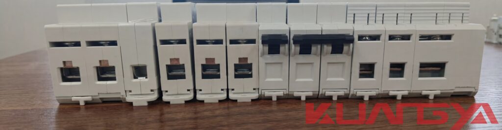
When it comes to buying DC surge protection devices, it is important to buy from a reputable supplier that offers high-quality products at competitive prices. cnkuangya specializes in manufacturing premium DC surge protection devices engineered for demanding applications across renewable energy, industrial, and telecommunications sectors. Our products combine advanced protection technology with rigorous quality control and comprehensive certifications to ensure reliable performance in the most challenging environments.
Explore our complete range of DC surge protection devices designed to meet international standards and protect your critical electrical infrastructure. Contact our technical team for application-specific recommendations and engineering support to ensure optimal protection for your DC systems.
Related Articles:
